

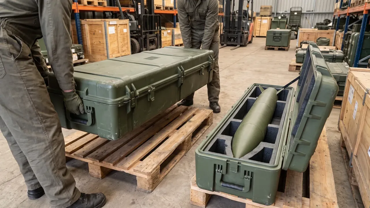
Quick answer: A master photography pre-cut foam hard box is set by tolerances, not foam thickness: a 3 mm kerf, depth within ±1.5 mm and 2 mm of clearance.
Table of contents
- Why tolerances decide a master photography pre-cut foam hard box
- How kerf, slot depth and clearance lock each other
- Wall collapse depends on density and compression
- Layout and centre of gravity across fourteen slots
- What the shell must give the insert
- FAQ
1. Why tolerances decide a master photography pre-cut foam hard box
A master photography pre-cut foam hard box rarely fails on foam thickness. It fails when three tolerances are handled separately: a 3 mm kerf that eats into every slot wall, a ±1.5 mm depth that decides whether floor and lid press together, and 2 mm of clearance that decides whether a finger reaches the edge.
The shell is 560×430×230 mm outside and 505×375×185 mm inside behind a 3.5 mm wall, leaving 27.5 mm per side in plan. Empty 5.4 kg plus an 11 kg load puts 16.4 kg on a 505×375 mm floor at under 1 kPa average pressure.
Depth is the hardest to hold: a blade entering from above wanders as it descends, so ±1.5 mm at 120 mm is the limit of vertical cutting, and ±0.5 mm needs stacked layers.
2. How kerf, slot depth and clearance lock each other
In a master photography pre-cut foam hard box the 3 mm kerf shows only in the finished part. A wall drawn at 9 mm between two slots usually measures 6 mm once cut, and where two kerfs land on the same wall only 3 mm of solid foam is left, which bends under an 11 kg load.
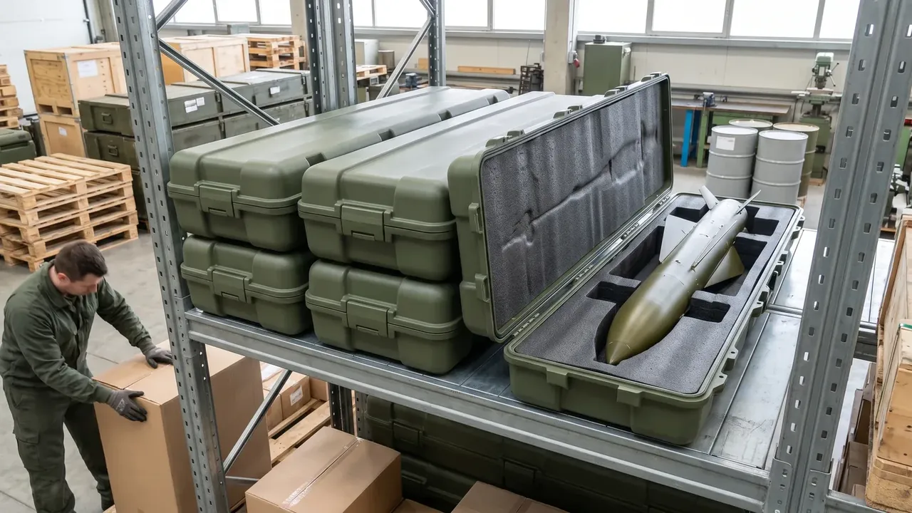
Depth and clearance pull in opposite directions. Open the clearance to 3 mm and the load gains 3 mm of free travel that a 1.2 m drop spends as impact; close it to 1 mm and fingers no longer fit. At 2 mm, thumb and forefinger still pinch an edge and the lateral movement stays inside what the foam wall absorbs.
| Cutting method | Where it is used | Kerf and consequence |
|---|---|---|
| Vertical straight blade | Square slot sides, vertical walls | 3 mm kerf, R3 at corners, sharp corners tear |
| Angled entry | Slots deeper than 90 mm | 45° entry holds depth within ±1.5 mm |
| Stacked layers | Stepped slots with two sections | 30 mm per layer, ≤1 mm offset, 0.3 mm adhesive |
3. Wall collapse depends on density and compression
The walls of a master photography pre-cut foam hard box are held up by density: at 38 kg/m³ a wall resists 0.02 MPa of side pressure without bowing. At 30 kg/m³ a deep wall sags about 2 mm under 11 kg; at 50 kg/m³ peak acceleration in a 1.2 m drop climbs.
Compression is designed at 8%: the insert is cut 0.5 mm oversize per side and the lid presses the top face about 8 mm. Below 5% the insert shifts as a block; above 12% closing force climbs and the two 400 N latches sit under preload.
| Tolerance | Control point | How it is measured |
|---|---|---|
| ±1.5 mm | 120 mm slot depth | Depth gauge at three points, max minus min |
| 3 mm | Kerf width | 3 mm feeler passes, 3.5 mm feeler does not |
| 2 mm | Clearance per side | Six stacked 0.3 mm cards as a plug gauge |
| 0.5 mm | Insert against cavity | A4 sheet clamped at closing, must not pull out |
4. Layout and centre of gravity across fourteen slots
14 slots in a master photography pre-cut foam hard box are grouped by projected area. Three deep slots run lengthwise and take 42% of the floor length, six medium squares fill the middle, four shallow cells sit at the corners and one round bore sits on the edge nearest the handle, about 13,500 mm² per slot.
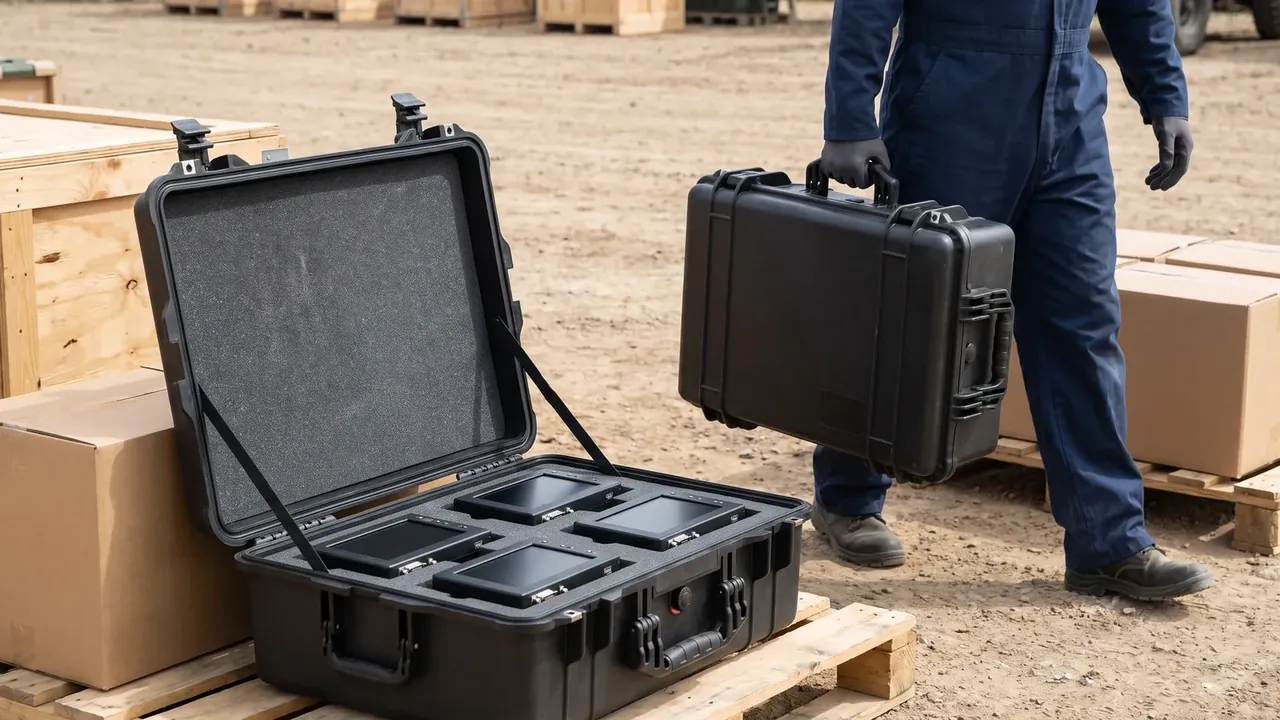
What the layout protects is the centre of gravity. With 11 kg loaded, the centre must fall inside the middle third of the 505 mm length, within 168 mm of either end. Outside that band the case nods when carried by one hand, the load difference between latches passes 30%, and the loaded latch loosens first.
| Slot type | Count | Geometry and value |
|---|---|---|
| Deep lengthwise | 3 | 240×90×120 mm, 25 mm of foam under the floor |
| Medium square | 6 | 110×110×85 mm, R3 corners |
| Shallow cell | 4 | 80×80×45 mm, 1 mm chamfer at the mouth |
| Round bore | 1 | φ70 mm, 95 mm deep, φ8 mm vent at the base |
5. What the shell must give the insert
The 3.5 mm wall is the precondition for a master photography pre-cut foam hard box that fits. A moulded wall shrinks 0.3 mm to 0.5 mm after demoulding, so an insert cut to nominal size sits loose while one cut to the measured cavity jams once temperature moves; 0.5 mm of interference lets the foam absorb it.
Drop and sealing are separate lines, and a master photography pre-cut foam hard box has to clear both. Six faces dropped once from 1.2 m with no latch of the two 400 N units releasing and no slot shifting beyond 2 mm, then IP67 at 1 m for 30 min with no water trace inside; a latch that survives impact says nothing about the gasket.
Temperature and stacking decide long-term set: from −20 ℃ to 60 ℃, soaked 4 h each end, release force must stay within 30%; stacked 3 high, the bottom lid carries about 32.8 kg with residual deformation under 1.5 mm after 24 h.
Conclusion
A master photography pre-cut foam hard box stands on tolerances, not on the foam between shell and load. The 3 mm kerf decides how much solid wall survives, the ±1.5 mm depth decides whether clamping happens at all, and the 2 mm clearance divides the space between fingers and impact travel. With 38 kg/m³ density and a fourteen-slot layout balanced within 168 mm of centre, the shell side closes.
Related Reading
- What pre-cut foam inserts are and where they fall short
- Die-cut insert tooling and layout selection
- Vibration and dust protection in photography cases
- Is foam shedding a cutting problem or a material one
Related Products
- 8 Series — Gun Cases; Military Equipment Cases; Camera Equipment Cases; Drone Cases; Watch Cases; Knife Cases; First Aid Cases; Electronics Equipment Cases
- WL8-2812 PP Gun Case — model WL8-2812
- All protective cases and toolboxes: 7 series, 158 models