

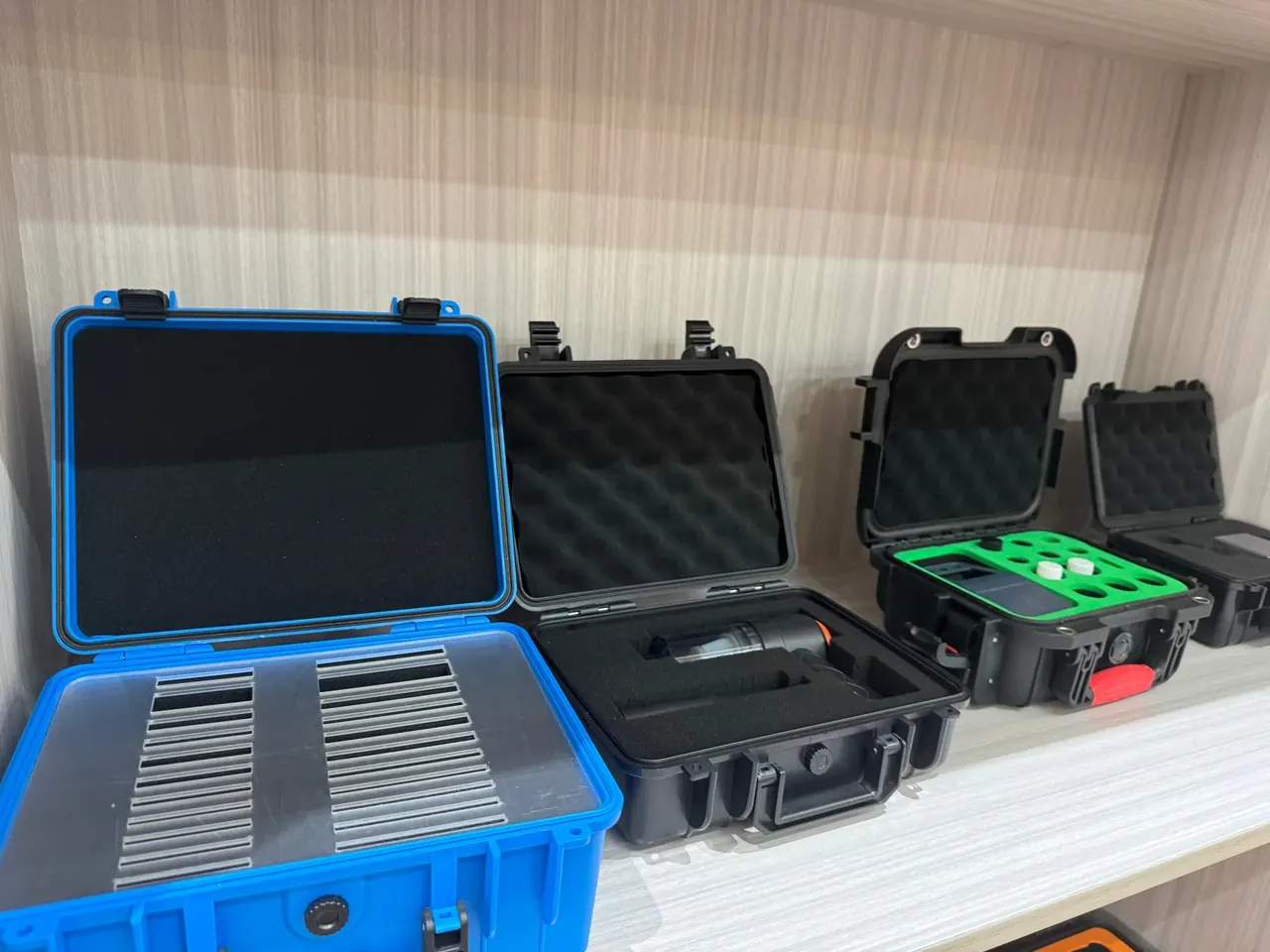
Quick answer: The Medical Sensor Equipment Case uses 24 cells of 42×32×25 mm behind 2.0 mm ribs to hold mis-picks under 0.5%, with 6 colours and 24 position numbers.
Table of contents
- Compartment Granularity in the Medical Sensor Equipment Case
- How the Compartment Array Is Laid Out
- Demoulding Thin Ribs Without Distortion
- Colour Codes and Position Numbers
- Mis-Pick Checks and Records
- FAQ
1. Compartment Granularity in the Medical Sensor Equipment Case
Split the same shell into twenty-four pockets instead of six, and the odds of a wrong pick fall by an order of magnitude. Sensor parts look alike, so two probes two millimetres apart in diameter end up in one large pocket and a finger takes whichever comes first. One part per pocket turns the pick into a straight downward reach, and judgement gives way to geometry.
Granularity is set by part count first and by the hand second. A thumb-and-forefinger pinch needs roughly 25 mm of lateral room; below that the operator reaches for tweezers and the rhythm breaks. The Medical Sensor Equipment Case uses a 42×32×25 mm cell, pinch clearance on the long side, a snug fit on the short side, and 25 mm of depth so a seated part does not rattle.
Twenty-four pockets do not make the case heavy. At 3.6 kg, with 3.5 mm walls, a 345×265×120 mm cavity and a 380×300×150 mm envelope, it lifts in one hand and takes a six-high stack without the bottom unit buckling.
2. How the Compartment Array Is Laid Out
Layout for the Medical Sensor Equipment Case starts with row and column count. Twenty-four cells resolve into 4 rows by 6 columns, spacing taken from cell size plus rib thickness, and with 2.0 mm ribs both ways the cavity length lands exactly on six cells and five ribs. An 8 mm buffer runs around the perimeter.
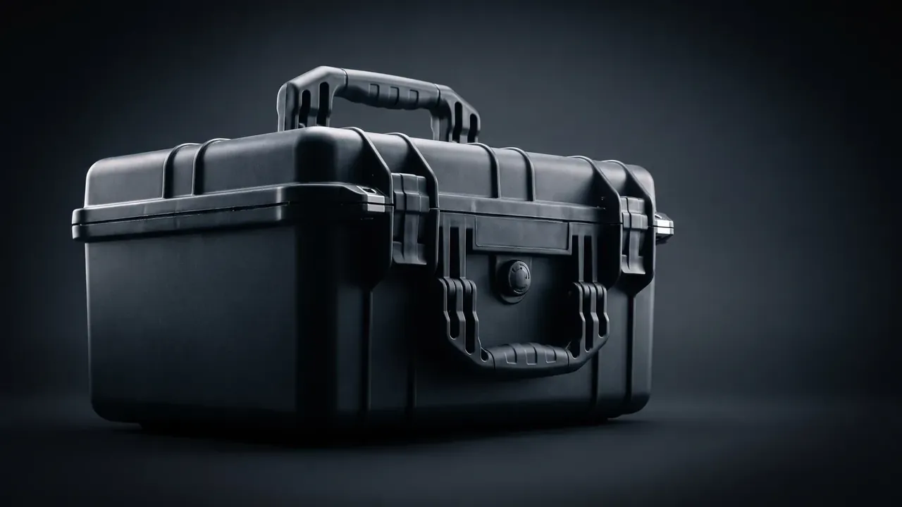
Four by six follows the reach of an arm. With the case flat on a bench the hand sweeps wider than front to back, so six columns scan more naturally; a 3×8 grid narrows the cell.
| Compartment array | Cell size | Picking behaviour |
|---|---|---|
| 2×3, six cells | Large, several parts | Two parts share a cell, sorted by eye |
| 3×4, twelve cells | Medium, snug fit | Head down to confirm the number |
| 4×6, twenty-four cells | 42×32×25 mm | One part per cell, fingertip lands |
| 6×8, forty-eight cells | Small, tweezers needed | Rhythm slows at every pick |
3. Demoulding Thin Ribs Without Distortion
The rib is the thinnest feature in the Medical Sensor Equipment Case, and a 2.0 mm wall cools fastest and meets the ejector first. Practice keeps rib thickness at 0.5 to 0.6 times the main wall and rib draft at 1.5° or more; only when both hold does the rib come out clean.
The mechanism is plain. At ejection the moulding grips the core, tensile stress at the rib root passes yield, and the polymer chains straighten and whiten. Less draft means more grip, and more grip means a clearer mark.
When the 24-cell array carries ribs thinned to 2.0 mm, a draft below 1.5° pulls the ribs white.
| Rib draft | Ejection result | Action |
|---|---|---|
| 0.5° | White root, local sticking | Rework the tool |
| 1.0° | Occasional marks, hand trimming | Open up to 1.5° |
| 1.5° | Clean release, sound root | Release |
| 2.0° | Clean, cell mouth flares slightly | Acceptable on deep cells |
Past 2.0° the cell mouth flares and a burr forms after enough cycles. The 1.5° figure trades clean release against cell-mouth dimension.
4. Colour Codes and Position Numbers
Colour divides the field; numbering locates the cell. Neither replaces the other. Six colours map onto the 4×6 array one per row, so the operator locks the row by colour and the cell by number before the hand moves.
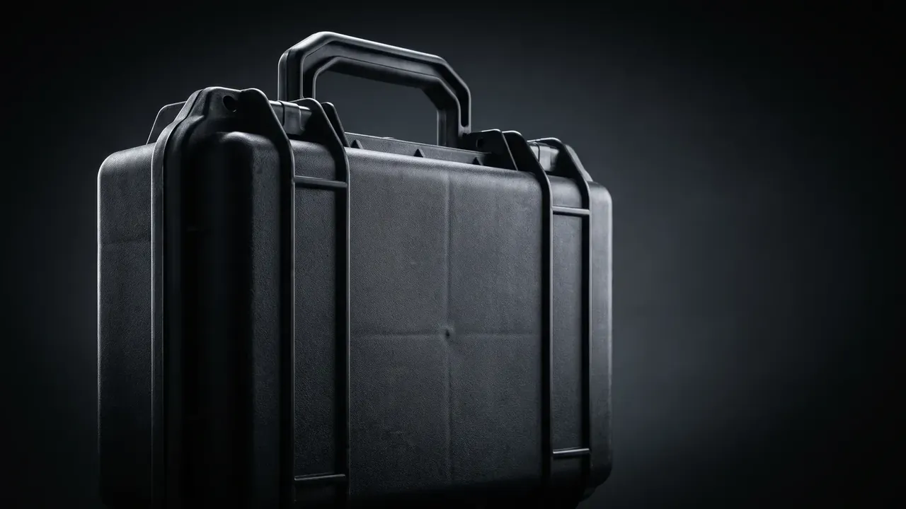
Numbers sit on the cell rim rather than the floor, because the floor is covered by the part and cannot be read at pick time. The 24 positions run row-major, 01 to 06 on the first row, 07 onward on the second, ending at 24, and with colour they form a readable coordinate system.
Colour is moulded in as masterbatch, not applied as a label. A label lifts at the edge and the lifted corner covers the number, which is why the Medical Sensor Equipment Case moulds colour into the thin wall.
5. Mis-Pick Checks and Records
The 0.5% figure for the Medical Sensor Equipment Case is not theoretical; it is the pick plus the check that follows. Numbering alone leaves manual picking at 1% to 2%; one check brings it under 0.5%; a second returns less than it costs.
| Mis-pick check | Action | Result |
|---|---|---|
| No check | Read the number, take the part | 1% to 2% mis-picks |
| Single check | Verify the number after the pick | Under 0.5% |
| Double check | Verify on pick and on return | Around 0.2% |
| Colour plus double | Colour first, then the number | Close to 0.1% |
Two checks is where this structure settles. The first verifies the number as the part leaves, the second verifies number and colour as it goes back, and a working action sits between them, so memory has refreshed and the same wrong call rarely runs twice.
Records stay simple: a shift sheet in three columns, which cell was opened, how often, and whether it went back out of position. The Medical Sensor Equipment Case keeps that sheet inside the lid, visible the moment the case shuts.
Conclusion
Capacity in the Medical Sensor Equipment Case comes down to four numbers: 24 cells, 42×32×25 mm each, 2.0 mm ribs, 1.5° rib draft. Hold those, add 6 colours, 24 numbers and two checks, and mis-picks stay under 0.5%. At 3.6 kg with 3.5 mm walls, two latches at 220 N, an IP65 seam, a six-high stack and a −10 °C to +60 °C transit range, the order inside the cells does not drift.
Related Reading
- The Usable-Volume Calculation
- Hard Case and Carton in Transit
- Tray Compartments for High-Precision Sensors
Related Products
- 8 Series — Gun Cases; Military Equipment Cases; Camera Equipment Cases; Drone Cases; Watch Cases; Knife Cases; First Aid Cases; Electronics Equipment Cases
- WL8-2812 PP Gun Case — model WL8-2812
- All protective cases and toolboxes: 7 series, 158 models