


Quick answer: High precision sensor tray protective box stacks three EVA trays to ±0.3 mm hole tolerance, held by four φ6 mm dowels inside a 395×285×160 mm cavity.
Table of contents
- Tray Stacking in a High Precision Sensor Tray Protective Box
- Hole Tolerance in the EVA Trays
- Dowel Pins and Accumulated Error
- Finger Notches for Lifting a Tray
- What the Sensor Cell Fixes as Standard
- FAQ
1. Tray Stacking in a High Precision Sensor Tray Protective Box
One tray holds too few sensors to justify the lid. Three fill a 395×285×160 mm cavity in a 440×330×200 mm body of 4.1 mm wall, and the stack rides as one block because each tray presses on the one below.
Each tray stands 45 mm, so three come to 135 mm and the lid liner keeps 25 mm to press the top, leaving 2 mm interference at closure. The bottom tray runs 6 mm thick, the upper two 4 mm, and load passes down the rim.
Nothing is glued. A bonded stack is scrapped whole when one pocket fails, while a loose one allows a single tray to be replaced, at the cost of locating each layer by pin.
The High precision sensor tray protective box uses EVA sheet, not thermoformed sheet: thermoformed walls do not give, so a sensor lands on hard plastic, while EVA keeps about 10% compression in reserve after a rough road.
Twenty sensors sit in each tray, sixty in the stack, roughly 6 kg. Lifting happens at the long-side notches; 6 mm corner clearance lets damp air move.
2. Hole Tolerance in the EVA Trays
In this High precision sensor tray protective box, EVA at 45 kg/m³ is the usual grade, around Shore C 45 and 71 kPa at 25% compression. A softer grade lets the wall rock the sensor; a harder one stiffens the mouth until insertion becomes a fight.
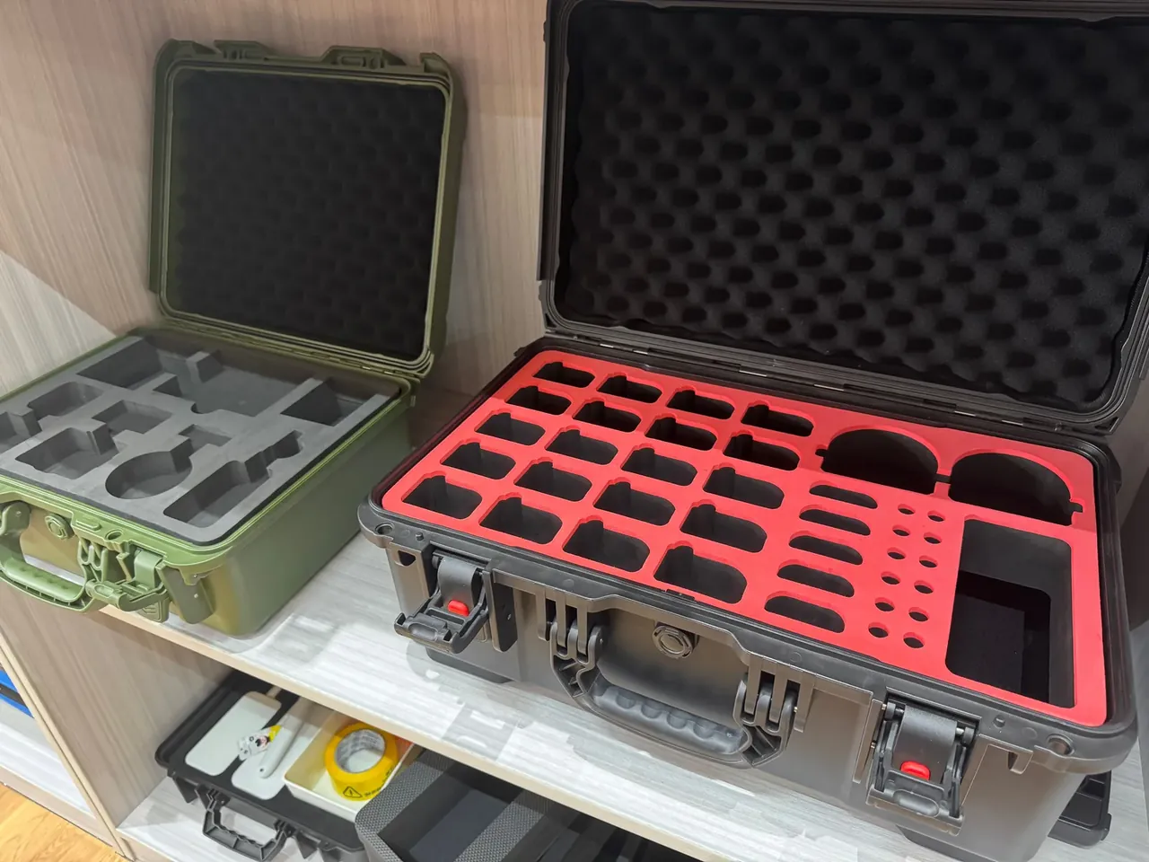
The ±0.3 mm hole tolerance comes from the process, not the tool. CNC routing holds about ±0.2 mm and steel-rule die cutting about ±0.5 mm, so aligning three trays means routing the holes and leaving the outer profile to a die.
A φ12 mm hole takes a φ11.6 mm body, 0.2 mm per side. More clearance and the part rattles, less and it will not seat; EVA springs back, so the felt fit runs looser than the nominal gap.
Pocket depth stops 2 mm short of the sensor so fingers can pinch the edge, and the floor is flat. Walls need 6 mm between holes and 8 mm to the tray edge, or EVA tears after a few hundred insertions.
| Hole tier | Diameter tolerance | Process | Parts |
|---|---|---|---|
| Tight | ±0.2 mm | CNC routing | Precision sensors |
| Standard | ±0.3 mm | CNC routing | General sensors |
| Loose | ±0.5 mm | Die cutting | Non-critical parts |
The price gap is cutting time, not material: tight runs pass by pass, loose flies through a press once the die exists. Choose by sensor value.
3. Dowel Pins and Accumulated Error
A High precision sensor tray protective box uses four φ6 mm dowels through all three trays, holding the layers on one vertical axis. Pin to hole runs as an H7/g6 clearance fit, 0.02 mm to 0.05 mm per side, tight enough to locate and loose enough to drop in by hand.
Worst-case arithmetic gives ±0.9 mm for three layers at ±0.3 mm each, while root-sum-square lands at ±0.52 mm. The rejection line sits at 0.8 mm between the two.
Pin holes are deliberately out of step. Layer one keeps them at the corners, layer two shifts by 30 mm, layer three shifts again, so a stack assembled upside down will not close.
| Trays stacked | Stack height | Error ceiling | Lifting |
|---|---|---|---|
| One | 45 mm | ±0.3 mm | Direct |
| Two | 90 mm | ±0.5 mm | Layer by layer |
| Three | 135 mm | ±0.8 mm | Pins out first |
A fourth tray has nowhere to go: another 45 mm lands on the lid liner.
4. Finger Notches for Lifting a Tray
On the High precision sensor tray protective box, a 25×15 mm rectangular notch, cut through the full tray thickness, sits on each long side. A finger hooks the rim and lifts the tray clear, so nobody inverts the box or carries three layers at once.
The notch avoids the hole field. Sitting at the middle of the long edge with 40 mm clear either side puts it where holes are sparsest, so removing material weakens no wall.
The three notches step by 15 mm, letting a hand find each layer in turn; lined up, one pull would drag the whole stack and spill it. Edges are rounded at R3, and a freeze-trim pass removes the die-cutting burr.
5. What the Sensor Cell Fixes as Standard
The High precision sensor tray protective box fixes its standard by what the process can repeat, not by the tightest drawing on file. Three trays come off the batch with sixty sensors, run 3500 open-close cycles and 300 N on each of two latches, and only a hole shift inside 0.8 mm passes.
The rejection line is fixed: hole specification takes the tightest tier that still keeps accumulated error under 0.8 mm with three layers stacked, and looser holes carry non-precision parts only.
The shell goes through IP65 dust and jet verification, and dust must not reach the tray face. Pockets trap grit, so a low-pressure air pass clears them before the next load.
Two latches at 300 N each, measured at the tongue after 3500 cycles.
| Accumulated reading | Verdict | Action |
|---|---|---|
| Within 0.3 mm | Single layer passes | Release to stock |
| 0.3 mm to 0.8 mm | Three layers usable | Refit pins and retest |
| Above 0.8 mm | Out of tolerance | Recut the holes |
Conclusion
The hard part of a High precision sensor tray protective box is not the shell but keeping three trays on one axis. Routed holes hold ±0.3 mm, four φ6 mm dowels string the layers together, and accumulated error stays under 0.8 mm. Notches stepped by 15 mm let a hand find one tray at a time.
Related Reading
- EVA-Lined Cases for Precision Instruments
- Cavity Layout in Pre-Cut Foam
- Volume Loss in Stacked Trays
- Level Allowance in Balance Cavities
Related Products
- 8 Series — Gun Cases; Military Equipment Cases; Camera Equipment Cases; Drone Cases; Watch Cases; Knife Cases; First Aid Cases; Electronics Equipment Cases
- WL8-2812 PP Gun Case — model WL8-2812
- All protective cases and toolboxes: 7 series, 158 models