

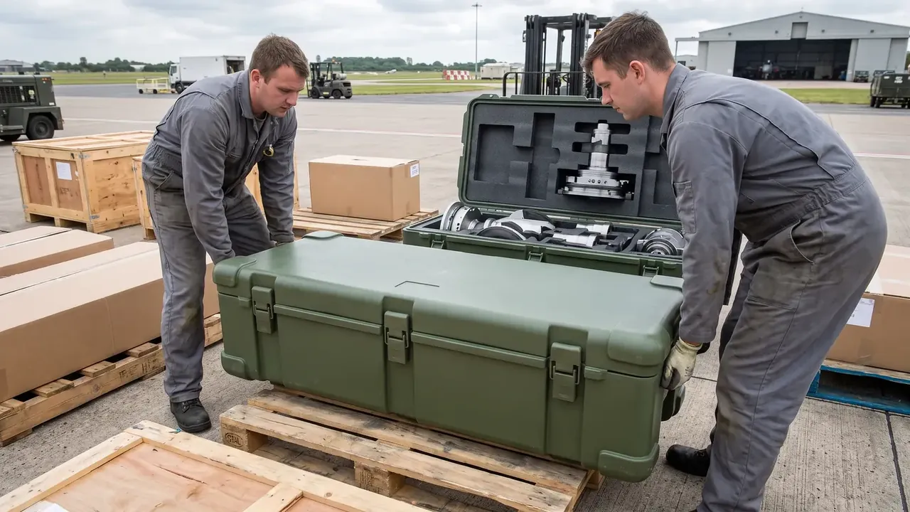
Quick answer: A Military Air Transport Case is judged on five points: the lightweight frame formed by wall thickness and ribs, the margin left for pressure and stacking loads, the number and position of tie-downs, seal recovery across pressure cycles, and the lifting points two handlers can reach.
Table of contents
- How the Lightweight Frame of a Military Air Transport Case Is Built
- Where Load Capacity and Weight Saving Trade Off
- How Many Tie-Down Points and Where
- Sealing Against Cabin Pressure Cycles
- Handling and Stacking Details
- FAQ
1. How the Lightweight Frame of a Military Air Transport Case Is Built
Weight is the hard constraint in air freight. A Military Air Transport Case rotomoulded at a uniform 4.0 mm weighs 16.8 kg empty; thinning non-structural panels to 2.8 mm while keeping corners and floor thick brings it to 14.6 kg, with higher bending stiffness.
| Layer | Material | Size |
|---|---|---|
| Shell | High density polyethylene | 2.8–4.0 mm |
| Frame | 6061-T6 tube | 25 x 25 x 2 mm |
| Rib | Moulded with the shell | 12 mm high, 90 mm pitch |
How the frame joins the shell decides the process. Through-bolts need moulded-in stainless inserts rated 1200 N; bonding tubes onto moulded ribs saves drilling but blocks repair. At 290 °C on a 4:1 biaxial ratio the powder builds evenly, while a wrong ratio leaves a 0.5 mm step at the rib root.
2. Where Load Capacity and Weight Saving Trade Off
A Military Air Transport Case carries three loads at once: cabin differential, stacking weight and handling impact. The wall bulges outward, and past 3 mm the bulge presses into the insert face.
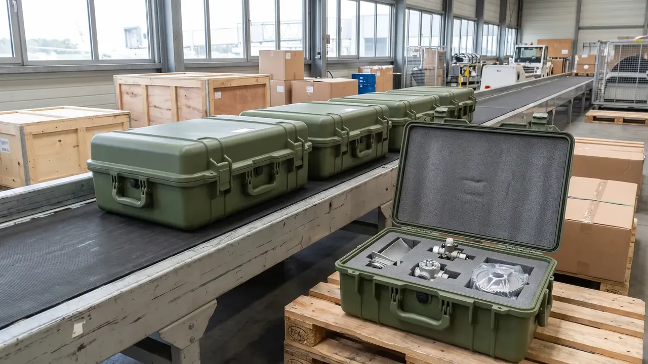
The trade is measurable: taking the side wall from 4.0 mm to 3.0 mm saves 1.4 kg but lifts bulge from 1.8 mm to 3.4 mm at 26 kPa, and each extra rib at 90 mm pitch returns 18% stiffness for 0.3 kg.
| Case | Load | Limit |
|---|---|---|
| Cabin differential | 26 kPa | 3 mm bulge |
| Forward impact | 6 g | No yield at corner |
| Stacking | 180 kg on lid | 2 mm sink |
| Vibration | 1.04 g rms, 1 h per axis | No loosening |
Vibration is the quiet one: sustained micro-motion between parts whose expansion differs threefold leaves white powder around the insert.
3. How Many Tie-Down Points and Where
More points is not better; cabin rails sit at fixed intervals. Four points, set 150 mm from each end and rated 2200 N, cover 6 g forward, and they belong on the corner castings.
Fifty millimetres of movement doubles the load. Move a point inboard and the strap angle flattens, the vertical component dents the wall; at 30 to 45 degrees the pull becomes restraint.
Test rather than draw: hold 2200 N for 60 seconds, keep corner displacement under 1 mm, and treat 0.2 mm residual movement as yield.
4. Sealing Against Cabin Pressure Cycles
The difficulty is not water but the cycle: ground 101 kPa against a cruise cabin of 75 kPa leaves about 26 kPa, so every take-off and landing works the seal once.
EPDM at Shore A 55 with 25% to 30% compression holds that rhythm; below the range it never seats, above it takes a set. At −40 °C it stiffens about 15 Shore points, so compression sits at the top of the range.
An 8 mm groove, 6 mm deep, takes 7 mm square cord without extruding. A relief valve opening at 0.35 bar equalises the case, otherwise the vacuum pulls the seal out of its groove.
5. Handling and Stacking Details
Ground crews lift without tools, so two people manage a Military Air Transport Case. Handles near the centre of gravity keep the lift under 15 degrees; high handles splay the base and shear the latches.
| Item | Practice | Failure mode |
|---|---|---|
| Handle | Near centre of gravity | Base splays, latches shear |
| Lid pad | 5 mm plywood | Stacking marks |
| Stack | Three high, 180 kg on top | Base sink past 2 mm |
| Floor gap | About 10 mm off the pallet | Condensate trapped |
Stack height follows lid strength: at four high the bottom lids set permanently, so the standard stops at three. A floor gap lets condensate drain as the hold swings from −40 °C to 60 °C.
Conclusion
A Military Air Transport Case is a weight, stiffness and sealing problem drawn on one sheet. Frame, wall, tie-downs and seal each decide one failure mode. Get those layers right and the Military Air Transport Case behaves the same on the hundredth flight as on the first.
This article discusses only the container (case body) side of specifications and design intent, and does not cover any handling, loading or use of the contents.
Related Reading
- Standards a military air transport case must meet
- Comparing a military air transport case with alternatives
- Choosing a military supply transport case
- How rotational moulding shapes a case
Related Products
- 8 Series — Gun Cases; Military Equipment Cases; Camera Equipment Cases; Drone Cases; Watch Cases; Knife Cases; First Aid Cases; Electronics Equipment Cases
- WL8-2812 PP Gun Case — model WL8-2812
- All protective cases and toolboxes: 7 series, 158 models