

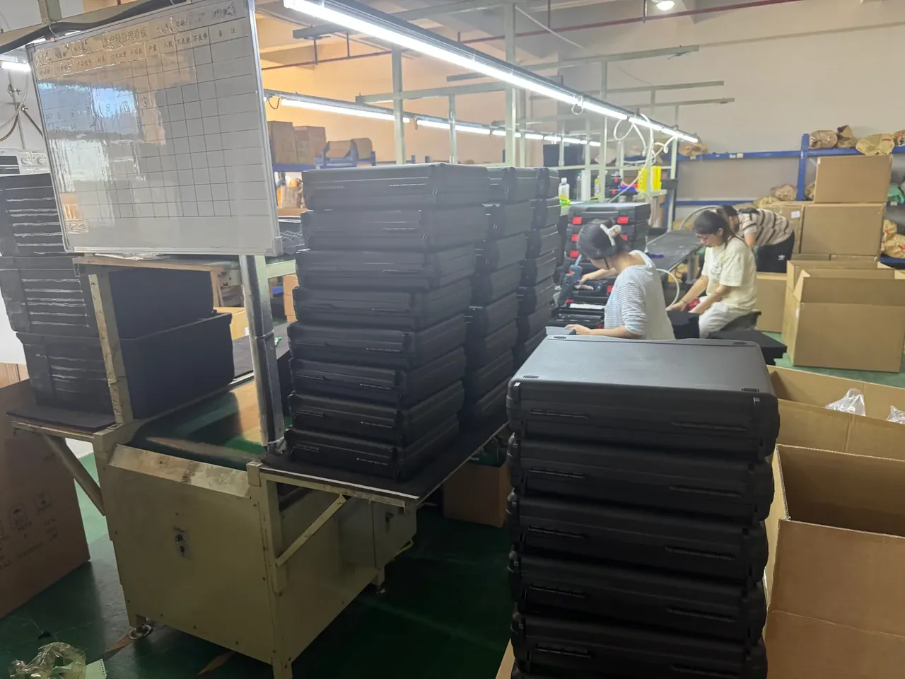
Quick answer: Multi-Size Case Molds run four shell sizes on one base: four locating pins at 0.02 mm, a 45 min insert swap, and five first articles before release.
Table of contents
- Shared Base Envelope and Unified Interfaces
- Interchangeable Inserts and Locating Accuracy
- Insert Swap Time and First-Article Sign-Off
- Quick-Change Couplings on the Cooling Circuit
- Mold Ledger and Shot-Life Records
- FAQ
1. Shared Base Envelope and Unified Interfaces
One base carrying four sizes saves steel, not tolerance. In Multi-Size Case Molds the A and B plates, ejector plate, spacer blocks and guide pillars stay bolted together for every model, while only the cavity and core inserts travel. Because the frame never moves, the interfaces have to be settled once.
Four interfaces matter on Multi-Size Case Molds. Plate thickness sets the parting line, and 0.05 mm of error leaves a visible step around the shell; locating bores are machined to H7; water inlets are standardised to one coupling body and dropped below the feet; ejector positions follow the plate, so an insert cannot move its own push points.
| Shared base interface | Reference part | Allowed deviation |
|---|---|---|
| Plate thickness face | A/B parting faces | 0.05 mm |
| Locating bore | H7 bore | 0.02 mm |
| Water inlet | 1/2 inch coupling | 0.1 mm coaxial |
| Ejector bore | Ejector plate | 0.1 mm |
Deviations are given on two grades. Non-critical mounting faces follow ISO 2768-m, ±0.1 to 0.2 mm per 100 mm. Forming surfaces follow ISO 2768-f, ±0.02 to 0.05 mm per 100 mm. Mixing the two doubles the machining bill and changes nothing in the finished shell.
2. Interchangeable Inserts and Locating Accuracy
Inserts on Multi-Size Case Molds are clocked by locating pins, four to a base, two round pins carrying position and two orienting the insert so it cannot go in backwards. The pin-to-bore fit is H7/m6, a light interference that taps home with a copper mallet and will not fall out on its own. Trial inserts pulled weekly drop back to H7/g6 with clearance under 0.02 mm.

Pin heads carry a 15° to 30° chamfer as a lead-in, which stops a swinging insert from burring the bore mouth. Working length runs 1.2 to 1.5 times the diameter: shorter loses location, longer fights removal. Pins are cut from SKD61-class hot-work steel and induction hardened to HRC 45 to 50.
| Insert swap item | Practice | Verdict |
|---|---|---|
| Locating pin fit | H7/m6 light interference | Refits within 0.02 mm |
| Mating face | Hand-lapped | 0.02 mm feeler will not enter |
| Cavity joint offset | Projector comparison | Within 0.03 mm |
The mating face is the floor everything stands on. Once two halves close, a 0.02 mm feeler is walked around the perimeter; if it enters, the face is not yet lapped and melt will creep through the seam as flash. A flashing insert has to be re-lapped at the next changeover, and the 45 min swap doubles on the spot.
3. Insert Swap Time and First-Article Sign-Off
A swap on Multi-Size Case Molds runs in a fixed order: break six water lines, slacken eight cap screws, lift the old insert, clean the mating face, seat the new one, reconnect water, dry-cycle the clamp three times. A practised fitter finishes in 45 min, and nearly half of that is water, which is why quick couplings are a time item.
First articles from Multi-Size Case Molds are never cut to one. Five come off the press: four covering the cavity positions and a fifth held for re-check. Twelve dimensions are measured — outline length and width, cavity depth, pocket pitch, wall thickness, flatness, seating height. The point is not that one part passes; it is the spread across the four cavities. One position repeating an error means the insert sits crooked; all four drifting together points at mould temperature or packing.
| First-article item | Method | Reject line |
|---|---|---|
| Outline length, width | Caliper or CMM | Beyond ±0.05 mm |
| Cavity depth | Depth micrometer | Beyond ±0.05 mm |
| Flatness | Surface plate and feeler | Beyond 0.08 mm |
| Wall thickness | Ultrasonic gauge | Beyond ±0.05 mm |
The reject line reads: any dimension out by 0.05 mm across the five first articles, and the swap does not enter production. Going back is not simply a re-seat; the first question is whether the insert is oversize or whether it clamped off position.
4. Quick-Change Couplings on the Cooling Circuit
Four sizes on one base means the water cannot be re-plumbed at every changeover. Multi-Size Case Molds carry six coupling sets below the feet on a single 1/2 inch body, rated to 300 psi, with silicone seals spanning -54 °C to 200 °C, so a changeover pushes plugs instead of breaking hose clamps.
Circuit geometry on Multi-Size Case Molds has its own rules. Neighbouring lines sit no further apart than three bore diameters, and each line runs within 2.5 bore diameters of the forming surface. Flow must keep the Reynolds number above 10,000 so the water stays turbulent; a 1/2 inch circuit needs roughly 2.2 gpm, about 8.3 L/min.
Couplings sit recessed into the mould face. A plug standing proud is the first thing a crane hook bends, and a bent sealing face means a leak at the next changeover. O-rings are inspected quarterly and swapped when they harden, flatten or crack.
5. Mold Ledger and Shot-Life Records
Life is counted in shots, and this base is designed for 300,000. The ledger on Multi-Size Case Molds is indexed twice, by base and by insert: the base records cumulative shots, repairs and service points; the insert records its start date, shots run, swap count and the report number of every first article.
Service falls every 50,000 shots — flush the circuits, re-check the locating bores, inspect ejector guidance — with a full overhaul at 300,000. Skip the ledger and the next changeover has no idea how much life is left in the insert on the bench.
One column in the Multi-Size Case Molds ledger is compulsory: the cavity allowance for each new insert. PP shrinks 1.5% to 2.0% along flow and 1.8% to 2.5% across it, so length and width take different factors; the measured result is written back into the ledger and the next insert copies it.
Conclusion
Multi-Size Case Molds save steel, not accuracy: one base across four sizes rests on four locating pins, a 0.02 mm fit and one set of interfaces. A 45 min swap, five first articles and 300,000 shots turn reuse into a procedure. The plate money saved has to go back into insert machining, inspection and a ledger filled in every time, or reuse simply copies one deviation four ways.
Related Reading
Related Products
- 8 Series — Gun Cases; Military Equipment Cases; Camera Equipment Cases; Drone Cases; Watch Cases; Knife Cases; First Aid Cases; Electronics Equipment Cases
- WL8-2812 PP Gun Case — model WL8-2812
- All protective cases and toolboxes: 7 series, 158 models