

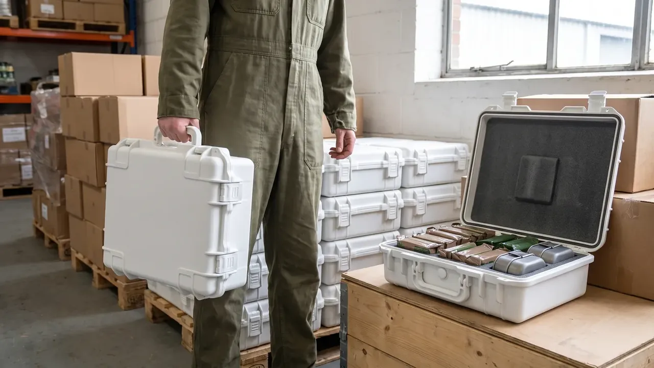
Quick answer: A Photography gear automatic pressure valve case braces a φ20 mm seat at 2.4 N·m, twin lips at 22% compression, passing ±12 kPa and 0.8 m / 30 min.
Table of contents
- Valve-seat opening reinforcement on a Photography gear automatic pressure valve case
- Compression allowance split across the twin-lip mouth seal
- Reading membrane seepage after pressure-difference cycling
- Lid-opening force test points in the post-drop recheck
- Seat torque and the batch air-tightness sampling limit
- FAQ
1. Valve-seat opening reinforcement on a Photography gear automatic pressure valve case
The lid top leaves a φ20 mm opening for the pressure valve, with a reinforcing insert around the rim torqued to 2.4 N·m. A Photography gear automatic pressure valve case measures 560×400×230 mm outside with a 4.2 mm wall; a hole cut straight through thin shell would flare the rim as the insert tightens and warp the lid. A thickened step around the opening spreads the clamping load over a wider area so the torque reading holds steady.
A gasket sits between insert and lid, pressed to a set thickness, with the step face flush to the outer surface. Five lids per batch are checked for rim flatness, and any reading past 0.3 mm returns for tool rework rather than extra torque.
2. Compression allowance split across the twin-lip mouth seal
A Photography gear automatic pressure valve case carries 2 twin-lip seals at the mouth at 22% compression, the ratio of lip height lost to free height with the lid shut. The two lips do not share allowance evenly: the outer one takes more to block soak, the inner one less to leave room for the membrane pressure difference, so a swing does not roll a lip over.
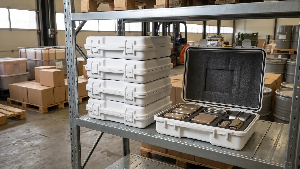
Compression allowance also follows the catches. Two catches at 370 N each pull the lid onto the mouth, and as holding force decays the compression ratio drops, so lip imprint width is read along all four edges after closing; a spread past 0.4 mm sends the allowance back for redistribution.
3. Reading membrane seepage after pressure-difference cycling
The membrane sits inside the seat insert, and reading runs in two steps: a 0.8 m water soak for 30 min first, then seepage after ±12 kPa cycling 200 times. A Photography gear automatic pressure valve case stays shut for the soak, with absorbent paper along the four mouth edges checked for marks at 30 min. Cycling alternates pressure every 50 cycles.
Bands and readings are collected below; a mark in any band returns the batch to seat recheck.
| Pressure-difference band | Cycle count | Membrane state |
|---|---|---|
| +12 kPa | 200 cycles | No seepage |
| −12 kPa | 200 cycles | No seepage |
| ±12 kPa alternating | 200 cycles | No seepage |
| 0 kPa hold | 30 min | Soak control |
A Photography gear automatic pressure valve case ties ±12 kPa to 200 cycles because one pressure step cannot reveal membrane fatigue. The rig reads rim displacement every 50 cycles, retiring a part early if it passes 0.2 mm. Soak depth 0.8 m and dwell 30 min are logged apart: depth sets pressure, dwell sets the seepage window. After a lid drop the part returns to this band for one more reading, confirming the thickened step has not loosened the seat. Air-tightness is benchmarked to the IP67 method with no certificate number listed.
4. Lid-opening force test points in the post-drop recheck
Drops run at 1.0 m; the lid is not opened straight away. Four points on the lid corners are marked and pulled steadily along the opening direction with a force gauge, the peak taken as opening force. A Photography gear automatic pressure valve case sets the judgement at ≤48 N: a higher value means the twin lips were knocked out of line, the 22% compression has drifted, and the 2.4 N·m seat torque may have been levered loose.
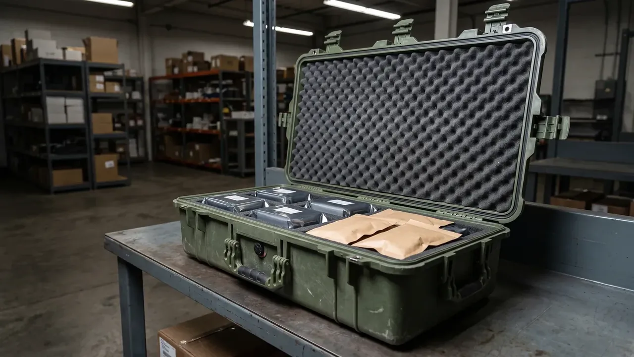
Post-drop seat checks are listed below; a part past the force line is read against this table before any rework.
| Seat part | Drop height | Post-drop check |
|---|---|---|
| Insert rim | 1.0 m | Torque 2.4 N·m |
| Thickened step | 1.0 m | No crack |
| Twin-lip contact face | 1.0 m | Compression 22% |
| Mouth side wall | 1.0 m | Wall 4.2 mm |
Two catches at 370 N each are remeasured after the drop; uneven lid loading inflates the opening force and can misread a good part as out of line.
5. Seat torque and the batch air-tightness sampling limit
Every lid gets its seat insert re-torqued to 2.4 N·m; the sampling limit sits on air-tightness. A Photography gear automatic pressure valve case sends 6 parts per batch through 0.8 m / 30 min soak and 3 more through ±12 kPa / 200 cycles, releasing only when both bands pass. Outer 560×400×230 mm, inner 495×340×175 mm and the 4.2 mm wall are remeasured in the same sampling.
Opening-force bands are judged below, with 48 N as the boundary.
| Force reading | Drop height | Lid judgement |
|---|---|---|
| 38 N | 1.0 m | Pass |
| 44 N | 1.0 m | Pass |
| 48 N | 1.0 m | Boundary |
| 52 N | 1.0 m | Reject |
Release follows batch consistency, not a few passing pieces.
Conclusion
A Photography gear automatic pressure valve case puts φ20 mm seat reinforcement at 2.4 N·m on one side and 22% allowance across 2 twin lips on the other, and the pair governs no seepage at 0.8 m for 30 min plus a dry membrane through ±12 kPa over 200 cycles. A 1.0 m drop is rechecked at ≤48 N opening force, with 2 catches at 370 N each and air-tightness benchmarked to IP67 holding one set of readings. Release follows both air-tightness bands passing, with the torque sheet as reference only.
Related Reading
- Case pressure equalization valve selection
- Case pressure relief valve structure
- Camera equipment case specification guide
- When to fit a case drain valve
Related Products
- 8 Series — Gun Cases; Military Equipment Cases; Camera Equipment Cases; Drone Cases; Watch Cases; Knife Cases; First Aid Cases; Electronics Equipment Cases
- WL8-2812 PP Gun Case — model WL8-2812
- All protective cases and toolboxes: 7 series, 158 models