

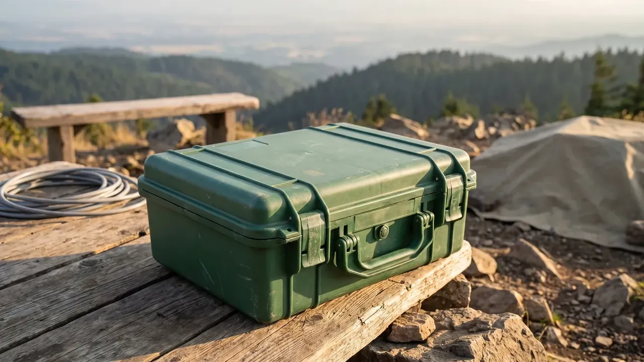
Quick answer: A Rehabilitation Equipment Transport Case 780 mm long rides on four lashing points: a 120 N·m cap, 25 mm webbing, two truck ties and 0.35 m² of contact.
Table of contents
- Long-Load Traits of a Rehabilitation Equipment Transport Case
- Lashing Points and Overturning Moment
- Cavity Depth and Clearance for Odd Shapes
- Contact Area Against the Truck Bed
- Counting Fixings on Arrival
- FAQ
1. Long-Load Traits of a Rehabilitation Equipment Transport Case
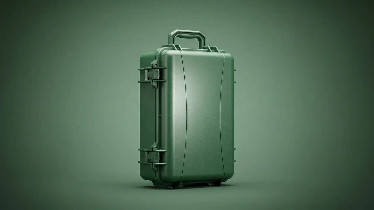
Length rolls a long case over in a truck bed, and the roll depends on which segment the lashing points sit in. A Rehabilitation Equipment Transport Case at 780 × 420 × 300 mm outside, 730 × 370 × 260 mm inside, 5.5 mm of wall and 13.8 kg runs a length-to-width ratio near 1.86, with its mass about 140 mm off the floor.
The difficulty is the lever, not the mass. A square case puts its centre over the middle of the footprint; a long case puts it 210 mm from the side edge, so each brake and each corner turns 13.8 kg into a tipping tendency. Grain in a timber deck changes friction: along the grain it slides, across it grips.
| Lashing point | Distance from the end face | What it carries |
|---|---|---|
| Two end points | Within 120 mm | Blocks fore-and-aft shift under braking |
| Two middle points | Either side of centre | Blocks sway on a corner |
| Single centre point | Cases under 600 mm only | Short arm, one point suffices |
A long case loads right when its base sits flat; otherwise the straps only hang it.
2. Lashing Points and Overturning Moment
The Rehabilitation Equipment Transport Case carries 4 lashing points, two at the ends and two amidships, on 25 mm webbing. The end pair sits within 120 mm of the end face, on the straight run past the corner radius; the middle pair straddles the centre of gravity, so a sideways force has somewhere to go. The four make a quadrangle around the shell. Lose a corner and the other three take about thirty percent more each.
The static sum is short: 13.8 kg on a 210 mm arm gives 28 N·m. A 0.5 g lateral case, dynamic surge and a safety factor take the acceptance cap to 120 N·m, about four times the static figure.
| Overturning moment | Working condition | Response |
|---|---|---|
| Under 28 N·m | Standing, flat push | Points laid out as standard |
| 28 to 80 N·m | Cornering, ramp | Middle pair cinched at the wall |
| 80 to 120 N·m | Hard braking plus a corner | All four loaded, no crossed straps |
At 780 mm the four points must hold the moment under 120 N·m; losing one means recalculating rather than adding a strap, because the remaining three change direction.
Between −25 ℃ and +60 ℃ the webbing changes elongation: in the cold it stiffens, so the preload that holds the Rehabilitation Equipment Transport Case on the deck starts ten percent higher.
3. Cavity Depth and Clearance for Odd Shapes
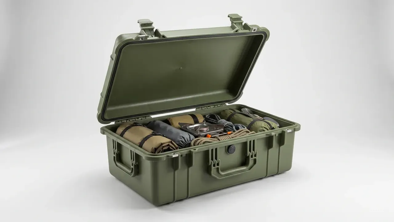
Inside 730 × 370 × 260 mm the insert runs three layers: a flat lid sheet, a die-cut middle, a solid base. The cut goes 180 mm deep, about seventy percent of the cavity, since deeper leaves too little base to absorb a landing and shallower lets the part press the lid.
Clearance is 3 mm, the compromise between picking and holding. Under 2 mm fingers cannot reach and the part will not lift out; over 5 mm the long cavity lets it slide until a corner load lands on the wall. A Rehabilitation Equipment Transport Case lined to 3 mm needs a cold check, where EVA stiffens and the gap feels looser.
The foam is 60 kg/m³ at Shore A25, with compression set to ASTM D3574 at 70 ℃ for 22 h held under five percent. Once the cavity wall collapses, 3 mm becomes 6 mm and the odd shape moves again.
Odd outlines are not cut square. Corners and pipe stubs get a relief pocket 3 mm outside the profile, so a stub drops in rather than pressing the wall; pocket depth is gauged separately.
4. Contact Area Against the Truck Bed
Two ties are the floor for this length, one forward of centre and one aft, spaced at least a third of the case length apart.
Contact under a Rehabilitation Equipment Transport Case spreads to 0.35 m²: 0.33 m² of base on the deck, 0.02 m² of wall on the headboard. At 13.8 kg the pressure stays under 400 Pa and the deck will not dent; the hard spots are the two edges the webbing crosses.
| Contact face | Area | How it is restrained |
|---|---|---|
| Base on deck | 0.33 m² | Friction plus two straps pulling down |
| Side wall on headboard | 0.02 m² | Buttress against sideways travel |
| End face on headboard | Depends on loading position | Only where a front board exists |
Road acceptance takes 0.8 g forward, 0.5 g sideways and rearward, 0.2 g upward, with anchors under 3 m apart. Two ties across 780 mm sit a third of the length apart; push both to one end of a Rehabilitation Equipment Transport Case and the 0.8 g load rides on friction alone.
5. Counting Fixings on Arrival
Nothing is opened on arrival. Three latches are rated 380 N each and the case ships to IP67, 1 m of water for 30 min, so a water line or a shifted latch is noted first.
Count fixings, not parts: 4 straps, 4 buckles, 3 insert blocks, 2 relief pockets. A missing piece means the shell was re-tied en route. In a three-high stack the bottom lid takes a mark, and it belongs on the ribs, not in the gasket groove.
Close the lid and pull each point with 30 N; the Rehabilitation Equipment Transport Case passes only if the ring turns without rocking.
Conclusion
A Rehabilitation Equipment Transport Case settles fixing first and lining second: 4 lashing points divide the 120 N·m overturning moment, 2 ties load the 0.35 m² contact face, and a 180 mm cut only keeps the odd shape where it belongs. Loosen any of the three and the part finds its own direction inside the long cavity.
Related Reading
Related Products
- 8 Series — Gun Cases; Military Equipment Cases; Camera Equipment Cases; Drone Cases; Watch Cases; Knife Cases; First Aid Cases; Electronics Equipment Cases
- WL8-2812 PP Gun Case — model WL8-2812
- All protective cases and toolboxes: 7 series, 158 models