

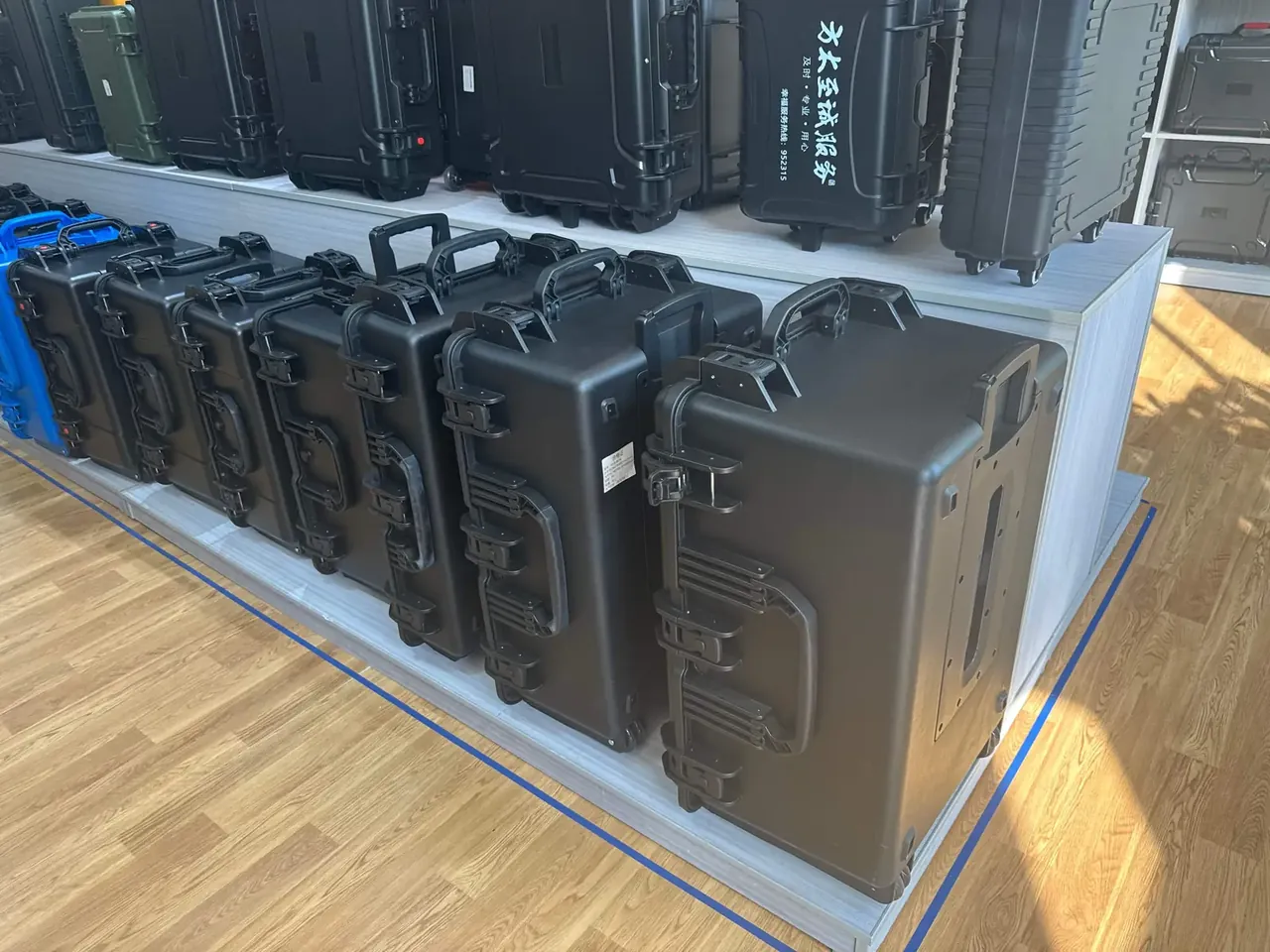
Quick answer: A rotationally molded case is specified in four steps: insert thickness fixes the cavity, cavity plus wall and rib height fixes the envelope, stacking tiers fix the load, and the freight mode fixes sealing. Change that order and every dimension is drawn twice.
Table of contents
- Four steps that fix the specification
- The cavity is set by the insert
- Wall thickness and rib spacing
- Load ratings and stacking arithmetic
- Sealing grade follows the transport mode
- FAQ
1. Four steps that fix the specification
A rotationally molded case has four linked numbers: cavity, envelope, wall and load. The usual mistake is to start with the envelope: draw a 1200 by 800 by 600 mm shell to suit the rack, and lose twenty-odd millimetres of cavity to wall and ribs.
Work from the inside out: payload plus insert gives the cavity, cavity plus wall and rib gives the envelope, tiers give the load, and the freight mode gives the sealing class.
| Item | Set by | Typical | Verify |
|---|---|---|---|
| Cavity | payload plus insert | 6 to 10 mm per side | tape at three points |
| Envelope | cavity plus wall and rib | 12 to 18 mm per side | pallet and truck clearance |
| Wall | tiers and gross weight | 4 to 7 mm | caliper at rib root |
| Latches | perimeter | one per 350 mm | close each and listen |
2. The cavity is set by the insert
The first constraint on a rotationally molded case is the insert, not the payload. Foam only supports when it touches six faces, so the cavity grows by the insert thickness. With 10 mm EVA and a 500 by 300 by 200 mm payload, the cavity needs 532 by 332 by 232 mm, which is 6 mm per side for rebound.
Depth splits between lid foam of 15 to 25 mm and base foam of 20 to 30 mm, so a 200 mm item wants about 250 mm of cavity plus 15 mm per side.
3. Wall thickness and rib spacing
Walls run 4 to 7 mm on most rotationally molded cases. Past 8 mm the shrinkage difference between surfaces grows, sink marks appear on flat panels, and a drop crack starts there, not at a corner. What counts is whether load reaches the four corners along ribs.
Ribs need height, width and spacing: a base grid of 6 to 8 mm high at 80 to 120 mm centres, with wall ribs aligned to the latches. The rib root runs about 1.5 mm thicker than mid-wall, so state it on the drawing. An outer radius under the wall thickness drops measured wall below 3 mm.
4. Load ratings and stacking arithmetic
Catalogue ratings for a rotationally molded case are single-case static load, which is not stacking. Stacking loads the bottom tier: six tiers at 32 kg gross means 160 kg for two years without creep, and a factor of two turns that into a 320 kg design load.
Contact area decides how the load travels: a flat top over a continuous base rim spreads it, a dished top on four feet concentrates it. Keep deflection under 1.5 mm across a 600 mm span.
| Tiers | Static load at 32 kg gross | Design load, factor 2 | Minimum wall |
|---|---|---|---|
| 3 | 64 kg | 128 kg | 4 mm |
| 4 | 96 kg | 192 kg | 4.5 mm |
| 5 | 128 kg | 256 kg | 5 mm |
| 6 | 160 kg | 320 kg | 6 mm |
5. Sealing grade follows the transport mode
Sealing on a rotationally molded case should match the journey: IP65 for a short road leg, IP67 plus a pressure valve for sea freight swinging from 5 to 45 °C, and a valve on air freight, where 60 kPa sucks the lid down and pulls the gasket from its groove.
Test by immersion, one metre for thirty minutes, or by pressure decay: charge to 20 kPa and lose under 1 kPa in five. Decay leaves a number, so use it for batch deliveries.
| Mode | Swing | Sealing | Valve |
|---|---|---|---|
| Road | 10 to 35 °C | IP65 | no |
| Sea | 5 to 45 °C | IP67 | yes |
| Air | -20 to 30 °C | IP67 | mandatory |
Conclusion
A rotationally molded case is specified from the inside out: insert to cavity, cavity to envelope, tiers to load, freight mode to sealing. Each step ends in something measurable, not a catalogue figure. Ask about tiers and freight mode before wall thickness on a rotationally molded case.
This article discusses only the container (case body) side of specifications and design intent, and does not cover any handling, loading or use of the contents.
Related Reading
- Choosing a rotationally molded case from the load back
- Specifying a rotomolded case: size, wall, load
- Weather resistance and long-term care
- Where military rotomolded cases are used
Related Products
- 8 Series — Gun Cases; Military Equipment Cases; Camera Equipment Cases; Drone Cases; Watch Cases; Knife Cases; First Aid Cases; Electronics Equipment Cases
- WL8-2812 PP Gun Case — model WL8-2812
- All protective cases and toolboxes: 7 series, 158 models