

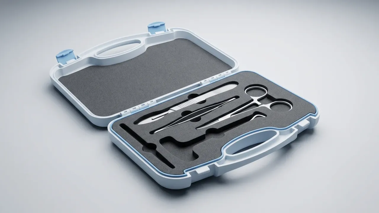
Quick answer: Acceptance of a Shockproof plastic instrument case is judged at the instrument mounting face, not at the shell. Three channels go on the table, the case base and the mounting face; a transmissibility above 3 fails, and the shock run is a 15 g, 11 ms half-sine on three axes.
Table of contents
- Three Layers of Criteria
- Mount It on the Instrument Face
- Sweep 20 to 200 Hz
- Shock at 15 g, 11 ms
- Sealing and Condensation Checks
- Three Routes for a Failed Unit
- FAQ
1. Three Layers of Criteria
Most failed negotiations start with three layers collapsed into one phrase about the standard. The environmental standard sets tests and severity, the method standard sets mounting and sampling, the contract sets sample size and disposition.
| Layer | Typical documents | What it fixes |
|---|---|---|
| Environmental | GJB 150.16A, MIL-STD-810H | Tests and severity |
| Method | IEC 60068-2-27, 60068-2-64 | Mounting, sweep, sampling |
| Ingress | IEC 60529, IP67 | Dust and short immersion |
| Delivery | Contract annex, drawing notes | Sampling, pass mark |
The usual gap is the third layer. A report stating the unit functioned normally, with no mounting-face peak and no transmissibility figure, reads as both a pass and a fail.
2. Mount It on the Instrument Face
Pick the wrong point and everything downstream is wasted. Shell response depends on ribs and the gasket groove, so spots on the same shell differ by 40 percent; the instrument is loaded where it meets the insert.
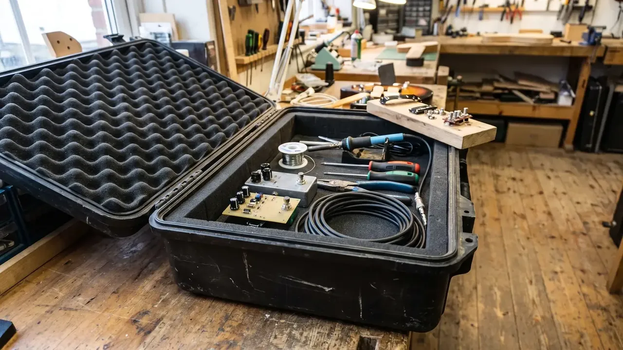
Three channels divide the work: table as input reference, case base for structural response, mounting face for the verdict. Keep a service loop in the cable; a taut lead transmits force.
Sample at 10 kHz or above, anti-alias filter at 0.4 times the rate, both in the report.
| Channel | Position | Range | Role |
|---|---|---|---|
| CH1 | Table | 50 g | Input spectrum |
| CH2 | Case base | 200 g | Structural gain |
| CH3 | Mounting face | 500 g | Pass or fail |
Calibrate the three sensors as one batch at 10 mV per g; mixed batches bias transmissibility by more than 10 percent.
3. Sweep 20 to 200 Hz
Road energy sits between 20 and 200 Hz: suspension at 2 to 8 Hz, floor panels at 10 to 20 Hz, frame coupling at 60 to 200 Hz. A resonance of the Shockproof plastic instrument case in that band is amplified on every kilometre.
Sweep 5 to 500 Hz at one octave per minute, 0.5 g input, one pass per axis. The pass mark is a transmissibility of 3 or less at resonance; above that the insert has stopped isolating.
Resonance needs a dwell: 10 minutes either side of the peak, then sweep again. A shift above 10 percent means foam compaction or a loosened latch.
4. Shock at 15 g, 11 ms
Shock runs as a half-sine at 15 g and 11 ms, three shocks in each direction on three axes, 18 in total. That matches roughly a 0.8 m drop, the common event at a tail lift.
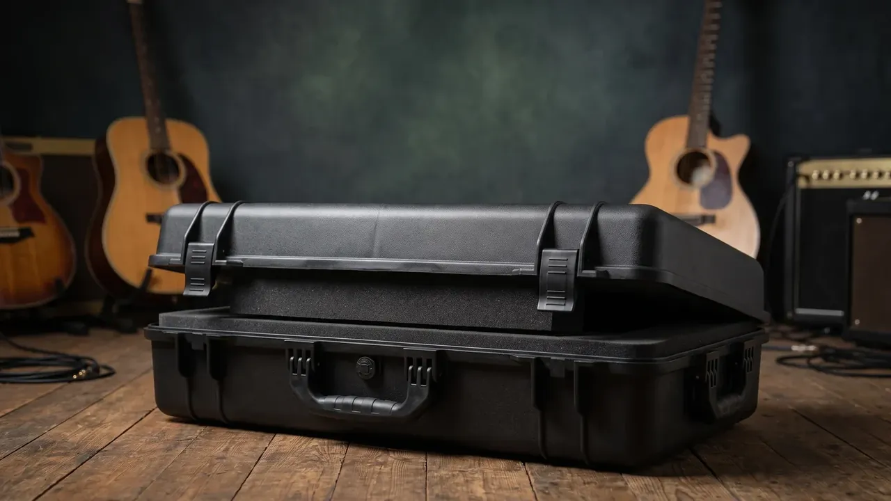
Three conditions hold together: mounting-face peak under the instrument limit, insert set under 1 mm, latches and hinges intact.
With a 40 g instrument limit, a 15 g input leaves 2.6 times margin; an insert that amplifies the peak to 45 g turns that margin negative. Strip the insert afterwards: crushed foam cells and a base pad down from 15 to 12 mm count as set.
An intact shell with an over-limit mounting face accounts for over half the failures in practice: a cargo case is judged on cracks, an instrument case on the g-forces it passed on.
5. Sealing and Condensation Checks
Vibration is not the only risk. Sealing is checked to IP67: hold 20 kPa for 60 seconds with no more than 0.3 kPa drop, or immerse 1 m for 30 minutes. Gasket compression stays at 25 to 30 percent; at 50 it seals this year and not the next.
Condensation hides better. Run five cycles between −20 °C and 55 °C at four hours each, then require no water marks and under 0.5 percent insert growth; a 0.1 mm gasket gap lets moisture in within a day.
Pressure valves are the blind spot: a relief valve can leak at 20 kPa alone, so plug it and test the shell, or test the valve.
6. Three Routes for a Failed Unit
A failure is not automatically a rejection. Sort by defect type and record every case.
- Rework: transmissibility 3 to 5 with an intact shell; insert density 45 to 60 kg per cubic metre, base pad 8 to 15 mm
- Concession: transmissibility above 3 with a delivery radius under 300 km; cut the load 20 percent, mark it restricted, get written acceptance
- Rejection: transmissibility above 5, a through-crack, or a latch that opens during shock
- Records: unit number, sensor position, spectra and shock traces kept for three years
Write those boundaries into the contract. Say only that failures are returned, and every problem drifts toward concession.
Conclusion
Acceptance of a Shockproof plastic instrument case rests on mounting-face acceleration, not on a report paragraph. Three layers set the tests, sensor position sets the truth, transmissibility sets the verdict, three routes set what follows for the Shockproof plastic instrument case.
This article discusses only the container (case body) side of specifications and design intent, and does not cover any handling, loading or use of the contents.
Related Reading
- Instrument case product range
- Specifications for custom foam inserts
- Packing detection instruments on site
- Size steps across the instrument box series
Related Products
- 8 Series — Gun Cases; Military Equipment Cases; Camera Equipment Cases; Drone Cases; Watch Cases; Knife Cases; First Aid Cases; Electronics Equipment Cases
- WL8-2812 PP Gun Case — model WL8-2812
- All protective cases and toolboxes: 7 series, 158 models