


Precision instruments are a special class of cargo. The purchase price may not be the highest, but once an instrument loses accuracy in transit, the loss usually exceeds the device itself: field readings become void, batch decisions lose their basis, and the downtime for re-testing and recalibration cannot be recovered. The harder problem is that damage often does not show as a cracked housing. It shows as zero-point drift, non-linearity at the end of the range, or micro-cracking in a probe element, none of which is visible when the case is opened. The design target for an instrument case is therefore not simply surviving a drop, but preserving traceable metrological performance on arrival.
The core of an instrument case is not a harder shell; it is translating the acceleration, temperature swing and humidity limits an instrument can tolerate into three verifiable structural parameters: cushion thickness, compartment layout and sealing class. JUNZHIJIA designs instrument cases on exactly this logic: obtain the fragility, weight, center of gravity and interface dimensions of the instrument first, work backward to the cushion structure, and verify with transport testing and arrival recalibration together.
Table of Contents
- Four Damage Paths in Precision Instrument Transport
- Design Baseline and Structure of JUNZHIJIA Instrument Cases
- Fragility, G-Level and Cushion Thickness: Designing Backwards from the Instrument Limit
- Cushion Material Selection: EVA, PE, PU and IXPE Trade-Offs
- Compartmentalization: Independently Fixing Instrument, Probe, Cable and Power Supply
- Sealing and Humidity Control: IP Rating, Desiccant and Humidity Indicator
- Pressure Equalization Valve: Seal Protection for Air Freight and High Altitude
- Temperature, Drift and Recalibration: Metrological Criteria After Transport
- Static and Electromagnetic: ESD Surface Resistance and Shielding Liners
- Transport Test Matrix: ISTA, ASTM D4169 and GB/T 4857
- Coastal and Ocean Routes: Evaluation Limits of GB/T 10125 Salt Spray
- Field Efficiency and Selection Checklist: Latches, Hinges, Handles and Configurations
- Documentation, Seals and Serial Number Traceability
- Frequently Asked Questions FAQ
- Conclusion and Related Reading
Four Damage Paths in Precision Instrument Transport
Instrument damage paths differ from those of ordinary equipment. Ordinary equipment fears high-energy impact, while instruments fear three quieter inputs: low-amplitude high-frequency vibration, temperature and humidity cycling, and electrostatic discharge. The first is impact acceleration beyond limit. Instruments contain cantilevered sensors, quartz crystals or thin diaphragms whose allowable acceleration runs from 15 g to 40 g, far below ordinary equipment, so a drop exceeding 100 g reaches the sensor body directly. The second is resonance amplification. When transport vibration lands near the natural frequency of the instrument or cushion system, response is amplified three to ten times and prolonged exposure fatigues solder joints. The third is temperature and humidity: optical, piezoelectric and circuit board components are moisture sensitive, condensation raises leakage current and shifts zero points, and heat accelerates seal aging. The fourth is static discharge, since an unprotected plastic case can generate several kilovolts of triboelectric charge in a dry environment, enough to damage sensitive input stages.
| Damage Path | Input Form | Typical Threshold | Structural Countermeasure |
|---|---|---|---|
| --- | --- | --- | --- |
| Impact beyond limit | Drops, handling shocks | Allowable acceleration 15 to 40 g | Cushion thickness, limiting structure |
| Resonance amplification | Road and rail vibration | Critical band 5 to 50 Hz | Tune natural frequency, layered cushion |
| Temperature and humidity | Daily cycling, humid sea freight | Risk above 60 percent relative humidity | Desiccant, sealing, indicator card |
| Electrostatic discharge | Dry friction, packing materials | Sensitive device threshold below 2 kV | Conductive liner, ground path |
Deciding which path dominates requires two data sets: the manufacturer allowable acceleration and sensitive-device class, and the actual vibration and drop severity of the logistics chain. Related differences are covered in shockproof toolbox for precision tools.
Design Baseline and Structure of JUNZHIJIA Instrument Cases
The structural baseline of an instrument case has five parts: the shell, the cushion liner, the compartment and limiting inserts, the seal interface, and the metal closure hardware. The shell resists external impact and stacking load, the liner absorbs impact energy down to a level the instrument can accept, the inserts prevent movement inside the case, the seal interface blocks moisture and dust, and the hardware keeps the case closed under vibration.
Shell material follows the application. Medium and large cases are mainly rotomolded low-density polyethylene with 4 to 8 mm walls, offering good low-temperature impact performance for instruments weighing 20 to 60 kg. Small and medium cases can use injection-molded polypropylene copolymer, which holds tighter tolerances and supports finer compartment geometry. Where an instrument carries precision guideways or an optical reference surface, an aluminum frame offers high stiffness and low thermal distortion at higher weight and cost.
| Component | Primary Function | Key Parameters | Common Mistake |
|---|---|---|---|
| --- | --- | --- | --- |
| Shell | External load, stacking, seal support | Wall thickness, ribs, flatness | Thinning corners to save weight |
| Cushion liner | Absorb impact energy | Density, thickness, compression curve | Single density throughout |
| Compartment inserts | Limit displacement | Clearance, support points | Relying on foam clamping alone |
| Seal interface | Moisture and dust barrier | Compression, channel tolerance | Channel tolerance too loose |
| Closure hardware | Maintain closure | Latch retention, hinge life | Too few latches |
Cushion liner and shell must be designed together, because dropping generic foam into a standard case often places the peak of the cushion curve right at the instrument natural frequency and amplifies vibration instead of damping it. The JUNZHIJIA method fixes liner zones by center of gravity and weight, selects density per zone, and verifies with drop and vibration testing. A comparable architecture is described in precision instrument protective case.
Fragility, G-Level and Cushion Thickness: Designing Backwards from the Instrument Limit
Cushion design should start from fragility, not from foam thickness. Fragility, expressed as a G value, is the maximum acceleration an instrument survives without functional failure. Most precision instruments sit at 25 to 40 G, and units with quartz crystals or glass optics may be as low as 15 to 20 G. The peak acceleration of a drop depends on drop height and landing surface stiffness, and the entire design goal is to bring that peak below the fragility value.
The governing relationship is conservation of energy: the potential energy released by the drop is absorbed by compression of the cushion. In practice the cushion curve method is more common, reading the peak acceleration curve for the material at the relevant static stress and selecting the stress near the low point of that curve as the design point. Static stress is instrument weight divided by liner bearing area. Choose it too high and the foam compacts early, making peak acceleration climb sharply; too low and the foam is too soft, letting the instrument travel far enough to strike the limiting inserts.
| Instrument Weight | Drop Height | Allowable Acceleration | Recommended Liner Thickness | Recommended Foam Density | Static Stress Design Point |
|---|---|---|---|---|---|
| --- | --- | --- | --- | --- | --- |
| 2 kg | 0.8 m | 40 G | 25 to 35 mm | 25 to 35 kg/m3 | 3 to 5 kPa |
| 5 kg | 0.8 m | 30 G | 40 to 55 mm | 30 to 45 kg/m3 | 4 to 7 kPa |
| 10 kg | 0.6 m | 25 G | 50 to 65 mm | 35 to 50 kg/m3 | 6 to 10 kPa |
| 20 kg | 0.6 m | 20 G | 65 to 85 mm | 45 to 60 kg/m3 | 8 to 14 kPa |
| 40 kg | 0.4 m | 20 G | 70 to 95 mm | 55 to 70 kg/m3 | 10 to 18 kPa |
Cushion thickness and bearing area must be fixed together, because at the same thickness a larger bearing area lowers static stress and vice versa, and this pair determines both the liner shape and the feasible compartment layout.
Cushion Material Selection: EVA, PE, PU and IXPE Trade-Offs
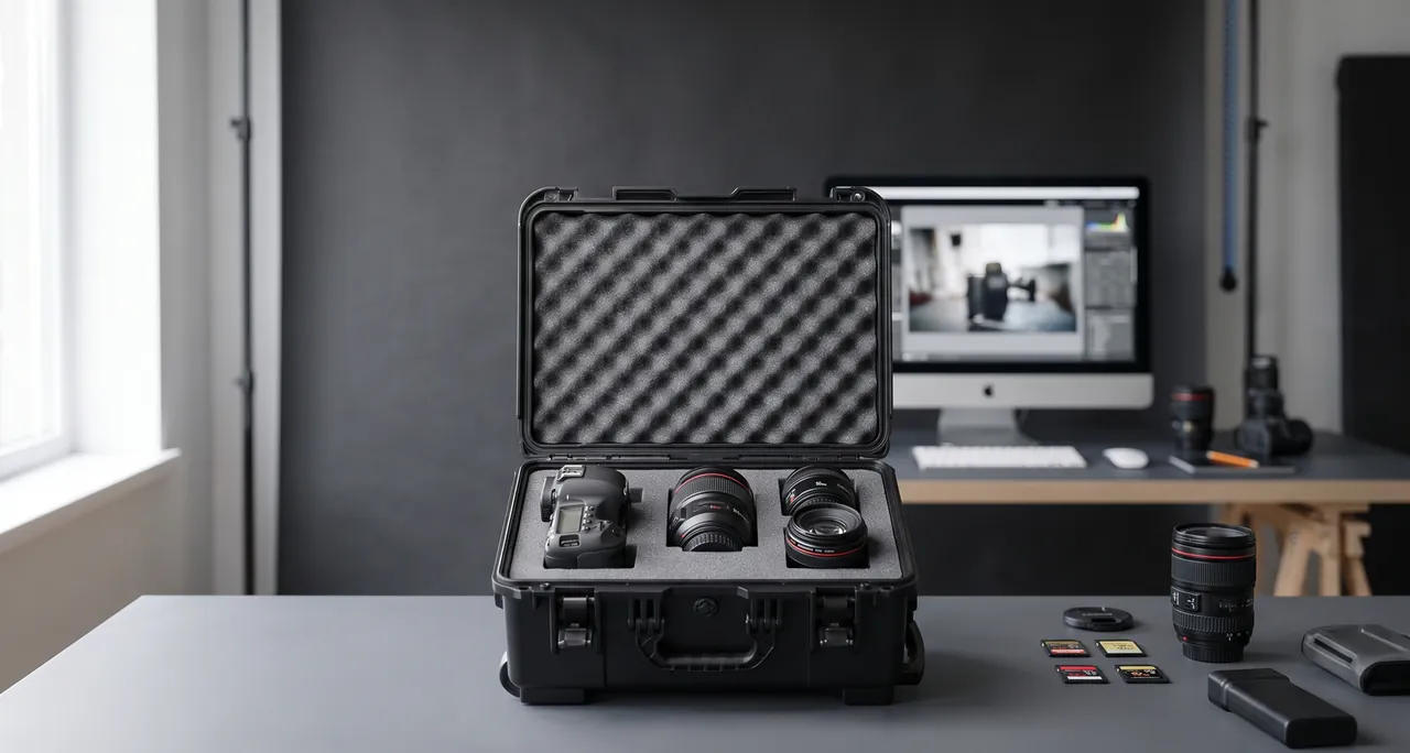
Cushion material selection balances four indicators: energy absorption per unit volume, compression set, rebound speed and processability. Fast-rebounding materials perform better across repeated drops, while slow-rebounding materials absorb more energy in a single impact but may compact permanently after one event.
| Material | Density Range | Energy Absorption | Compression Set | Processability | Typical Use |
|---|---|---|---|---|---|
| --- | --- | --- | --- | --- | --- |
| EVA copolymer foam | 25 to 90 kg/m3 | Medium-high, good rebound | Low | Die-cut and laminate | Main cushion, compartments |
| PE foam | 20 to 60 kg/m3 | Medium, slightly stiffer | Medium | Die-cut | Large supports, base pads |
| PU foam | 20 to 50 kg/m3 | High, soft | Medium-high | Laminate | Surface contact layer |
| IXPE crosslinked PE | 30 to 80 kg/m3 | High, closed cell | Low | Thermoforming required | Thin high-absorption layers |
| EPP bead foam | 20 to 60 kg/m3 | High, stable over cycles | Very low | Tooling required | High-cycle applications |
Single-layer liners are rarely optimal. A common JUNZHIJIA build uses 30 to 45 kg/m3 PE foam on the outside to handle large displacement and initial energy absorption, a slightly denser EVA layer for the main absorption, and a soft PU or flocked EVA contact layer against the instrument so hard foam does not leave impressions. Density is not a simple case of denser being better, since higher density raises load capacity but also peak acceleration at the same static stress. The right approach is to find the static stress band that minimizes peak acceleration at the given thickness, then choose the density that places the design point inside that band. Comparison methods are described in case foam material comparison.
Compartmentalization: Independently Fixing Instrument, Probe, Cable and Power Supply
Compartmentalization is what separates an instrument case from a general protective case. A precision instrument usually consists of a main unit, a probe or sensor, a dedicated cable, a power adapter, calibration accessories and documentation, each with very different weight, stiffness and tolerance. Packed into one cavity, the heaviest item becomes a hammer under impact, repeatedly striking the most fragile one.
Compartment design follows three rules. Heavy items sit near the projection of the case center of gravity, reducing secondary impact from rotational inertia. Hardware and delicate items are separated, so probes and optical accessories need their own cavity and must not share space with a metal housing. The limiting inserts in each cavity must locate in all three axes, since foam clamping alone will not resist longitudinal shock.
| Component | Sensitivity | Fixing Method | Allowable Clearance | Protection Focus |
|---|---|---|---|---|
| --- | --- | --- | --- | --- |
| Main unit | Impact, vibration | Mating foam plus side stops | 2 mm or less | Keep bearing off connector panel |
| Probe or sensor | Impact, static | Separate cavity with soft lining | 1 mm or less | Sensitive face away from hard foam |
| Dedicated cable | Bending, tension | Spool or figure-eight channel | Free | Bend radius at least 5 times diameter |
| Power adapter | Impact | Separate cavity with stops | 2 mm or less | Pins facing up, unloaded |
| Calibration accessories | Temperature, static | Separate hard box plus desiccant | 1 mm or less | Stored at the same temperature |
Cable handling is often overlooked, because under impact a cable whips like a rope and the connector takes the tensile load, eventually breaking conductors inside the jacket. A spool or figure-eight channel that secures the cable to the case wall while maintaining minimum bend radius cuts this failure mode sharply. Related liner fabrication is covered in EVA foam insert custom process.
Sealing and Humidity Control: IP Rating, Desiccant and Humidity Indicator
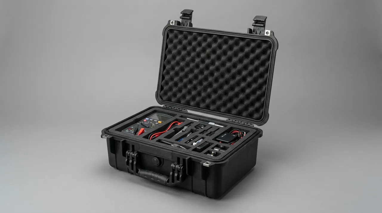
Precision instruments are far more humidity sensitive than ordinary equipment. Above roughly 60 percent relative humidity, optical surfaces can develop fungal growth, ionic residue on circuit boards absorbs water and forms leakage paths, and piezoelectric elements can drift through inter-electrode leakage. The sealing target is therefore not just splash resistance but maintenance of a low-humidity internal environment.
Protection ratings follow IEC 60529 and GB/T 4208. IP65 resists water jets and suits handling stages with rain cover, while IP67 permits short immersion and suits open-air transfer and vessel deck handling. An IP rating describes resistance to ingress of external media, not the humidity inside the case, so maintaining low internal humidity over long transport requires desiccant together with an indicator card.
| Transport Duration | Case Volume | Recommended Desiccant | Indicator Cards | Inspection Requirement |
|---|---|---|---|---|
| --- | --- | --- | --- | --- |
| Up to 7 days | 20 L | 30 to 50 g | 1, visible position | Read on arrival |
| 15 days | 20 L | 60 to 90 g | 1, visible position | Mid-route and arrival |
| 30 days | 20 L | 120 to 160 g | 2, diagonally placed | Weekly and arrival |
| 60-day sea freight | 40 L | 300 to 400 g | 2, diagonally placed | Weekly and arrival |
| Tropical humid route | 40 L | 400 to 500 g | 3 | Weekly and arrival |
Desiccant quantity depends on case volume, transport duration, sealing class and route climate; the table gives starting values for ambient pressure with good sealing. Desiccant should sit where air can circulate rather than wrapped in foam, and the indicator card should be visible at first opening. Seal condition determines whether any of this works, so gasket compression should stay at 20 to 30 percent of section height. Troubleshooting is described in case seal aging.
Pressure Equalization Valve: Seal Protection for Air Freight and High Altitude
The better a case seals, the more it needs a pressure equalization valve. Moving from ambient pressure to a high-altitude site or into an air freight hold can drop external pressure by 20 to 30 kPa. In a fully sealed case, that differential acts across the whole lid area: on a 600 x 400 mm lid the added force can exceed 7,000 N, enough to visibly deform the lid and press the gasket against one side of its channel, creating a temporary leak path.
A pressure equalization valve opens at its set differential and closes again as it falls. Three parameters matter at selection: cracking pressure, venting rate and protection rating. Cracking pressure typically runs 2 to 10 kPa; set too low the case breathes constantly under normal temperature swings and admits more moisture, set too high it provides no protection.
| Parameter | Typical Value | Effect | Selection Guidance |
|---|---|---|---|
| --- | --- | --- | --- |
| Cracking pressure | 2 to 10 kPa | Low vents easily, high may fail to protect | Match maximum pressure change rate |
| Protection rating | IP65 or IP67 | Determines ingress risk | Not below the declared case rating |
| Mounting position | Lid or upper side wall | Affects venting path | Avoid foam-covered zones |
| Membrane material | Expanded PTFE | Waterproof and breathable | Handles dust and oil mist |
Mounting position matters too, since the valve should sit where internal air can reach it freely; if the liner completely covers it, venting efficiency falls sharply. Where a case holds a main unit under mating foam, a vent channel should be molded into the corresponding foam position. The valve is a wear item whose membrane ages with time and contamination, and it belongs on the annual inspection list. Structure and failure criteria are covered in case pressure equalization valve.
Temperature, Drift and Recalibration: Metrological Criteria After Transport
Temperature is the other main influence in transit. Instruments combine materials with different thermal expansion coefficients, and cycling produces zero-point drift and end-of-range error. The temperature coefficient of most precision instruments runs from 0.001 to 0.01 percent of full scale per degree Celsius, which looks small, but after cycling between minus 20 and plus 60 degrees the accumulated drift can reach the edge of the calibration tolerance.
Deciding whether recalibration is needed should follow explicit arrival criteria rather than a feeling. Three criteria are recommended: whether the maximum and minimum temperatures recorded inside the case stayed within the instrument operating range; whether the stabilization time on arrival was sufficient, typically 4 to 8 hours per 10 kg of mass; and whether readings at the verification points fall within the maximum permissible error stated on the calibration certificate.
| Criterion | Data Source | Acceptable Limit | Action if Exceeded |
|---|---|---|---|
| --- | --- | --- | --- |
| Temperature extremes | Temperature and humidity logger | Within instrument range | Send for recalibration |
| Arrival temperature and humidity | Read immediately on opening | No judgement before stabilization | Re-test after stabilization |
| Zero reading | Comparison against standard | Within certificate error | Adjust or recalibrate |
| End-of-range reading | Comparison against standard | As above | Adjust or recalibrate |
| Seal and appearance | Visual plus humidity card | No ingress, no deformation | Record and trace |
These criteria should be agreed in the purchase contract or technical agreement in advance. If a contract only says "acceptable on arrival", a drift dispute leaves both parties working from different definitions of acceptable, and responsibility cannot be assigned.
Static and Electromagnetic: ESD Surface Resistance and Shielding Liners
Precision instruments with sensor input stages are static sensitive. A few tens of volts can damage some field-effect input stages, while ordinary plastic cases in a dry environment can generate several kilovolts of charge, so the liner material needs dedicated ESD attention.
The core indicator is surface resistance. By common convention, conductive materials sit at 10^4 to 10^6 ohms, static dissipative materials at 10^6 to 10^9 ohms, and insulating materials above 10^12 ohms. Instrument cases generally use the dissipative class, which bleeds charge slowly without producing a large current at discharge, achieved with conductive or dissipative EVA and PE foams or with a conductive fabric laminated onto the liner surface.
| Liner Type | Surface Resistance | Discharge Behaviour | Suitable Application | Note |
|---|---|---|---|---|
| --- | --- | --- | --- | --- |
| Standard EVA | Above 10^12 ohms | No dissipation | No static-sensitive parts | Lowest cost |
| Dissipative EVA | 10^6 to 10^9 ohms | Slow dissipation | General electronic instruments | Most common |
| Conductive foam | 10^4 to 10^6 ohms | Fast dissipation | Highly sensitive input stages | Needs a ground path |
| Conductive fabric | 10^5 to 10^8 ohms | Slow dissipation | Surface contact layer | Easy to clean |
| Metallized shield | Low sheet resistance | Also electromagnetic shielding | Instruments with RF modules | Requires isolated grounding |
The case itself is insulating plastic, so the liner must be bonded to an external metal part through a conductive snap or metal hardware, and operators should wear a wrist strap during packing. For instruments that also contain radio frequency modules, a metallized layer can be added outside the liner, but the connection between shield and signal ground must be designed carefully to avoid antenna effects.
Transport Test Matrix: ISTA, ASTM D4169 and GB/T 4857
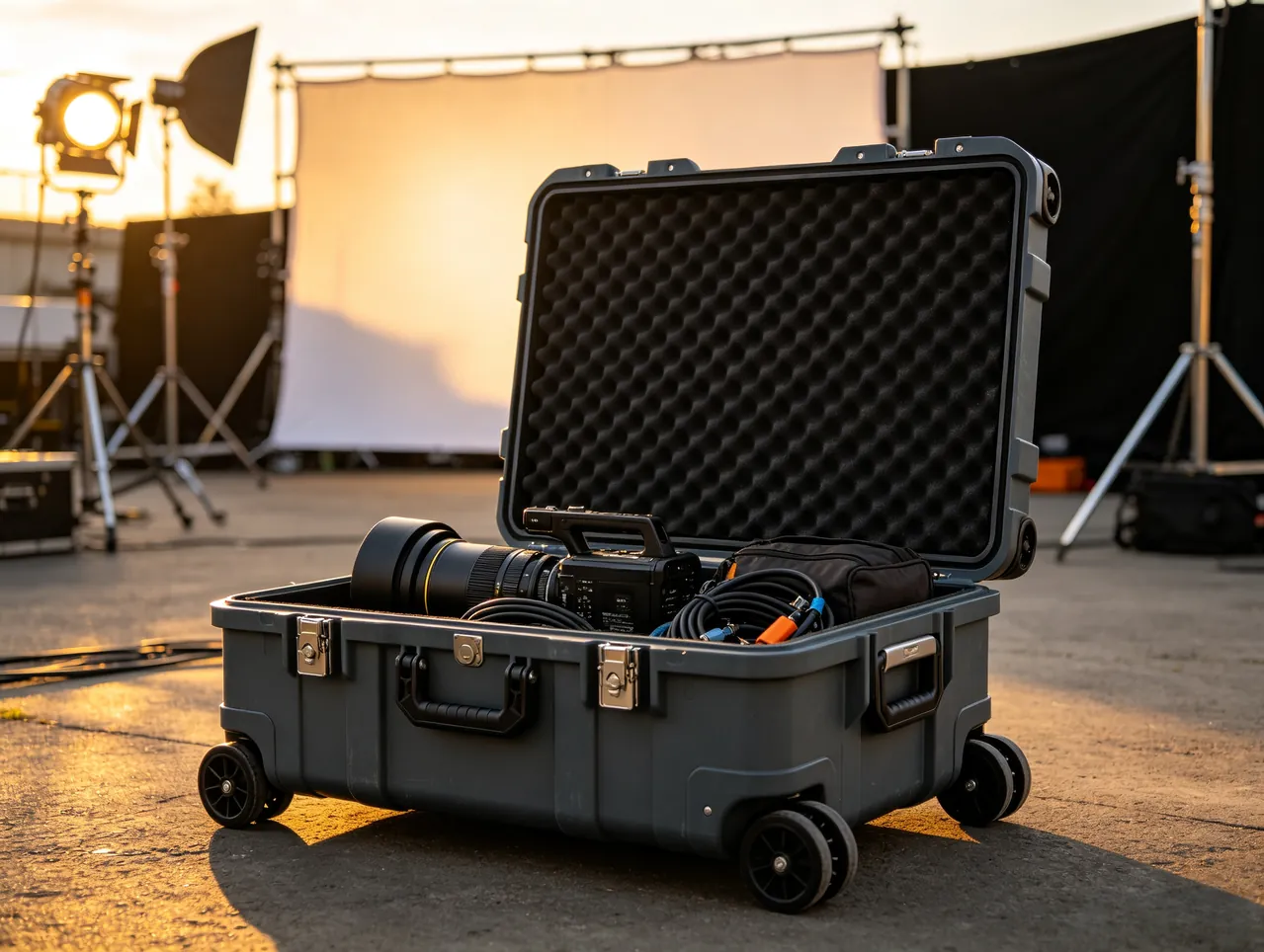
Instrument cases cannot be validated with a single drop test. The sound approach builds a test matrix from the actual logistics chain, covering handling, road, rail, air and storage inputs item by item. The commonly used standards families are ISTA, ASTM D4169 and GB/T 4857, each suited to different situations.
| Test Item | Reference | Simulated Stage | Instrument Focus |
|---|---|---|---|
| --- | --- | --- | --- |
| Free drop | GB/T 4857.5 / ISTA | Manual handling, sorting | Peak acceleration below fragility |
| Random vibration | GB/T 4857.23 | Road and rail transport | Resonance amplification |
| Fixed-frequency vibration | GB/T 4857.7 | Sustained vibration | Fastener loosening |
| Stacking | GB/T 4857.3 | Storage and palletizing | Case deformation, instrument load |
| Low pressure | ASTM D4169 procedures | Air freight, high altitude | Sealing and equalization valve |
| Temperature and humidity cycling | GB/T 2423 series | Climatic environment | Zero drift and condensation |
Drop height should follow actual handling conditions rather than a blanket 1.2 m. Manual carrying, mechanical handling and air freight transfer differ widely: parcel sorting may call for verification at 0.8 to 1.0 m, while palletized movement can be verified at 0.3 to 0.5 m. Accelerometers should be placed at defined liner positions during the test to record the shock waveform and compare it directly with instrument fragility rather than checking external damage alone.
Vibration testing needs frequency attention as well, because road transport energy concentrates between 5 and 50 Hz, exactly the band covering the natural frequency of a small instrument plus liner system. After testing, instrument readings should be re-measured rather than only checking structural integrity, and limits of validity should be written into the technical agreement, since changing liner material, compartment layout or instrument model invalidates the results.
Coastal and Ocean Routes: Evaluation Limits of GB/T 10125 Salt Spray
Coastal storage and ocean transport combine high humidity with a saline atmosphere, placing the heaviest corrosion pressure on case hardware. Latches, hinges, equalization valves and handles usually contain metal parts, and with insufficient plating they develop red rust within months, degrading both feel and seal compression.
Salt spray testing follows GB/T 10125, the common neutral condition using 5 percent sodium chloride solution at 35 degrees Celsius with continuous spraying. Results are reported as time to corrosion or as corroded area ratio. For instrument cases, hardware should be evaluated individually rather than testing the whole case, because plastic parts do not participate in corrosion and a whole-case test only reflects hardware behaviour.
| Hardware | Common Material | Salt Spray Behaviour | Recommended Application |
|---|---|---|---|
| --- | --- | --- | --- |
| Latch | Zinc-plated steel | Fair | Dry inland environments |
| Latch | 304 stainless steel | Good | Coastal, general sea freight |
| Latch | 316 stainless steel | Excellent | Ocean routes, chemical sites |
| Hinge pin | Stainless steel with nylon bushings | Good | High-cycle opening |
| Valve membrane | Expanded PTFE | Excellent | All applications |
The limits of salt spray results must be stated clearly. Salt spray testing ranks options against one another; it cannot be converted directly into field service life and does not support a claim of a specific number of corrosion-free years, because salt deposition, wet-dry cycling and temperature change the corrosion rate. Where a project specifies a life requirement, the acceptance criterion should be written as a measurable statement such as no red rust on hardware after 480 hours of salt spray. Ocean transport configurations are covered in outdoor case sea freight.
Field Efficiency and Selection Checklist: Latches, Hinges, Handles and Configurations
An instrument case ultimately serves field work, so opening speed, one-handed operation and access order are design indicators too. Latch choice balances retention against opening force. Recessed push latches open quickly but their retention is limited by the catch geometry; cam-over draw latches hold high retention and suit applications where seal compression must be maintained; twist knobs offer tamper resistance for long-term outdoor storage. Handles should allow a single-handed lift at full load with a grip width of at least 100 mm.
| Application | Recommended Shell | Liner Approach | Sealing Class | Latch Type | Hardware Material |
|---|---|---|---|---|---|
| --- | --- | --- | --- | --- | --- |
| Internal lab transfer | Injection PP | EVA compartments plus soft contact layer | IP54 to IP65 | Push latch | Zinc-plated steel |
| Field inspection | Injection PP or small rotomolded | EVA layering plus cable spool | IP65 | Cam-over latch | 304 stainless steel |
| Long road haul | Rotomolded LLDPE | Zoned-density liner | IP67 | Two cam-over latches | 304 stainless steel |
| Air freight and plateau | Rotomolded or aluminum frame | Zoned liner plus equalization valve | IP67 | Cam-over latch | 316 stainless steel |
| Sea freight and coastal | Rotomolded LLDPE | Desiccant plus humidity card | IP67 | Cam-over latch | 316 stainless steel |
| High static sensitivity | Injection PP | Static dissipative liner | IP65 | Push latch | 304 stainless steel |
Two further points need confirmation. The first is the ratio of case weight to instrument weight, since a rotomolded shell may weigh several times more than a 2 to 3 kg instrument. The second is how the liner is re-seated after opening, because mating foam without locating pins is easily misaligned and leaves insufficient clearance on the next pack. Related selection logic is covered in measuring tool protective case.
Documentation, Seals and Serial Number Traceability
After delivery, an instrument case often has to carry a traceability duty: whether the instrument experienced abnormal transport, how many times the case was opened, when the desiccant was replaced. This requires the case to be designed for numbering and sealing at manufacture, not patched afterwards.
The serial number should appear in three places: the external nameplate, a concealed position on the liner, and the documents inside the case. All three matching allows the case and liner to be re-matched if they are separated. A single-use tamper-evident seal, with its number recorded on the dispatch note and the acceptance note, allows staff to determine whether the case was opened without authorization during transport.
| Record Item | Carrier | When Recorded | Purpose |
|---|---|---|---|
| --- | --- | --- | --- |
| Case serial number | Nameplate plus liner marking | At manufacture | Full life-cycle traceability |
| Seal number | Single-use seal | Dispatch and arrival | Detect unauthorized opening |
| Desiccant replacement date | Internal label | At each replacement | Humidity control record |
| Temperature and humidity data | Logger data | Throughout transit | Criteria capture |
| Recalibration certificate | Document pouch | At manufacture and recalibration | Metrological traceability |
| Liner configuration drawing | Document pouch | At manufacture | Restoration and spare ordering |
The document pouch should be fixed inside the liner where it cannot affect the instrument, and kept waterproof. Contents normally include a packing list, the liner configuration drawing, a copy of the calibration certificate, desiccant replacement instructions and emergency handling guidance. For cross-border projects, packaging declarations and material statements meeting destination requirements should be added. Pouch and seal positions should be settled during liner design rather than afterwards.
Frequently Asked Questions FAQ
Q: How is the fragility of a precision instrument determined when the manufacturer does not provide it?
A: Fragility should first be requested from the manufacturer, usually stated as allowable acceleration in the technical specification or transport packaging standard. If it is unavailable, estimate by class: instruments with quartz crystals, glass optics or cantilevered sensors typically fall between 15 and 25 G; measurement instruments with conventional circuit boards and metal housings can be taken at 25 to 40 G; instruments with precision mechanical guideways should be taken conservatively at about 20 G. Any estimate must carry margin, and engineering practice usually adds 30 to 50 percent on top of the design acceleration. A more reliable route is prototype testing: load a scrapped or spare unit of the same model into a trial liner, drop it from the design height, and record the peak with an accelerometer, closing in on the real limit step by step. Note that fragility is direction dependent, and vertical tolerance is usually lower than horizontal, so the worst direction governs the design. Where a value is negotiated with the manufacturer, record the agreed figure in the purchase specification.
Q: Why does the cushion liner of an instrument case use foams of different densities in different zones?
A: Because load and available deformation space differ by location. The main unit is heavy and needs higher density foam to provide enough load capacity so it does not compact and send acceleration sharply upward. Probes and optical accessories are light but extremely fragile, and need lower density foam to give a long, soft cushioning stroke that stretches the impact over time and lowers the peak. A single density creates two failure modes at once: choosing high density for the main unit exposes the probe to excessive acceleration, while choosing low density for the probe lets the main unit compact the foam and strike the case wall. With zoning, each zone static stress can sit near the low point of its material cushion curve, so overall peak acceleration falls. Zoning also helps structurally, because the interface between two foam densities acts as a damping layer that suppresses high-frequency transmission. Zone layouts are molded in one pass, so they are difficult to revise later and should be fixed at design stage.
Q: Does a precision instrument need recalibration after transport, and how is that decided?
A: Recalibration should follow explicit arrival criteria rather than a fixed rule or a feeling. Three criteria are typical: whether the maximum and minimum temperatures recorded inside the case stayed within the instrument operating range; whether stabilization time was sufficient, generally 4 to 8 hours per 10 kg of mass, with no judgement taken before stabilization; and whether zero-point and end-of-range readings on a standard fall within the maximum permissible error on the calibration certificate. If any of the three is exceeded, the instrument should be sent for recalibration. Even when all three pass, a recalibration is advisable if the log recorded a significant impact event, or if the seal was broken or the liner found misaligned on opening. To avoid disputes, the criteria, verification points, permissible error and responsibility split should all be agreed in the contract or technical agreement beforehand, so that both parties judge against the same definition of acceptable. Where two criteria conflict, the more conservative one governs.
Q: An instrument case rated IP67 still uses desiccant. Why is that necessary?
A: Because an IP rating describes resistance to ingress of external liquid water and dust, not the humidity of the air inside. Even in a completely watertight case, the air sealed in at packing time already contains moisture, and that residual humidity migrates during temperature cycling and condenses on the coolest wall surface. Seals also breathe slightly as temperature changes, so over long routes a small amount of water vapour can still enter. Desiccant absorbs this initial moisture and any slow ingress, keeping internal relative humidity low over time and suppressing fungal growth on optics, leakage on circuit boards and drift in piezoelectric elements. Estimating the quantity needs three inputs: case volume, transport duration and sealing class. Desiccant for sea freight or tropical routes is typically three to five times the quantity used on a short inland trip. It should sit where air circulates freely and be used together with a humidity indicator card, so the internal state can be read the moment the case is opened.
Q: Is a static dissipative liner really necessary, or is ordinary EVA good enough?
A: It depends on whether the instrument contains static-sensitive devices. If the input stage uses field-effect transistors, CMOS devices or high-impedance sensors, a dissipative liner is necessary. In a dry environment, triboelectric charge from a person or a case can reach several kilovolts, while the damage threshold for these devices may be below 2 kV, so a single discharge can destroy an input stage or degrade its parameters irreversibly. Ordinary EVA usually has a surface resistance above 10^12 ohms and counts as an insulator, so it cannot bleed charge away at all. Dissipative material sits between 10^6 and 10^9 ohms and releases charge slowly without a large discharge current. Note that dissipative material only keeps working with a ground path, so replacing the liner material without addressing bonding and operating discipline delivers limited protection in practice. Where a case uses plastic latches throughout, ESD control depends almost entirely on the liner material and on operator discipline during packing, inspection and unpacking.
Q: Which transport tests should an instrument case undergo, and how many times?
A: The set should follow the real logistics chain rather than copying a standard checklist. A basic combination covers free drop, random vibration, stacking and temperature-humidity cycling, addressing handling, road and rail transport, storage and climate. If the route includes air freight or a plateau segment, add a low-pressure item; if it includes sea freight or a coastal segment, add salt spray evaluation; if the instrument is static sensitive, add surface resistance measurement of the liner, taken at several points rather than one. On repetition, drop should be performed once in each most likely attitude, normally corner, edge and face for a total of six, applied consecutively to the same sample to simulate the cumulative effect of multiple handlings. Accelerometers should be placed at defined liner positions to record the shock waveform for comparison with fragility, rather than checking appearance only. Conclusions apply only to the tested configuration, so any material or layout change requires re-verification. Where several points are measured, the lowest reading governs.
Q: Does case weight matter much for precision instrument transport?
A: More than usually assumed, in three ways. The first is handling load: a rotomolded case is heavy in its own right, and if case weight approaches or exceeds instrument weight, the risk of handling injury rises while rough handling such as dragging and tossing becomes more likely, which actually increases damage risk. The second is freight cost: air and express services bill by gross weight, so case weight enters the cost directly, and the cumulative difference over frequent shipments is significant. The third is overall center of gravity: when case and instrument centers do not coincide, eccentricity increases sway amplitude during stacking and vibration. Selection should therefore trade stiffness against weight, preferring injection-molded or aluminum frame construction for small instruments and rotomolded shells for large heavy ones. Where weight must be conceded, add stiffness through taller ribs rather than a thicker overall wall, since rib height raises the moment of inertia far more efficiently than added material. Record the measured weight on the dispatch note so both parties work from the same figure.
Q: What should the accompanying documentation contain, and how is it kept from being lost?
A: Documentation normally includes a packing list, the liner configuration drawing, the calibration certificate or recalibration report, desiccant replacement and humidity criteria instructions, and emergency handling guidance. Cross-border shipments should add packaging declarations and material statements meeting destination requirements, and dangerous-goods declarations where applicable. Keeping it safe depends on position design rather than reminders: the pouch should be fixed in a dedicated recess that does not affect the instrument, covered with a waterproof membrane, and visible at first opening. The configuration drawing should also be applied as a wear-resistant label in a concealed liner position, so the layout can be restored even if the pouch is lost. Seal numbers and document numbers should match and be recorded on both dispatch and acceptance notes. For long-turnaround cases, add blank record pages to log every opening, desiccant replacement and recalibration into a continuous service file.
Conclusion and Related Reading
Instrument transport protection means translating metrological requirements into structural parameters: fragility sets cushion thickness, center of gravity sets compartment layout, humidity limits.
Related Reading