

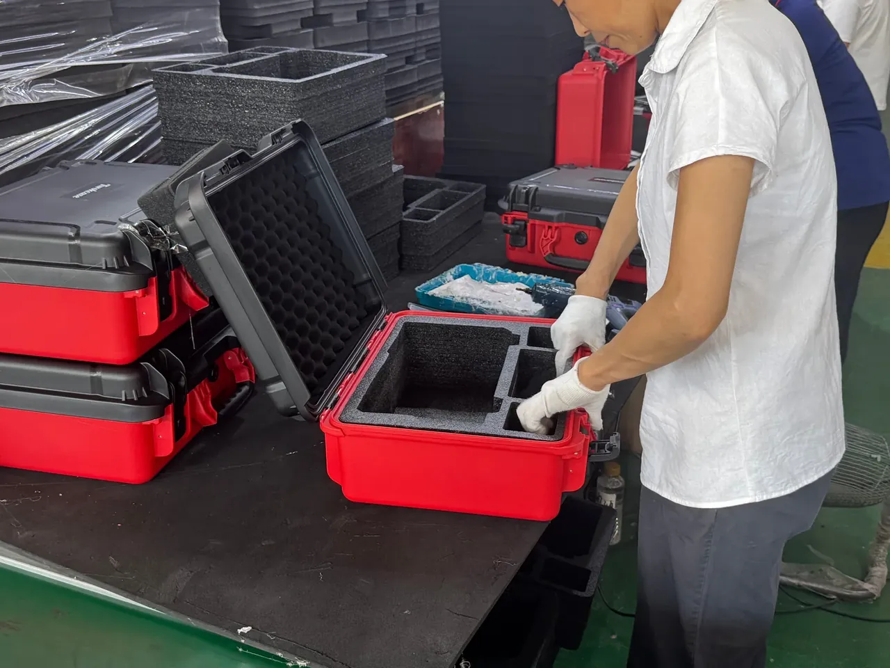
Quick answer: A teach pendant case keeps an 8 inch screen floating 3 mm above 10 mm EPE and coils 7 m of cable on a 220 mm drum, ending at 5.5 kg.
Table of contents
- Four Posts Under the Screen, Not a Flat Press
- Ten Millimetres of EPE and a Three Millimetre Gap
- Coiling Seven Metres on a 220 mm Drum
- The Thirty Millimetre Strain Relief
- One Metre of Drop Against Six Kilos of Carry
- FAQ
1. Four Posts Under the Screen, Not a Flat Press
An 8 inch pendant is 203 mm on the diagonal, 28 mm thick, 1.4 kg, with its glass 2 mm behind the front shell. The first decision is which part carries the screen, not which foam to buy.
Clamping the whole face looks secure and does the opposite: a lid pressing at 0.1 MPa passes every impact into the glass. Four point support sends the load into the bezel corners instead.
The posts are 16 mm across and 10 mm tall, holding the foam 3 mm clear. That 3 mm is calculated, because a 3.0 mm lid sags 1.2 mm at its centre on a 1.0 m drop.
Floating a screen turns a load path into four small contacts.
The foam bears on a 12 mm bezel ring, where 0.1 MPa keeps indentation under 0.2 mm, and the window is cut 1.5 mm oversize per side. Two posts above and two below, 180 mm across and 120 mm vertically, miss the ribbon, which folds at 8 mm radius in a 6 mm relief slot.
| Screen zone | What the case does | Dimension | Check |
|---|---|---|---|
| Display area | Fully floating | 3 mm gap | No foam contact |
| Bezel corners | Four posts | 16 mm x 10 mm | Indentation 0.2 mm max |
| Bezel ring | Foam bearing face | 12 mm | Display left clear |
| Screen ribbon | Relief slot | 6 mm deep | Bend radius 8 mm min |
2. Ten Millimetres of EPE and a Three Millimetre Gap
The lid liner is 10 mm EPE at 30 kg/m³: travel, not filler. The foam absorbs best at 30 percent compression, and 10 mm squeezed by 3 mm sits on that figure.
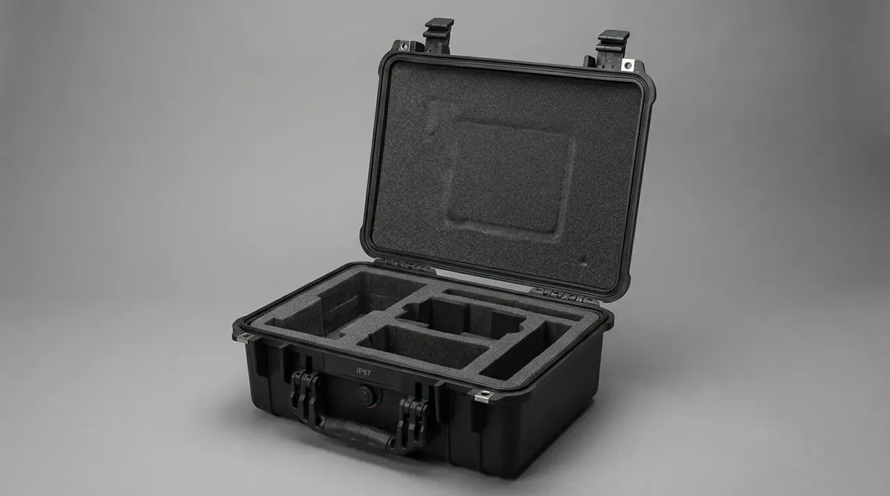
Open the gap to 5 mm and the unit accelerates across the pocket before meeting foam, so the hit lands harder; at 2 mm, assembly preloads the screen.
Cold tightens it further: after 4 h at -20 C the liner compresses 22 percent instead of 30, so 3 mm is all the travel left.
At low temperature the gap is no longer clearance but the last spring in the system.
Three adhesive strips hold the liner on a corona treated face, where peel strength falls from 8 N/25mm to 5 N/25mm in the cold.
3. Coiling Seven Metres on a 220 mm Drum
Seven metres of 11 mm cable is the hardest item to place: pushed in loose, it forms five or more bends under 40 mm radius and the solder joints fail first.
The drum is 220 mm, so one turn is 691 mm and five turns per layer 3.46 m; two layers give 6.91 m with 90 mm left for the exit. Stack height is 11 mm times two plus 2 mm tolerance, 24 mm.
Bend radius is five times the outside diameter, 55 mm, so a 110 mm coil carries a factor of two. Below -10 C the jacket stiffens and at three times diameter the copper yields, with core breaks above 3 percent after 500 flexes; at five times the same cable runs 2000. Wind with the lay of the jacket, or the shield ruckles and an impedance step follows after 300 flexes.
| Coil layer | Turns | Length per layer | Stack height |
|---|---|---|---|
| First, on the drum | 5 | 3.46 m | 11 mm |
| Second, over the first | 5 | 3.46 m | 22 mm |
| Exit transition | Under 1 | 90 mm | 22 mm |
| Tolerance | none | none | 24 mm |
At 0.15 kg/m the cable weighs 1.05 kg, and coiling it to one side puts the centre of gravity 20 mm off centre.
4. The Thirty Millimetre Strain Relief
The 30 mm at the exit is the strain relief length. The cable crosses the wall there, so a 30 mm braid sleeve grips that section and spreads the pull before the solder joints see it.
Two stainless ties 15 mm apart clamp the sleeve over 1 mm silicone tape; an indentation deeper than 0.3 mm halves the flex life.
Pull is checked at 50 N for 1 min with plug movement under 0.5 mm, roughly one hard tug by hand.
Thirty millimetres is the shortest length over which a tug can still be spread out.
The exit flares at R5 with no sharp edge, since a sharp edge cuts a 0.2 mm groove where the core breaks weeks later. The plug has its own bay of 60 mm by 40 mm by 30 mm with 2 mm clearance.
5. One Metre of Drop Against Six Kilos of Carry
A 1.0 m drop on six faces is the standard acceptance item. Peak acceleration at contact is taken as 250 g, and the 10 mm liner with the 3 mm gap brings 45 g to the bezel, where stress stays under 12 MPa.
Weight pulls the other way: empty case 2.4 kg, pendant 1.4 kg, cable 1.05 kg, liner and hardware 0.65 kg, or 5.5 kg against a 6 kg ceiling. Carrying 6 kg for 100 m costs about 15 percent of grip strength.
A 3.5 mm wall adds 0.2 kg and cuts centre sag from 1.2 mm to 0.9 mm, widening the gap margin, and the choice depends on which the customer values more.
Stacking is rated at 3 high, so the bottom lid carries 11 kg of static load rather than impact.
| Drop attitude | Height | Check | Limit |
|---|---|---|---|
| Bottom face | 1.0 m | Bezel displacement | 0.3 mm max |
| Lid face | 1.0 m | Centre sag | 1.2 mm max |
| Edge | 1.0 m | Latch release | Not allowed |
| Corner | 1.0 m | Hinge cracking | Not allowed |
Conclusion
A teach pendant case is decided by two number sets: 3 mm of gap, 10 mm of EPE and 12 mm of bezel move the load off the display, while a 220 mm double coil, 30 mm of strain relief and a 50 N pull check stop the cable load at the wall. The 1.0 m drop and the 5.5 kg carry keep both sets honest, and each 0.5 mm of wall thickness trades one against the other.
This article covers only the case side, meaning the enclosure specifications and what they imply in design. It does not deal with handling, loading or use of anything placed inside.
Related Reading
- How to pack a cobot pendant with its control box
- Fixing robot joint modules inside a case
- Shipping sheet metal for control cabinets
- Transport attitudes for a complete cobot
Related Products
- 8 Series — Gun Cases; Military Equipment Cases; Camera Equipment Cases; Drone Cases; Watch Cases; Knife Cases; First Aid Cases; Electronics Equipment Cases
- WL8-2812 PP Gun Case — model WL8-2812
- All protective cases and toolboxes: 7 series, 158 models