

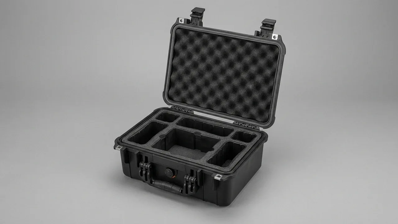
A teach pendant case solves a problem the industry has long underestimated: a pendant is not a general-purpose handheld terminal, but a safety-related device that combines a touchscreen, an emergency stop circuit, an enabling switch and a fieldbus interface in one housing. When it fails, the entire collaborative workstation stops. The core conclusion: transport protection for collaborative robot spares must satisfy three requirements at the same time, namely a static dissipative system built around the IEC 61340 framework, relief-based retention geometry for the screen and the protruding operator controls, and a low-shedding, wipeable design suitable for cleanrooms. A case that only answers the question of drop resistance will fall short on all three.
Every collaborative robot shipment an integrator sends to a customer site typically contains one or more pendants, several controller extension modules, end effectors and grippers of different models, and coiled pendant and drag-chain cable runs. These items travel mixed on a single pallet, absorbing parcel-sorting drops, long-haul vehicle vibration, and repeated manual handling. At the destination, which may be an automotive electronics line, a semiconductor back-end facility, a medical device plant or a food packaging cell, a further gate applies: cardboard fragments, open-cell foam debris and label adhesive residue are all rejected by cleanroom procedures. This article works through the equipment category by category, states protection priorities, and sets out parameters and acceptance practices that can be written straight into a specification.
Table of Contents
- Why Collaborative Robot Spares Are Harder to Protect Than Ordinary Industrial Parts
- Packing List and Vulnerability Analysis by Component
- The Static Dissipative System: Case and Insert Design in the IEC 61340 Context
- The Teach Pendant Itself: Relief-Based Retention for Screens, E-Stops and Enabling Switches
- Pendant Cables and Connectors: Bend Radius and Connector Protection
- Controller Modules: Vibration-Safe Mounting for Power, I/O and Safety Modules
- End Effectors and Grippers: Electric, Pneumatic and Vacuum Compared
- Cleanroom Compatibility: Low Shedding, Wipeability and Low Outgassing
- Modular Insert Design: Model Matching and Fast Changeover
- Case Shell and Hardware Selection
- Environmental Testing and Compliance References
- Specification Parameters to Lock Down Before Ordering
- OEM/ODM Programmes and Batch Consistency Control
- Frequently Asked Questions
- Conclusion and Further Reading
Why Collaborative Robot Spares Are Harder to Protect Than Ordinary Industrial Parts
A conventional spare parts case tends to serve a narrow situation: one model number, high quantity, interchangeable units. Collaborative robot spares present the opposite profile. Model numbers are scattered, quantities are small, unit value is high, and most items carry a safety function. Those four traits set the direction of the design.
First, the pendant is a safety device, not a consumer electronic. Its emergency stop circuit, three-position enabling switch and safety fieldbus interface all belong to a safety-related chain. If impact during transport changes the travel of a switch or produces micro-movement at the contacts, the unit may behave intermittently once returned to service, and tracing that behaviour is extremely costly. For safety-related parts, appearance-based acceptance criteria are simply not adequate.
Second, the controller arrives disassembled. To reduce packed height and allow staged delivery, power supplies, I/O modules, safety modules and drive modules are frequently removed from the DIN rail and packed individually. Once removed, a module loses the mechanical restraint of the rail and cabinet, which makes it more vulnerable in transit than a complete cabinet, particularly for a power supply carrying heatsinks and electrolytic capacitors.
Third, end effectors vary enormously in form. Three units all called a gripper can be an electric parallel gripper containing a screw drive or a harmonic reducer, a pneumatic gripper built around seals and threaded air ports, or a vacuum cup assembly made of elastomer. Each is sensitive to impact, pressure and storage conditions along a different axis, so one insert logic cannot serve all three.
Fourth, the destination is often a cleanroom. Collaborative robot cells in automotive electronics, semiconductor back-end, pharmaceutical and food plants commonly sit inside an area classified under the ISO 14644 series. A packaging material that sheds particles, contains silicone, or releases condensable volatiles will contaminate the environment the moment the case is opened, and can affect yield. Baseline material and sealing considerations are covered in seal material selection and compatibility.
The difference in one sentence: a conventional spares case answers whether the contents will break, while a collaborative robot case must also answer whether it will carry static charge, whether it will contaminate a cleanroom, and whether it will allow a safety function to drift unnoticed.
Packing List and Vulnerability Analysis by Component
A complete list is the prerequisite for insert zoning. The table below covers the main items in a typical collaborative robot delivery package.
| Component | Typical specification and mass | Primary vulnerability | Protection priority |
|---|---|---|---|
| --- | --- | --- | --- |
| Handheld teach pendant | 8 to 12 inch screen, 1 to 2 kg | Touchscreen cracked under pressure, E-stop mushroom compressed, enabling switch travel altered | Highest |
| Tablet-style pendant | 10 to 13 inch screen, 1.5 to 3 kg | Screen corner chipping, housing distortion, keypad binding | Highest |
| Controller power supply module | DIN rail unit, 0.8 to 3 kg | Electrolytic capacitors shock loaded, heatsink deformed, fan blades broken | High |
| I/O and communication modules | DIN rail unit, 0.3 to 1 kg | Terminal blocks stressed, board components dislodged, ESD | High |
| Safety module | DIN rail unit, 0.3 to 1 kg | Latent ESD damage, dual-channel contacts micro-moved | High |
| Six-axis force and torque sensor | Flanged body, 0.5 to 3 kg | Strain body micro-deformation, calibration curve shifted | Highest |
| Electric gripper | 0.5 to 4 kg | Screw drive and reducer axially shock loaded, finger seating surface damaged | High |
| Pneumatic gripper | 0.4 to 3 kg | Air port threads bruised, seals permanently flattened | High |
| Vacuum cup assembly | 0.2 to 2 kg | Rubber lip permanently compressed, oil and dust contamination | Medium-high |
| Replaceable fingers and tooling blocks | 0.05 to 0.5 kg | Thin-wall deformation, paired items lost or mismatched | Medium |
| Pendant cable | 3 to 10 m, 2 to 6 kg | Bend radius too small, shield fatigue, connector pins deformed | High |
| Vision and camera modules | 0.3 to 2 kg | Lens surface contamination, optical axis shifted by shock | High |
| Spares kit | Encoder batteries, fuses, seals | Battery leakage, small parts lost | Medium |
How the priority ranking is decided. The highest priority items share one property: their calibrated state is not recoverable in the field. Once a mechanical zero point drifts after an impact, the unit must go back to the factory for recalibration. Force and torque sensors and pendants both fall into this group. High priority items are those where partial failure stops the whole machine, such as a safety module or a servo drive module. Medium priority items can be replaced on site, so the protection objective is simply to prevent cracking and loss.
A detail that is easy to miss: pendants and end effectors are usually shipped as matched pairs and returned for repair as pairs. If the insert is designed for single units only, integrators end up mixing pendants from different models during fitting, and the pairing can no longer be traced at repair time. Reserve a writable identification area beside each slot and supply a slot manifest card with the case. The full customisation route is described in EVA foam insert customisation process.
The Static Dissipative System: Case and Insert Design in the IEC 61340 Context
Collaborative robot cells appear on electronics assembly lines in large numbers, and pendants and end effectors are touched by human hands throughout assembly, commissioning and maintenance. The whole packaging stage therefore belongs inside the static control programme.
The resistance band is the first decision. Under the common classification used in IEC 61340-5-1 and ANSI/ESD S541, a surface resistance below 10⁴ ohm is conductive, between 10⁴ and 10⁹ ohm is static dissipative, and above 10¹¹ ohm is insulative. Insert material that touches the equipment should be static dissipative, neither conductive nor insulative. A conductive material discharges too abruptly, and the current spike at the moment of contact can still damage a device. An insulative material accumulates triboelectric charge and then releases it in one event as it approaches a circuit board. These two errors account for most field failures in this category.
Shell options. Three routes, each with trade-offs:
- Conductive polymer shell filled with carbon black or carbon fibre: dissipates as a whole volume and is simple to ground, but colour choice is usually limited to black and the surface resistance shifts with humidity and wear.
- Metal shell built on an aluminium frame with panels: excellent shielding and structural stiffness, well suited to long-distance transport of high-value modules, but heavier and requiring corrosion treatment.
- Standard engineering polymer shell with a dissipative insert: the lowest cost and the most customisable in appearance, and the route most integrators choose, provided both the insert material and its structure are controlled to the dissipative band.
Grounding and shielding. Board-level modules that will be stored for long periods or moved between regions should first go into a metallised shielding bag and then into the slot. The bag provides Faraday shielding while the dissipative insert provides slow bleed-off, and the two functions are not interchangeable. Where a conductive polymer shell is used, provide an explicit grounding point with a grounding stud so the case can be bonded inside an ESD protected area.
Humidity and people. A dry environment dramatically increases static accumulation, so the relative humidity in an ESD protected area is normally kept above 40 percent. In a dry northern winter production hall, even correct packaging material will not prevent a high-voltage discharge if the operator is not wearing a wrist strap. The packaging package should therefore ship with a handling instruction requiring operators to wear a wrist strap and to unpack on a dissipative bench mat.
Where cleanroom and antistatic requirements conflict. Cleanrooms demand low particle shedding, yet some antistatic agents are migrating additives that slowly bloom to the surface and become contamination. The solution is to prefer intrinsically conductive or intrinsically dissipative polymers over surface-coated or additive-migration materials, and to require blooming and outgassing data from the material supplier at the purchasing stage. See ESD-shielded case and insert design for the design approach.
The Teach Pendant Itself: Relief-Based Retention for Screens, E-Stops and Enabling Switches
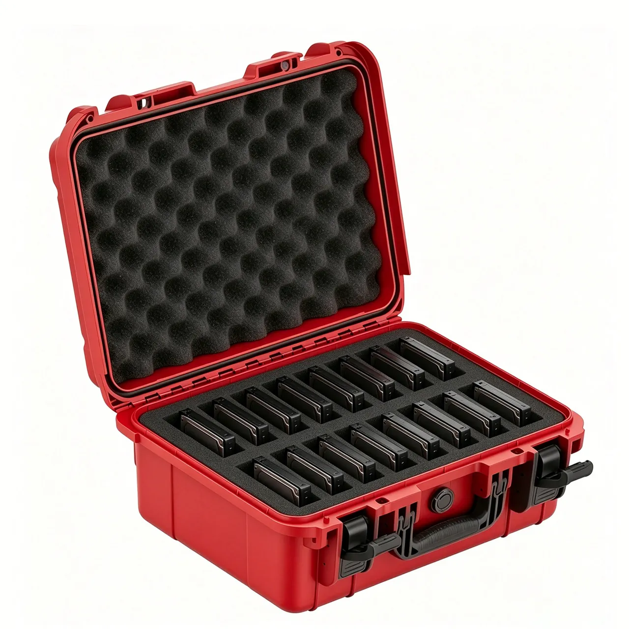
The pendant is the only item in the case that is both precision equipment and a frequently handheld tool, and it carries more protruding features than anything else. Retention logic must follow a fixed order: relief first, support second, clamping last.
The touchscreen. A screen is a laminated assembly in which the cover glass and the display module are bonded with optical adhesive, and face pressure produces local discolouration or touch drift. The pendant housing frame should carry the load, with 8 to 10 mm of clearance left between the screen face and the insert. Where the unit is carried face-down in a cavity, a rigid support plate is required above the screen; soft foam pressed directly onto the glass is never acceptable. A factory-applied screen protector does not substitute for structural relief.
The emergency stop button. A red mushroom head typically stands 10 to 15 mm proud of the shell, making it the most prominent feature on the unit. If the pendant lies flat in the conventional way, the entire weight rests on the E-stop and can alter its travel or hold its normally closed contacts open. Carve a relief bore matched to the button diameter with a depth of at least 1.5 times the button height, so the button hangs completely free.
The three-position enabling switch. Located on the grip side, the enabling switch has three defined positions and an internal spring and contact travel that is highly sensitive. The insert must be fully relieved at this location with no compressive feature of any kind, and the side carrying the switch should not face downwards.
Knobs and toggle switches. Mode selector knobs and speed override wheels are small protruding parts that an insert edge can shear. Provide an annular relief cavity with at least 2 mm of clearance around the knob circumference.
Grip and centre of gravity. An insert that requires significant force to extract the pendant is a design error. Provide two finger channels or a pull strap at the base of the pendant slot so the unit is lifted rather than prised out, and keep the pendant out of the same layer as heavy items to prevent accidental contact during unpacking.
Temperature and storage. A liquid crystal display responds slowly and loses contrast when cold, while prolonged high-temperature storage can accelerate polariser ageing. Transport packaging should prevent long periods of direct sun exposure that drive internal temperatures up, and the specification should state a storage temperature limit. Wider temperature considerations appear in case design for extreme temperature environments.
Pendant Cables and Connectors: Bend Radius and Connector Protection
Cables are the item most often pushed into whatever space remains, and they are also the leading cause of field failure: most reported pendant communication dropouts trace back to deformed connector pins or a fatigued shield.
Bend radius. A pendant cable is a multi-conductor shielded assembly. For static storage, the minimum bend radius should be four to five times the cable outer diameter; for dynamic drag duty it needs six to ten times. For a typical 9 mm pendant cable, the static coil diameter should be no less than 80 mm, and in practice coiling to a diameter above 300 mm is recommended, secured with hook-and-loop tape. Never cinch a cable with a cable tie. A tie flattens the local cross-section and destroys the concentricity of the shield and insulation layers.
Coiling method. Use same-direction overlapping coils or a figure-of-eight alternation rather than repeated twisting. Twisting introduces torsional stress into the braided shield, which relaxes into a springy coil in storage and forms hard knots when the cable is deployed. The figure-of-eight method is particularly suitable for cables that are unfurled frequently.
Connector protection. The dedicated multi-pin connector at the pendant end and the circular connector at the controller end are both precision interfaces and must carry protective caps or dust plugs in transit. Caps should be tethered to the cable with a flexible leash so they are not lost on site. A connector must never be a load-bearing point: a coiled cable should not be hung from its plug.
Drag-chain cable and pneumatic tubing. High-flex drag-chain cable is designed to resist bending, not torsion. Once twisted in transit, its stranded construction takes a permanent set. Coil it separately and give it a dedicated trough or fabric sleeve inside the case. Polyurethane tubing for pneumatic grippers is easily kinked; control the minimum bend radius at five times the outer diameter, fit protective sleeves over push-in fittings, and keep them free of lateral load.
Where cables should live. Route the cable trough along the inner wall of the case rather than across the central cavity. This preserves a flat bearing surface for precision items and prevents cables from being pinched when the lid closes. Where a cable run exceeds 5 metres, use a separate long accessory bag hung on the outside of the case instead of forcing it inside.
Controller Modules: Vibration-Safe Mounting for Power, I/O and Safety Modules
Once modules are removed from the DIN rail they lose the restraint provided by the cabinet, and vibration protection has to be rebuilt from scratch.
Power supply modules. These contain relatively heavy electrolytic capacitors and inductors, which amounts to heavy elements suspended inside a light housing and makes them especially sensitive to high-frequency vibration. Fit silicone damper pads at all four corners and seat the module in a matched EVA slot to create two-stage isolation. Thick foam used as single-stage cushioning compresses to its dense state under high acceleration, at which point isolation disappears and shock transfers straight through to the housing and the internal components. This is the most common design mistake in this category.
Heatsinks and fans. A module with cooling fins is easily flattened by compression in transit, and a module with a fan contains thin blades that break readily once debris enters. Leave a clearance cavity on the heatsink side rather than clamping it, and fit a temporary dust sticker over the fan intake or orient the intake away from the shedding direction.
I/O and communication modules. Terminal blocks are the most protruding feature, and pluggable terminals can work loose under pressure. Pack the module with the terminals facing upwards, or carve relief slots under the terminal block. Board-level modules should go into a shielding bag first, then receive edge corner protectors so that fingers never touch the gold contact fingers during handling.
Safety modules. As safety-related parts, these require protection against shock as well as vibration and ESD. Give them a dedicated cavity, keep them out of the same layer as heavy items, and label the slot with the module model so that mixed installations can still be traced later.
Spares and consumables. Encoder batteries and SSD backup batteries are lithium or alkaline cells that need protection against leakage and short circuits, so they belong in a separate small cavity with insulated terminal caps. Fuses and seals are better held in a compartmented box with generously radiused pocket floors so small parts cannot jam.
Labelling and matching. The controller module case is typically unpacked once and used across several installation points over a period of weeks. Slots should carry replaceable label strips showing the module model and the associated robot serial number, with a slot manifest card inside the lid. This measurably shortens on-site inventory work for integrators.
End Effectors and Grippers: Electric, Pneumatic and Vacuum Compared
End effectors are the most form-diverse category in the package, and "one gripper, one solution" is not an exaggeration.
| Effector type | Mass and construction | Load it tolerates worst | Insert design points | Accessory notes |
|---|---|---|---|---|
| --- | --- | --- | --- | --- |
| Electric parallel gripper | 0.5 to 4 kg, screw drive or harmonic reducer | Axial shock, shear at the mounting base | Base face fully supported, no load along the stroke axis | Fingers packed separately |
| Electric rotary gripper | 0.8 to 4 kg, hollow rotating shaft | Radial shock, shaft bending | Support the shaft at both ends, avoid cantilever | Calibration data travels with the unit |
| Pneumatic gripper | 0.4 to 3 kg, seals and air ports | Thread damage at air ports, seals flattened | Air port relief cavities, body positively located | Protective sleeves on push-in fittings |
| Vacuum cup assembly | 0.2 to 2 kg, rubber lip | Permanent lip compression, oil and dust contamination | Cups suspended, load carried by the mounting stem only | Spare cups stored separately |
| Magnetic gripper | 1 to 8 kg, permanent magnets | Adhesion of ferrous debris, demagnetisation on impact | Dedicated cavity, kept away from ferrous parts | Magnetic isolation liner |
| Six-axis force and torque sensor | 0.5 to 3 kg, strain body | Any face contact pressure, bending moment | Flange face carries load, strain body fully suspended | Calibration certificate travels with the unit |
| Tool changer and flange | 0.3 to 2 kg | Seating face bruised, ball-lock mechanism contaminated | Seating face inwards with a cap fitted | Storage position for the cap |
Three universal rules:
- Anything that must float stays free. The outer rim of a force sensor strain body, the rubber lip of a vacuum cup, and the stroke zone of an electric gripper must all remain clear of contact. Any face pressure causes irreversible calibration drift or elastic deformation.
- Heavy items sink. Magnetic grippers and large tool changers belong at the bottom of the case near the handle, which lowers the overall centre of gravity and prevents tipping during handling.
- Matching parts stay together. Fingers, flanges, pneumatic fittings and calibration certificates should travel in the same slot as their effector with an unambiguous pairing. The communication cost of a missing accessory at repair time often exceeds the value of the case itself.
Electric grippers carry a second risk in static. The servo drive board and encoder inside the gripper are ESD sensitive, and direct contact with foam that has not been treated for dissipation can allow an assembly-line static event to corrupt encoder readings. The resistance bands discussed in the ESD section above apply here as well.
Cleanroom Compatibility: Low Shedding, Wipeability and Low Outgassing
When a collaborative robot is delivered to a semiconductor back-end, pharmaceutical or food packaging line, the packaging itself enters a controlled environment.
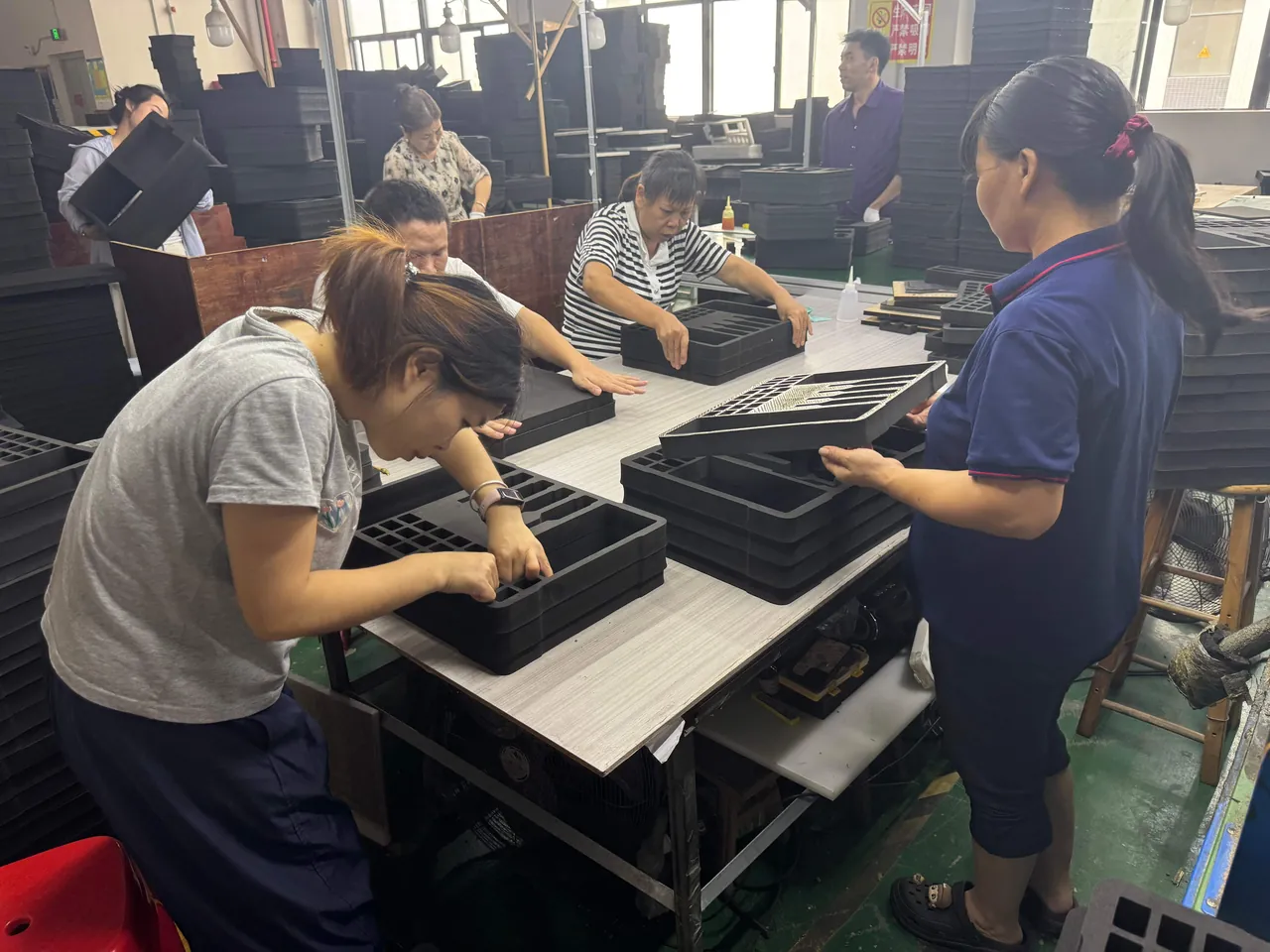
Three material prohibitions. First, no open-cell sponge, because its porous structure releases debris continuously. Second, no corrugated board or kraft paper as insert or void fill, because paper generates fibre dust through friction. Third, no surfaces treated with silicone release agents or silicone lubricants, since silicone contamination is damaging to both paint lines and semiconductor processes.
Recommended insert construction. Use closed-cell EVA or cross-linked PE as the structural material, laminated on the outer face with a dense wipeable textile or nonwoven. The surface textile must simultaneously meet low-shedding and antistatic requirements, and must withstand wiping with isopropyl alcohol or ethanol without colour transfer or fibre lift.
Case exterior. Cases get carried into clean areas, so exterior surfaces should be smooth and untextured, avoiding grooves and knurling so they can be wiped quickly with a lint-free cloth. Avoid deep channels on the underside where dust collects. Where a trolley handle and wheels cannot be fully cleaned, switch to a wheel-free carrying case before entering the clean zone.
The double-packaging strategy. The accepted practice is an outer transport case plus an inner cleanroom bag: the equipment is bagged and heat sealed under clean conditions, then placed in the transport case. On entering the clean zone, the outer case is removed in the airlock and only the bag goes through. This decouples transport protection from cleanroom protection, letting the outer case be designed for mechanical performance without compromising structure for cleanliness.
Low outgassing. Where equipment will be stored long term inside a clean area, for example a spare pendant hanging beside the workstation, the condensable volatile specification of the packaging material becomes relevant. The usual evaluation follows the total mass loss and collected volatile condensable materials metrics associated with the ASTM E595 context, and suppliers can be asked for a material declaration. Plasticised flexible PVC components should be avoided entirely.
Labelling. Ordinary paper labels are unsuitable inside clean zones because both the paper and the adhesive shed. Use low-particle labels or laser marking directly on the shell, supplemented by replaceable slot identification strips.
An outcome-based check. The simplest validation of cleanroom suitability is to wipe the case interior and insert surfaces with a lint-free cloth immediately after opening and inspect the cloth for visible particles. That single action gets closer to real performance than any paper declaration. Cleanroom classification requirements are set out in the ISO 14644 series.
Modular Insert Design: Model Matching and Fast Changeover
Collaborative robots iterate quickly and multiple models coexist, so a pendant specified today may be replaced within two or three years, and grippers are almost always built to the station. An insert carved as a single dedicated block means scrapping the whole tool when the model changes.
Three modular insert structures:
- Removable divider type. The insert is built from a set of cross-cards and dividers, and slot dimensions are set by divider position. This suits regular-shaped controller modules and spares; adjustment is flexible but retention precision is lower.
- Zoned module type. Split the interior into three independent modules for pendant, controller modules and effectors, each carved and replaceable on its own. A model change replaces one module while the shell and remaining modules stay in service.
- Inserted locator type. Reserve standardised locator grooves in the main insert and adapt them to similar-sized items with locator blades of different thickness, which suits grippers and flanges in multiple sizes.
Three critical pendant dimensions. Whatever structure is chosen, the pendant slot must be dimensioned against three measured values: the widest point of the grip section, the total thickness from screen face to the highest point at the back, and the stand-off height of the E-stop on the shell. Across manufacturers and generations these three values can vary by 10 to 20 mm, while published specification sheets usually state only the screen size.
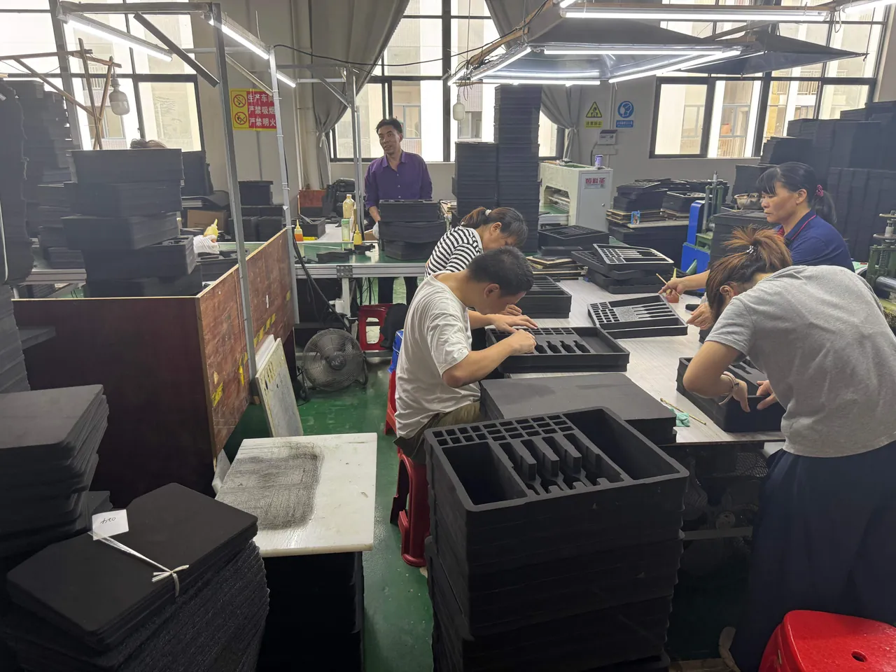
An engineering approach to fast changeover. Express the insert drawing as a datum plus adjustable parameters: use the inner wall of the case as the datum, annotate slot-critical dimensions as variables, and attach a model cross-reference table. Adding a new model then means updating parameters rather than redesigning the whole case. Integrators representing several brands can ship as one shell with multiple inserts matched to each project, which prevents the number of shell variants from multiplying.
Retrieval order and inventory. Put the pendant in the upper layer, since it is handled most often and is moderate in weight; controller modules in the middle; effectors and heavy items at the bottom. A slot cross-reference card inside the lid, or a case lid with a viewing window, allows inventory to be checked without opening. Where zoning changes frequently, a removable divider system is a more flexible intermediate option than a fully carved insert.
Case Shell and Hardware Selection
The shell sets the frame, and what it determines is long-term serviceability. Collaborative robot spares cases are opened and closed more often than general industrial spares cases, so hardware life should be specified as a separate requirement.
Hinges. Choose stainless steel pins in a recessed design so the lid stays within the case profile at 180 degrees of opening, which reduces transport loading. The hinge seat needs its own relief groove so the main gasket is not pinched near the hinge and cannot form a water path. Hinges are the first component to develop play, so cycle test results for open-close life are a reasonable purchasing requirement.
Latches. Integrator shipments often pause at a transit warehouse, so latches need an anti-accidental-release feature. A dual-action press-to-release latch requires two distinct movements and resists vibration-induced opening. Where a customer padlock or a tamper seal must be fitted, choose latches with a lock aperture; the available variants are described in case lock customisation options.
Sealing and ingress protection. Most collaborative robot spares travel indoors, where IP54 to IP56 usually satisfies dust and splash requirements. Move to IP67 where sea freight, open-vehicle transfer or wet wiping in a clean zone is involved. Gasket compound must balance wipe resistance against low shedding; silicone and EPDM are both workable, but confirm that the surface will not release siloxanes into a clean environment. Hardware and gasket interaction is covered in toolbox hinges, latches and sealing structure.
Handles and handling. A case holding a pendant plus controller modules typically weighs between 15 and 30 kg loaded. The handle should be rated for twice the loaded mass with metal reinforcement designed into the mould. Above 30 kg, add castors and a telescopic trolley handle, while retaining a top handle for short lifts. Wheel and handle configurations are described in case wheels and trolley handle design.
Stacking and corner reinforcement. Integrator warehouses and production floors stack cases routinely. The four corners concentrate stacking load, so thicken them in the mould or add reinforcing ribs. State the permitted stacking height and load in the specification so that unlimited stacking on site cannot bulge the lower case walls.
Environmental Testing and Compliance References
Validation items should match the actual logistics chain rather than following a standard template.
| Verification item | Common reference | Parameter basis for collaborative robots | What to watch |
|---|---|---|---|
| --- | --- | --- | --- |
| Dust and water ingress | IEC 60529 | IP54 to IP56 indoors, IP67 for sea freight or wet wiping | Gasket wipe resistance and recovery |
| Drop | ISTA series, ASTM D4169 | Drop sequence covering corner, edge and face | Hinge seats, latch seats, four corners |
| Vibration | GB/T 4857 series | Simulating long-haul road transport and parcel sorting | Slot wear, fastener loosening |
| Stacking | GB/T 4857 stacking clauses | 24 hours at rated load | Sidewall bulge, corner deformation |
| Static dissipation | IEC 61340-5-1 framework | Surface resistance of inserts between 10⁴ and 10⁹ ohm | Consistency of equipment contact surfaces |
| Cleanliness | ISO 14644 series | Matched to the destination cleanroom class | Insert shedding, exterior wipeability |
| Condensable volatiles | ASTM E595 context | Set by long-term cleanroom storage requirements | Insert adhesives and textiles |
| Salt fog | GB/T 10125 | Sea freight or coastal storage | Hinges, latches, screws |
| Environmental test methods | MIL-STD-810H, method reference | Used to set drop heights and vibration spectra | Statement must note it is not a military certification |
One point on the last row deserves repetition: citing MIL-STD-810H as an environmental test method reference in a specification is professional practice, but it must never be written as certification. Accurate wording clearly distinguishes method reference from certification, and the phrasing that survives procurement review is set out in MIL-STD-810H and case environmental testing. Sequential transport validation is described in ISTA transport testing procedure.
Specification Parameters to Lock Down Before Ordering
The parameters below should be written into the specification line by line, providing a shared basis for design review and acceptance.
| No. | Parameter | Suggested wording |
|---|---|---|
| --- | --- | --- |
| 1 | Ingress protection | IP54 to IP56 indoors; IP67 for sea freight or cleanroom wet wiping |
| 2 | Shell material | Copolymer polypropylene or conductive filled engineering polymer, with target surface resistance stated |
| 3 | Static dissipation | Insert surface resistance 10⁴ to 10⁹ ohm per the IEC 61340-5-1 framework |
| 4 | Insert structure | Zoned modular construction with zoning drawing and replaceable module list |
| 5 | Pendant slot | State grip width, overall thickness and E-stop relief depth |
| 6 | Screen protection | Clearance between screen face and insert of at least 8 mm, no face pressure |
| 7 | Cable storage | Dedicated trough, static bend radius at least 4 times the outer diameter |
| 8 | Cleanroom suitability | Closed-cell materials, no open-cell sponge or paper fill, wipeable exterior |
| 9 | Low outgassing | Material declaration per the ASTM E595 context where long-term cleanroom storage applies |
| 10 | Hardware | Stainless steel hinges, dual-action latches, optional lock aperture |
| 11 | Handling features | Handle rated at twice the loaded mass; castors and trolley above 30 kg |
| 12 | Marking and documents | Slot manifest card, low-particle labels, compartmented spares box |
| 13 | Acceptance rules | Sampling plan with defect classification, including a physical fit trial |
Items five and thirteen are the clauses most often simplified away, and they are also the two with the highest rework cost. Sampling logic and defect grading are described in custom case acceptance and AQL sampling.
OEM/ODM Programmes and Batch Consistency Control
Purchasing rhythms in the collaborative robot industry differ from those of meteorological or energy projects: models iterate quickly, batch quantities are small, and delivery windows are short. Suppliers therefore need fast prototyping and flexible scheduling.
First articles and physical fit. Every time a new model is introduced, a physical trial assembly with the real unit is essential, focusing on E-stop relief depth, screen clearance and cable trough width. Drawing checks with calipers are insufficient because pendant housings are mostly curved transitions, and paper dimensions cannot represent real seating behaviour.
Insert consistency. The main risk with carved inserts is slot dimension drift between batches. EVA shrinks 2 to 5 percent after repeated compression, so drawings should carry slot tolerances and compensation allowances, and critical slot dimensions should be sampled per batch rather than relying on visual inspection.
Static material consistency. Surface resistance of dissipative materials is sensitive to humidity and to batch, and values between batches of the same specification can span half an order of magnitude. Sample surface resistance per batch of insert material and keep the records, so that if a customer reports a static event there is traceable evidence.
Change control for cleanroom materials. Where equipment is delivered into a cleanroom, the insert surface textile, adhesives and labels are all items under change control. A supplier should notify the customer before switching any contact material source and should reissue shedding and outgassing data.
Supply and service scope. A capable supplier should offer inserts customised to pendant and gripper models, OEM/ODM appearance and structural design, seals and hardware matched to the models, material declarations and test reports shipped with the goods, and separate supply of consumables such as gaskets, desiccant, protective caps and hook-and-loop ties. The JUNZHIJIA brand, manufactured in Guangdong, can produce drawings with tolerances item by item against pendant and effector model lists. A complete evaluation framework appears in how to choose a protective case OEM factory.
Frequently Asked Questions
Q: Why can't a teach pendant simply be wrapped in foam like a tablet computer?
A: Because a pendant differs from a consumer device in both geometry and safety role. Its emergency stop button typically stands 10 to 15 mm proud of the shell, and the enabling switch sits on the grip side with a precision spring and contacts inside. Any wrap that compresses the whole unit transfers its full weight onto those two features, altering button travel or holding contacts closed, so the pendant may trigger intermittently once returned to service and tracing that behaviour is very expensive. Soft foam alone does not solve the problem either, because under high acceleration it compresses to its dense state and stops isolating. The correct approach is to let the pendant housing frame carry the load, carve an E-stop relief bore at least 1.5 times the button height, fully relieve the enabling switch side with the switch not facing down, and leave 8 to 10 mm of clearance between the screen face and the insert.
Q: Does a collaborative robot spares case really need static control, and which items need it most?
A: Where the destination involves electronics assembly, test or cleanroom operations, the whole package should be brought inside the static control programme, because packaging is the one link in the static chain a supplier can fully control. Ranked by urgency, the items needing it most are the controller safety module and I/O modules, the servo drive board and encoder inside an electric gripper, vision and camera modules, and the pendant itself. The test is not whether an exposed circuit board is visible but whether the device is sensitive to electrostatic discharge. Many modules have fully enclosed metal housings while their terminal blocks and pins still connect directly to internal devices. Under the classification commonly used in IEC 61340-5-1, insert material in contact with equipment should be static dissipative, with a surface resistance from 10⁴ to 10⁹ ohm, rather than conductive or insulative. Buyers should also ask what changes if the insert supplier switches material sources, because a nominal specification alone does not guarantee the same electrical behaviour across deliveries.
Q: Why is conductive material unsuitable for direct contact with pendants and grippers?
A: Conductive material has a surface resistance below 10⁴ ohm, so charge bleeds off extremely fast and the moment of contact produces a relatively high current spike. For a device that already carries static charge, that rapid discharge can itself cause damage, in much the same way as touching a circuit board with a bare hand. Static dissipative material stretches the discharge event out so charge leaves at a controlled rate, satisfying both the requirement not to accumulate and the requirement not to dump. The correct combination is therefore: a dissipative insert for slow bleed-off at the equipment contact surface, a metallised shielding bag for field shielding of board-level modules, and a grounding point on the shell to conduct accumulated charge to earth. The three functions are distinct and cannot substitute for one another. Insulative foam is the worst option of all, since it neither bleeds nor shields and simply accumulates charge through friction.
Q: How should a pendant cable be coiled so it does not fail in service?
A: Control the bend radius and avoid torsion. A pendant cable is a multi-conductor shielded assembly, so the minimum bend radius for static storage should be four to five times the outer diameter, rising to six to ten times for dynamic drag duty. For a typical 9 mm pendant cable the static coil diameter should be at least 80 mm, and coiling to a diameter above 300 mm secured with hook-and-loop tape is the practical recommendation. Use same-direction overlapping coils or a figure-of-eight alternation rather than repeated twisting, because twisting introduces torsional stress into the braided shield that relaxes into a springy coil during storage and knots during deployment. Cable ties must not be cinched tight, since they flatten the local cross-section and destroy concentricity. A connector must never carry load, so a coiled cable should not hang from its plug. Where several pendants travel together, give each cable its own trough position rather than piling them into one void.
Q: What are the most common cleanroom violations in collaborative robot packaging?
A: The three most frequent are open-cell sponge, paper-based materials and silicone-treated surfaces. Open-cell sponge releases debris continuously through the friction of loading and unloading, corrugated board and kraft paper generate fibre dust, and surfaces treated with silicone release agents or lubricants release siloxanes into the clean environment, which affects paint lines and semiconductor processes directly. Ordinary paper labels shed from both the paper and the adhesive as well. The correct approach is closed-cell EVA or cross-linked PE for the insert with a wipeable dense textile on the outer face, smooth untextured exterior surfaces for fast lint-free wiping, and low-particle labels or laser marking instead of paper. Where equipment is stored long term inside a clean zone, condensable volatile data per the ASTM E595 context should also be requested. A practical acceptance step is to wipe the insert immediately after opening and inspect the cloth for visible particles. Where a case is reused for several deliveries, replace the surface textile when it becomes glossy or begins to lift at the edges.
Q: If the insert is carved as one dedicated block, what happens when the robot model changes?
A: A fully carved insert generally has to be remade entirely when the model changes, so tooling and sampling costs recur each time. A zoned modular structure is preferable. Split the interior into three independent modules for the pendant, the controller modules and the effectors, each carved and replaceable on its own, so a model change replaces one module while the shell and the others stay in service. Similar-sized grippers and flanges can be accommodated by reserving standardised locator grooves in the main insert and adapting them with locator blades of different thickness. Express the drawing as a datum plus adjustable parameters, using the case inner wall as the datum and annotating slot-critical dimensions as variables with a model cross-reference table attached, so a new model only requires updating parameters rather than redesigning the full case. Integrators who handle several brands should also keep one shell family and order inserts per project, which prevents the number of shell variants from growing out of control over a few years.
Q: Does a collaborative robot spares case need to reach IP67?
A: It depends on the logistics chain and the delivery environment, and most indoor scenarios do not require it. Integration, commissioning and maintenance for collaborative robots happen inside production buildings, and transport is usually by box truck and pallet sorting, so IP54 to IP56 dust and splash protection is generally sufficient. Three situations justify moving to IP67: sea freight or open-vehicle transfer, a destination where the case must be wet wiped to satisfy cleanroom requirements, and storage conditions that are damp or prone to condensation. Note that a higher sealing class usually means greater closing force and faster gasket wear, and collaborative robot spares cases are opened far more often than general industrial cases, so chasing the highest rating can actually shorten gasket life. A pragmatic middle path is an IP54 outer case combined with an inner cleanroom bag, which decouples the two protection problems. Whatever class is chosen, make the gasket a replaceable item and put it on the annual replacement list.
Q: What usually goes wrong when controller modules are packed off the DIN rail?
A: Problems concentrate in three areas. The first is failed vibration isolation: a power supply contains relatively heavy electrolytic capacitors and inductors, effectively heavy elements suspended inside a light housing, so single-stage thick foam compresses to its dense state under high acceleration and transfers vibration directly into capacitor leads. The second is damage to protruding features, since terminal blocks, cooling fins and fan blades all project beyond the housing and deform or break under pressure, which is why modules should be packed with terminals facing up or in a carved relief slot. The third is static and mixing, because a safety module is a safety-related part that should have its own cavity separate from ordinary I/O modules, should avoid sharing a layer with heavy items, and should carry a model label at the slot so mixed installations remain traceable. Insist on a physical fit trial for each module type rather than accepting drawing checks alone.
Q: What documents and supply capabilities should a supplier provide for a batch order?
A: Settle both the document set and the supply scope at the quotation stage. Documents should include insert zoning drawings with tolerance tables stating the critical pendant slot dimensions, material declarations covering closed-cell construction, surface resistance sampling records and, for cleanroom use, shedding and outgassing data, hardware specifications and test reports covering hinge cycle life, latch function and salt fog duration, and the sampling plan and defect classification definition to be used at acceptance. On supply, confirm the ability to customise inserts to pendant and gripper models, to support OEM/ODM appearance and structural design, to match seals and hardware to the models, and to supply consumables separately, including gaskets, protective caps, hook-and-loop ties and compartmented spares boxes. Without an independent channel for consumables, on-site maintenance costs rise sharply.
Conclusion and Further Reading
Choosing a teach pendant case is not mainly about building a stronger box. It is about serving three different constraints at once: static dissipation for the long-term reliability of electronics and safety modules, relief-based geometry that preserves the calibrated state of pendants and effectors, and cleanroom compatibility so the package passes the line entrance. Getting the priority ranking, the modular insert and the specification parameters right keeps both rework and on-site adaptation cost low.
Related Reading