

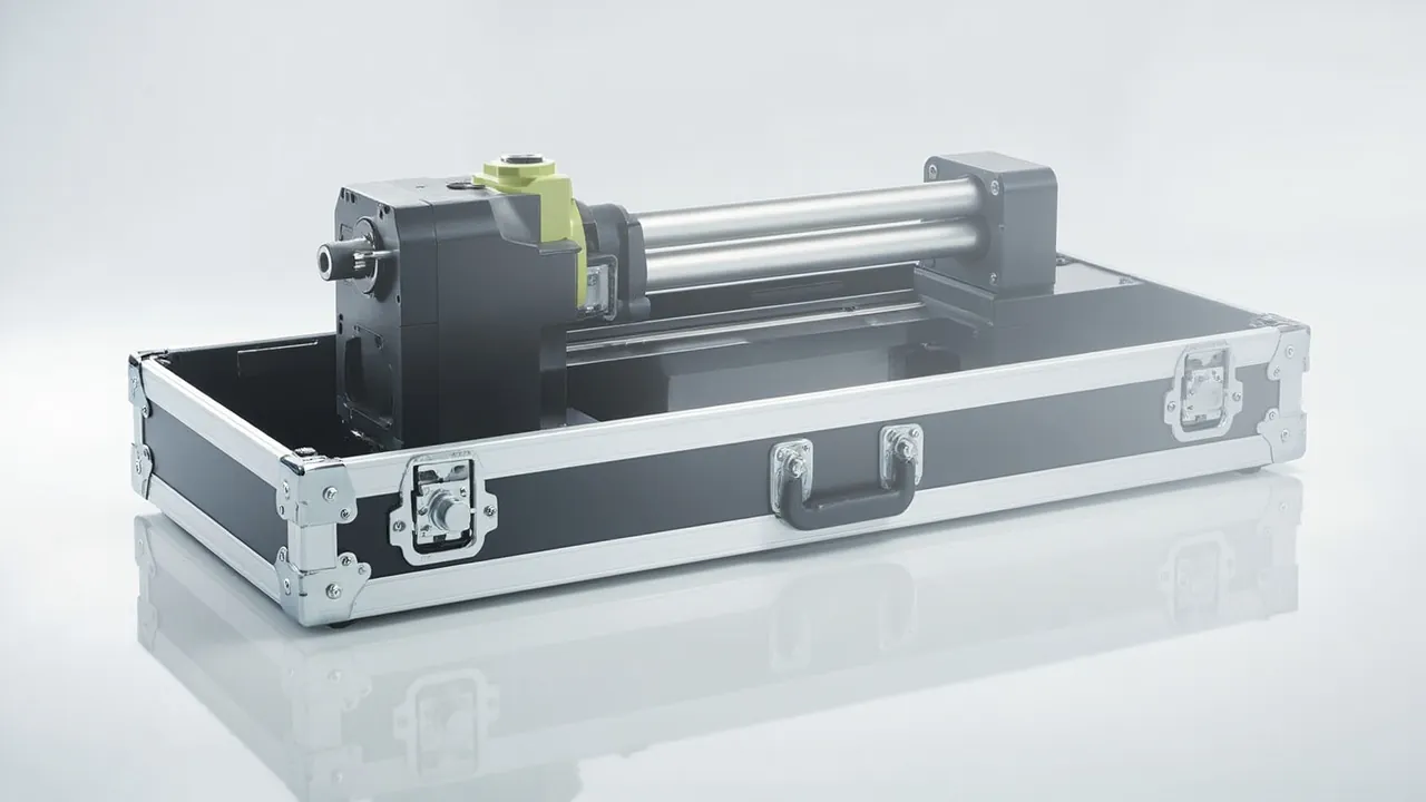
The most frequent damage to an electric cylinder or linear actuator in transit is not a dented housing. It is permanent bending of the screw and loss of accuracy in the servo motor encoder. These two failures share one root cause: residual freedom inside the case. If a component can move in its packaging, it develops inertia, and when that inertia acts on a slender screw or a precision encoder, a single journey can produce irreversible deformation. The packaging problem for this product family is therefore not shock absorption. It is stroke locking, six-degree-of-freedom constraint, and compartment isolation, in that order.
A typical rebuild scenario illustrates the point. A servo electric cylinder with 1.2 m of stroke arrives on site looking perfect. On power-up, full-stroke positioning repeatability is out of tolerance, and teardown reveals roughly 0.15 mm of bow at the middle of the ball screw. The transport record shows no significant damage to the crate walls, so there was never a severe drop. The real cause was that the cylinder was supported only at the two ends, leaving the screw overhung, and lateral vibration over a long journey excited the screw near its natural frequency until the deflection accumulated into plastic deformation.
This article works through the sequence of failure modes, component characteristics, stroke locking, compartmented inserts, moisture and grease preservation, test validation, and on-site reinstallation, giving an executable packaging method and pass or fail criteria. It is written for engineers and purchasing staff at automation equipment builders, system integrators, and transmission component traders, and it also serves as a technical basis for OEM and ODM custom insert programs.
Table of Contents
- Three High-Frequency Transport Failures and Their Detectable Symptoms
- Screw Type Determines Packaging Strategy
- Servo Motors and Encoders: Auditing the Electrical Weak Points
- Stroke Locking: Preventing Self-Extension and Retraction in Transit
- Compartment Decision: One Case or Two
- Grease Preservation, Moisture Control, and Corrosion Prevention
- Bending and Resonance Risk on Long-Stroke Screws
- Case Strength, Center of Gravity, and Stacking Load
- Package Validation Tests and Pass Criteria
- Additional Requirements for Cleanroom and ESD Scenarios
- Unpacking, Reinstallation, and Pre-Power Checks
- Volume Supply and OEM Program Execution
- Frequently Asked Questions
- Conclusion and Related Reading
Three High-Frequency Transport Failures and Their Detectable Symptoms
Define the failures first, and the packaging design acquires a target. Almost all transit damage to electric cylinders and linear actuators falls into the categories below, and each one has measurable, re-checkable symptoms.
| Failure Class | Physical Mechanism | Typical Trigger | Detectable Symptom | Reversibility |
|---|---|---|---|---|
| --- | --- | --- | --- | --- |
| Plastic screw bending | Lateral inertial load exceeds elastic limit | Long overhang, no mid support, whole-case vibration | Full-stroke repeatability error, periodic hand-turn resistance | Not reversible; screw replacement required |
| Encoder accuracy loss | Shock shifts scale relative to read head | No soft wrap at motor end, hard-point contact | Zero drift, alarms, low-speed crawl | Partially reversible; recalibration needed |
| End cap and seal damage | Bolted preload face fails after impact | Cylinder ends bearing load directly, stacking load on end cap | Grease weeping, wiper lip rolled, abnormal noise | Repairable by part replacement |
| Guideway scoring | Slider and rail micro-motion in transit | Slider not locked, no isolation | Running crawl, localized wear band | Light cases lapped; severe cases replaced |
| Cable and connector damage | Bent pins, broken shield | Cable trapped under the insert | Communication alarms, grounding faults | Repairable by part replacement |
This table is intended to double as an unpacking inspection checklist. Note in particular the irreversibility of screw bending. Once plastic deformation exceeds the elastic limit, it cannot be corrected on site back to factory accuracy. The screw must be replaced, and screw replacement usually pulls in coaxial realignment and preload re-setting, so downtime far exceeds expectation. Locking the screw's degrees of freedom at the packaging stage is therefore the single highest-return action available.
Screw Type Determines Packaging Strategy
Different screw types differ markedly in sensitivity to lateral load, contamination, and lubrication, so one packaging formula does not fit all.
| Screw Type | Load Characteristic | Transport Sensitivity | Packaging Focus | Protection Emphasis |
|---|---|---|---|---|
| --- | --- | --- | --- | --- |
| Ball screw | High accuracy, high transmission efficiency | Raceway brinelling, backlash change | Mid support plus full-stroke locking | Shock and contamination |
| Planetary roller screw | High thrust, strong shock resistance | Roller cage displacement | Axial locating and end stops | Axial creep prevention |
| Trapezoidal screw | Self-locking, simple structure | Thread corrosion, bronze nut wear | Moisture control first | Rust and humidity |
| Belt-driven linear module | Light load, high speed | Belt tension relaxation, tooth contamination | Maintain tension, keep oil off | Contamination and squeezing |
| Rack and pinion actuator | Heavy load, long stroke | Tooth face impact, joint face damage | Tooth protection, independent segment fixing | Impact damage |
One rule of thumb is widely used: when the ratio of screw length to nominal diameter exceeds 20, the packaging design must include mid support and axial preload locating; above 40, add a temporary process support sleeve or use a rigid carrier frame in addition to mid support. This is not optional, because a screw with a large length-to-diameter ratio already sags under its own weight, and transport vibration superimposes dynamic amplification on top of that static deflection.
For planetary roller screws, the critical item is fore-and-aft axial restraint. The internal roller cage can shift under axial shock, and after shifting the actuator shows reduced thrust or abnormal friction. Fit removable axial stops at both ends of the screw and have them removed on site after transport.
Servo Motors and Encoders: Auditing the Electrical Weak Points
A servo motor is usually supplied either integrated with the cylinder or as a separate unit. In both configurations the motor end is the highest-priority zone in the packaging.
Encoders. The gap between the disc and the read head in incremental and absolute encoders is typically on the order of tens of micrometers, so any shock that shifts the disc relative to the head corrupts the signal. Multi-turn absolute encoders retain position memory, but the mechanical zero offset after displacement is equally damaging. The packaging requirements are: full soft wrapping at the motor end with no unsupported overhang; the encoder end must never act as a load-bearing support point for the whole case; and no rigid hard points may be located in the case at that end.
Holding brakes. When a servo motor with a holding brake sits for long periods in the released state during transport, the friction surfaces can stick or the gap can change. Either keep the brake released and mark the state clearly, or place an instruction card inside the case specifying the pre-power checks.
Terminal boxes and connectors. Connector pins deform easily and the deformation is usually invisible. Cap every connector with a protective cover, coil cables separately, and secure them in dedicated slots with ties. Control the bend radius at not less than six times the cable outer diameter as an experience value. Never trap cables under the insert or route them through gaps between metal parts.
Cooling and ducting. Some servo motors carry an independent fan or duct structure, and fan blades fracture easily under impact. Where a motor has a fan cover, machine a clearance ring in the insert so the cover is not squeezed.
When drive units, cables, and encoder leads ship with the actuator, follow the graded electronic protection approach in servo motion controller transport case design points and keep drives in a separate package from mechanical parts.
Stroke Locking: Preventing Self-Extension and Retraction in Transit
This is where electric cylinder packaging diverges most from spindle packaging. An electric cylinder is a mechanism with a free direction of motion. Its stroke can change in transit because of vibration, self-weight, or residual pressure, dragging the screw and slider along inside the cavity.
The common locking methods and their applicability:
| Locking Method | Implementation | Advantage | Limitation | Suitable Situation |
|---|---|---|---|---|
| --- | --- | --- | --- | --- |
| Mechanical stop block | Removable blocks at both ends of the body | Simple, reliable, reusable | Needs installation space | Most electric cylinders |
| Fix at a stroke extreme | Retract fully or extend fully | Highest stiffness | Must confirm loads at that extreme | Short stroke, rigid body |
| Brake locking | Use the motor holding brake to hold position | No extra parts | Long-term engagement may stick | Servo with holding brake |
| Cavity-constrained stroke | Insert cavity itself limits travel | No added parts | Depends on insert machining accuracy | Fixed models in volume |
| Process tie rod | Temporary rod joining both ends | Resists tension and compression | Requires removal and documentation | Very long stroke |
The selection principle is to lock rather than merely limit where possible, and to use face contact rather than point contact. In practice the most robust combination is a mechanical stop block plus cavity-constrained stroke, where the block carries the main axial load and the cavity eliminates residual freedom.
One caution applies when the actuator is shipped at its fully retracted position: confirm the contact state between screw and nut at that extreme. In some designs the wiper seal is compressed at full retraction, and holding that state for a long journey creates permanent set in the rubber. In those cases ship at mid-stroke with a stop block instead.
Locking hardware must be removable and traceable. Place a removal instruction card inside the case listing the number of locking elements, their locations, and the removal sequence, so nothing is left in place and no overload alarm appears on first power-up.
Compartment Decision: One Case or Two
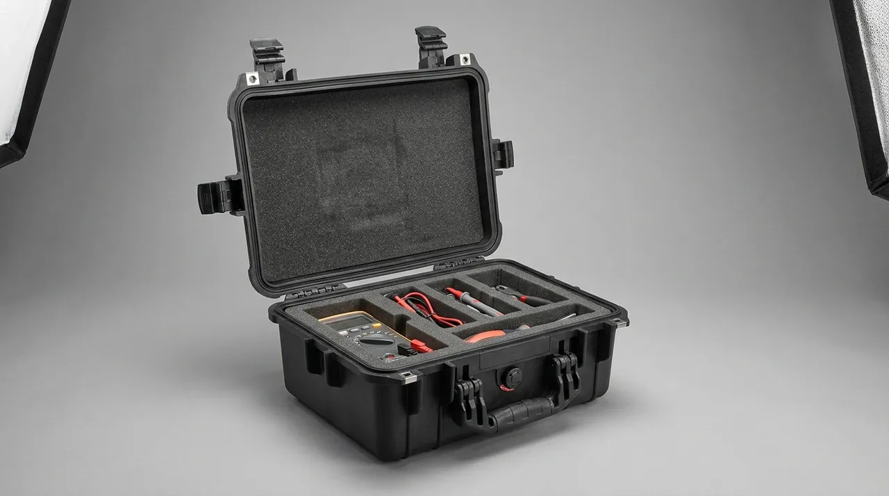
Whether the actuator, motor, and accessories travel together is a decision that must be settled early, because it drives case size, insert structure, and freight cost.
| Configuration | Structural Characteristic | Advantage | Risk | Recommended Scenario |
|---|---|---|---|---|
| --- | --- | --- | --- | --- |
| Same case, same cavity | One insert, one shared cavity | Smallest volume, lowest cost | Hard parts strike each other, motor takes shock | Not recommended |
| Same case, separate cavities | One insert, isolated cavities with dividers | Controlled volume, proper isolation | More complex insert machining | Recommended mainstream option |
| Same case, stacked layers | Motor above, cylinder body below | Low center of gravity, easy handling | Requires load-bearing divider design | When cylinder body is heavy |
| Separate cases | Body case plus electrical case | Optimal protection for each | More freight pieces | When electrical value is high |
| Modular | Main case plus removable inner tray | Flexible across many models | Tray management overhead | Many models, small batches |
From an engineering standpoint, same case with separate cavities is the default for the large majority of programs, balancing volume, cost, and protection. For the design method behind removable dividers, see protective case removable divider system design, whose modular logic suits actuator product lines that switch models frequently.
In a stacked-layer configuration, the interlayer divider must be stiff enough to transfer the upper load into the case walls rather than onto the cylinder body below. A common error is to use a foam pad as the layer separator. Foam creeps under sustained load, so late in the journey the upper layer sinks, the gap closes, and shock transfers directly.
Insert material selection follows the same logic as for precision machined parts: EVA for load bearing and precision locating, and EPE or PU for the outer cushioning layer. For cavity geometry and thickness design, see cushion liner design and selection inside protective cases.
Grease Preservation, Moisture Control, and Corrosion Prevention
Screws, guideways, and bearing locations are greased with a specific product at the factory, and the transport task is to keep that film from being squeezed out, contaminated, or degraded by moisture.
Preventing grease loss. High temperature accelerates oil separation and loss, and after a long hot journey it is not unusual to find grease migrated onto the insert. Design for a transport environment not exceeding 40 degrees Celsius under normal industrial storage and shipping conditions, keep cases out of direct sun on top of a container stack or in an open yard, and avoid direct contact between the case and hot ground.
Preventing contamination ingress. Grease is a strong adsorbent, and once dust or abrasive particles enter they produce a lapping effect in service. Keep the case interior clean, clean inserts before use, and never use recycled foam or a dusty old insert.
Moisture and corrosion. Trapezoidal screws, unplated nuts, and carbon steel end caps are the most corrosion-prone locations. Measures include a thin corrosion-preventive film plus vapor-phase corrosion inhibitor material plus desiccant humidity control. For seal material compatibility and moisture vapor transmission, see protective case seal material types and matching scenarios. Where a sealed case crosses climate zones, fit a pressure equalization valve to prevent seal deformation or moisture uptake through breathing.
Grease records. Supply a lubrication point list with the case, showing the grease type and quantity already applied, so the site can top up against it after reinstallation. This is not mandatory, but it is valuable in a warranty dispute.
Bending and Resonance Risk on Long-Stroke Screws
Long-stroke screw bending is fundamentally a dynamics problem and deserves separate treatment.
A screw can be approximated as a beam that is either simply supported at both ends or overhung at one end. Transport vibration spectra typically span 1 Hz to 50 Hz for road freight and up to roughly 200 Hz for rail and air. If the first lateral natural frequency of the screw falls inside the excitation band, resonance amplifies the response, and dynamic deflection can reach several times, sometimes more than ten times, the static value.
First lateral natural frequency is inversely proportional to the square of length and directly proportional to diameter. The intuitive consequence: longer and thinner screws have lower natural frequencies and are more likely to fall into the road transport excitation band. This is the physics behind the empirical length-to-diameter thresholds of 20 and 40.
Executable suppression measures:
- Add mid support. Halving the free length raises the natural frequency by roughly four times, making this the most effective single measure.
- Increase restraint stiffness. Support cannot consist of soft foam alone. Use a stiffer block such as hard EVA or an engineering plastic saddle at the midpoint, with a soft facing layer to protect the surface.
- Avoid periodic excitation. No gap may be left between insert and screw that allows free swinging, since impacts inside a gap create broadband excitation.
- Re-center the mass. Where the structure allows, keep the screw axis as close as possible to the overall center of gravity height to reduce vibration input.
For very long strokes, for example beyond 2 m, discuss a rigid carrier with segmented supports during the concept stage rather than stretching a standard case design. Such structures need tooling or dedicated machining, and the cost trade-off is covered in custom protective case mold cost analysis; using machined inserts at low volume and switching to tooling at volume is usually the more economical path.
Case Strength, Center of Gravity, and Stacking Load
Case design must answer three questions: can it carry stacking load, can it survive a drop, and is the center of gravity controllable during handling?
Stacking load. Calculate the bottom case as supporting three to five cases above it, and require the walls to carry that load. If wall strength is insufficient and the load ends up on the insert, every stack delivers load to the actuator itself, producing chronic damage. Apply a safety factor of 2 to 3 as an experience value to approximate dynamic amplification.
Center of gravity. The cylinder body usually weighs far more than the motor, and the center of gravity sits toward the body end. Design so the center of gravity approaches the geometric center of the case, for example by giving the lighter end a counterweight or an accessory cavity. Large offset causes tilt during lifting and manual handling, raising drop risk. Mark the center of gravity on the exterior.
Handling features. Any case above roughly 40 kg should have wheels and a telescoping handle. Above 80 kg, design lifting points or forklift pockets and clearly mark prohibited fork contact areas so the forks cannot press the insert or the cylinder body.
Sealing and protection rating. Electric cylinders are common in machining, washing, food, and packaging environments. Where the customer site involves washdown or high humidity, raise the case IP rating accordingly. For the boundaries between common levels, see IP waterproof ratings for protective cases and how to choose. Again, IP covers dust and water only and says nothing about vibration or impact.
Package Validation Tests and Pass Criteria
A packaging design must be confirmed by testing, and the tests must measure the part, not just look at the case.
A three-stage flow is recommended.
Stage one: conditioning. Condition per GB/T 4857.2 to represent the actual transport climate. For markets spanning climate zones, run both a hot humid cycle and a cold cycle.
Stage two: mechanical tests. Select drop, vibration, and compression according to the transport mode. For vibration, prefer random vibration over fixed-frequency sine, because a fixed frequency can happen to avoid the resonance region and deliver a false pass. Drop height follows package weight and handling method. Compression tests wall strength.
Stage three: functional re-verification. This is the stage most often skipped and the most important. After unpacking, check:
- Whether the full screw length turns by hand with periodic resistance or noise
- Radial runout at mid-screw with a dial indicator; as an experience criterion, not more than twice the factory value and not more than 0.05% of nominal diameter
- Whether the slider crawls over the full stroke
- Whether encoder zero has drifted or alarms appear
- Whether end caps and wipers weep grease or have rolled lips
Only when all three stages pass is the packaging design acceptable. When a customer or third party requires distribution cycle allocation, see ASTM D4169 distribution cycle testing and protective case validation. For third-party sampling decisions, see custom case acceptance sampling and AQL criteria.
Additional Requirements for Cleanroom and ESD Scenarios
Electric cylinders commonly serve two environments with additional requirements: cleanrooms in semiconductor, pharmaceutical, and display manufacturing, and electrostatic sensitive areas in electronics assembly.
Cleanliness. The biggest cleanroom packaging problem is particle generation from the packaging materials themselves. Ordinary EPE and talc-containing rubber parts continuously release particles that become contamination sources once inside the cleanroom. Measures include specifying low-particle-shedding insert materials with a cleaning step, wiping the case exterior before opening inside the clean environment, and supplying cleanroom packaging instructions. Align the cleanliness class with ISO 14644 and specify the opening environment class in the technical agreement.
Electrostatics. Where the actuator carries an encoder or drive unit, or serves an ESD protected area, the packaging needs static dissipative capability. Use conductive or static dissipative EVA for the insert, apply a conductive coating or select conductive material for the case, and fit a grounding terminal inside. For the underlying approach, see ESD shielding case design and material selection.
Surface cleanliness verification. Add an appearance cleanliness check after transport testing: wipe the screw and guideway surfaces with a lint-free cloth and inspect the residue. This reliably exposes packaging materials that shed particles.
Unpacking, Reinstallation, and Pre-Power Checks
A disciplined unpacking and reinstallation procedure reduces secondary human-induced damage.
Unpacking sequence:
- Open the case on level ground so internal parts cannot slide.
- Inspect the case, humidity indicator card, and tamper evidence, and photograph the state.
- Remove documentation and accessories first, then electrical items, then the actuator body.
- Retain all inserts and packaging material until no abnormality is confirmed.
Pre-power checklist:
- Confirm every transport locking element has been removed per the instruction card
- Push through the full stroke by hand once and feel for binding or noise
- Inspect the screw surface for rust, scoring, or missing lubricant film
- Inspect cable condition and connector pins
- Measure motor insulation resistance and compare against the shipping record
- Confirm the holding brake is free to actuate with normal clearance
- Verify grease quantity against the lubrication point list
Recommended first power-up: jog at low speed over a small stroke range first, watching current and temperature rise, then expand progressively to full stroke and rated speed. Skipping this step and running at full speed immediately turns any problem into secondary damage.
Volume Supply and OEM Program Execution
For equipment builders and integrators, packaging is a deliverable engineered item that belongs in supply chain management.
Suggested rollout sequence:
- Model mapping. Group actuators by bore, stroke, and mounting style, and identify model families that can share a case.
- Trial fitting. Build two to three physical pilot sets per family to confirm cavity, stops, and center of gravity.
- Test confirmation. Run full testing on the longest-stroke and heaviest representative models, and derive the rest by reasoned extrapolation with the basis documented.
- Document freeze. Issue controlled documents covering insert drawings, support point description, locking element list, unpacking instructions, and test reports.
- Spares management. Supply inserts, gaskets, desiccant, and locking elements as separate spares.
- Change control. Re-confirm packaging fit after any customer product revision; never assume the old design still applies.
For electric cylinder and linear actuator programs, JUNZHJIA typically issues a compartmented insert layout from the customer's stroke, bore, and mounting outline, marking support points, locating faces, and locking element positions; configures the cushioning layer for the transport mode and recommends test items; and supports OEM and ODM customization of case appearance, marking, and insert structure, with seals, desiccant, and pressure equalization valves matched to the actuator model, with an inspection and test record issued for each consignment. Electric-cylinder case production sits with Kexin New Materials (Guangdong) Co., Ltd., serving wholesale, agency and worldwide supply for motion-control integrators.

Frequently Asked Questions
Q: Should an electric cylinder be shipped fully retracted or fully extended?
A: Both approaches work, but under different conditions, and choosing wrongly is expensive. Shipping fully retracted keeps the case length minimal, which optimizes volume and freight cost, and it also concentrates the center of gravity and maximizes bending resistance, making it suitable for shorter strokes and rigid bodies. Several exceptions matter, however. In some designs the wiper or scraper seal stays compressed at the fully retracted position, and after a long journey this creates compression set, showing up as degraded sealing or grease weeping. In other designs the screw and nut make end contact at full retraction, so shock acts directly on threads or raceways. Shipping fully extended is the opposite trade: the long overhang lowers the screw natural frequency and increases bending risk, so it is generally not recommended on its own. The more robust engineering choice is mid-stroke shipping with removable stop blocks, avoiding long-term seal compression while locking the stroke positively. Final selection should follow the model's technical manual and the manufacturer's recommendation, and should be verified by physical testing.
Q: How do I judge whether a long-stroke screw needs mid support?
A: Start from the length-to-diameter ratio and correct for the transport mode. Divide screw length by nominal diameter. As an experience rule, above 20 you should seriously consider mid support, and above 40 mid support or a rigid carrier frame is essentially mandatory. The reason is that first lateral natural frequency is inversely proportional to length squared and proportional to diameter, so longer and thinner screws have lower natural frequencies and are more likely to land in the 1 Hz to 50 Hz road transport excitation band, where resonance can multiply dynamic deflection several times over. Transport mode correction matters as well: air and rail offer wider excitation bands, so the same ratio carries more risk than road. Mid support works by halving the free length, which raises natural frequency by roughly four times, a very large benefit. The support block should not be soft foam alone; use hard EVA or an engineering plastic saddle to carry load, with a soft facing layer protecting the screw surface.
Q: Can I just use a few foam pads instead of a fully formed insert?
A: For short-stroke, small, low-value products it can work, but not for precision servo actuators. Loose foam blocks provide cushioning without locating, so the part retains translation and rotation freedom inside the case. Transport vibration drives continuous micro-motion in those degrees of freedom, which on one hand repeatedly compresses the foam until it locally collapses and loses cushioning performance, and on the other hand lets the part leave its position after any significant impact, so subsequent shocks are carried by the case wall. A fully formed insert delivers cushioning, locating, and isolation simultaneously, and allows support stiffness to be set separately for the screw axis, motor end, and end caps. The test is simple: if any item can be pushed more than about 2 mm without removing the insert, locating is insufficient and the cavity needs redesign. Where volumes are too low to justify tooling, CNC-machined EVA inserts become cost effective from roughly a few dozen units.
Q: Why is the encoder so sensitive to transport, and what protection is genuinely effective?
A: The sensitivity comes from the operating principle. In an optical encoder the gap between disc and read head is typically tens of micrometers, and the grating pitch is at the same scale, so any shock or deformation that shifts the two relative to each other causes signal loss, jumps, or zero drift. Magnetic encoders are somewhat more tolerant but still precision components. The greater difficulty is that damage is often invisible: the exterior looks perfect while the signal is already abnormal. Four measures are effective. Treat the motor end as the highest-priority zone and give it full soft wrapping with no unsupported overhang. Never let the encoder end become a load-bearing support point for the case. Ensure no rigid hard points or metal members pass through the case at the encoder position. And after transport, re-measure zero and confirm with low-speed jogging. Supplying the factory zero record and insulation resistance record with the case lets the site compare values and is the most effective way to allocate transport liability. If the actuator and drive ship together, package them separately.
Q: How is desiccant quantity determined, and does a sealed case always need a pressure equalization valve?
A: Size desiccant by free internal volume, using 250 g to 500 g of silica gel or montmorillonite per 100 L as an experience value, where free volume means the net space after subtracting actuator and insert volume. Use the low end for journeys under two weeks and the high end with possible doubling for one to three months, then add a further margin for cross-climate shipping or mid-route inspection. Whether to fit a pressure equalization valve depends on seal tightness and transport conditions. In a fully sealed case, air freight, high-altitude transport, or large temperature swings can create a differential of tens of kilopascals, which deforms the gasket, makes the case hard to open, and can even damage the sealing structure. The differential also drives repeated breathing that carries external moisture inside and saturates the desiccant faster. A pressure equalization valve routes the breathing path into the valve body, where a moisture protection layer can be added, and it outperforms simply raising the IP rating. Fit a valve on any sealed actuator case intended for cross-climate transport.
Q: Once a transport test has passed, can it be skipped in future?
A: Not entirely, but it can be managed in tiers according to the type of change. Any change to the packaging design, insert structure, case dimensions, transport mode, or product model can alter the mechanical response and requires reassessment. A practical approach is to define clear tiers. For repeat orders with no change in model or packaging structure, an appearance and dimensional sample check is sufficient and mechanical testing need not be repeated. When the transport mode changes, for example road to air, or the stroke specification changes, redo vibration and drop testing. When case material or insert material changes, redo the full test set and retain the new report. When a customer introduces a new standard requirement, apply that standard. To control cost, select the longest-stroke and heaviest models in a family as test representatives for the full test set, and derive the rest by calculation and extrapolation with the basis documented and traceable. This controls cost while preserving an evidentiary basis in a dispute.
Q: Should a humidity indicator card go inside the case, and how is it read?
A: Yes, particularly for actuators containing carbon steel parts, trapezoidal screws, or unplated nuts. The purpose of the indicator card is to turn whether intervention is needed into a visual on-site judgement, avoiding both pointless desiccant replacement and missed replacement that leads to corrosion. Common five-spot cards correspond to thresholds of 10%, 20%, 30%, 40%, and 50% or 60% and indicate the internal humidity band by how many spots have changed color. Three usage points matter. Place the card where it represents true internal humidity, not against the desiccant or hidden behind foam. Provide an external viewing window or mark the card location on the case exterior, otherwise the case must be opened to read it, which defeats the seal. And record the initial state and inspection dates to build a log. A common criterion is to schedule desiccant replacement when the card reaches the 40% threshold, with the exact value set by the product's corrosion protection requirement and transit duration. Supplying the card and recording factory humidity also gives an objective basis in a customer claim.
Q: Is it more economical to ship the actuator and accessories in one case or two?
A: The decision turns on three variables: the value share of electrical items, the cost of additional freight pieces, and on-site handling complexity. Same-case separate-cavity packaging offers the best volume and logistics cost and lets one unpacking action verify everything, suiting situations where electrical value share is modest and the insert can reliably isolate shock. The risk is that a single incident affects mechanical and electrical items together, compounding the loss. Separate cases allow optimal protection for each, with the electrical case independently protected against moisture and static, while the mechanical case focuses on shock and load bearing. The cost is more freight pieces and separate on-site verification, raising management overhead. A balanced practice is to use same-case separate cavities for ordinary servo actuators, stacking motor above body with a load-bearing divider, and separate cases where high-value multi-axis drives are involved or where cleanroom or antistatic packaging is required. Either way, state the piece count and mapping on the packing list and apply matching batch marks to the exterior to prevent mismatching in transit.
Q: If a slight screw bow is found on site, can it be straightened and returned to service?
A: Self-straightening is not advisable. The accuracy of ball screws and planetary roller screws depends on raceway geometry and preload state, and any cold straightening alters raceway form and internal stress distribution. The exterior may look restored while accuracy and life become unpredictable. Whether the screw can remain in service should be decided from quantified data: measure radial runout at mid-length and at multiple points along the full length with a dial indicator and compare against the factory record; measure full-stroke repeatability and backlash; and check by hand for periodic resistance. As an experience guideline, if runout stays within twice the factory value and full-stroke operation is normal, the screw may be downgraded to a non-critical station with lower accuracy demand, but only with written confirmation from the equipment manufacturer. If periodic resistance, clearly increased backlash, or running noise has appeared, replace the screw. In all cases, retain the packaging material and transport records as the basis for a carrier or insurance claim, and notify the packaging supplier for failure analysis so the next batch does not repeat the problem.
Conclusion and Related Reading
The design logic for an electric cylinder or linear actuator case reduces to one sentence: lock the stroke first, constrain the six degrees of freedom next, and only then discuss cushioning and moisture control. Invert that order and you get a very strong case with a bent screw inside. Three main lines define the execution: establish mid support and axial restraint on the screw from its length-to-diameter ratio; treat the servo motor as the highest-priority electrical item with full soft wrapping and retained zero and insulation records; and build the insert as a three-part system of separate cavities, face-contact locating, and removable locking elements.
For purchasing and engineering staff, three concrete questions expose the capability of a packaging supplier. Can your insert design mark the support points and locating faces? Does the removal instruction for the locking elements travel with the case? And do your test reports contain functional re-verification data rather than appearance conclusions alone? A supplier who answers all three clearly is usually also the one who can help when something actually goes wrong.
Related Reading