

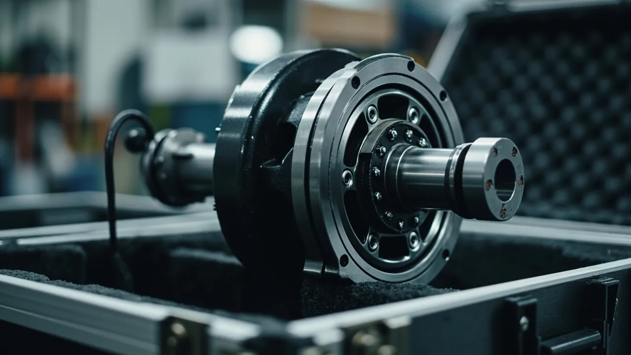
A CNC spindle case is not simply a box that holds a spindle. Its real job is to preserve the bearing preload, the taper geometry, and the tool-clamp actuation state of a spindle through every leg of transport and return logistics. A spindle replacement or rebuild typically costs 15% to 30% of the original machine price, and a meaningful share of those rebuilds are not caused by normal service life at all. They are caused by accumulated shock, moisture, and contamination picked up during factory dispatch, plant-to-plant relocation, or overseas delivery. The practical conclusion is straightforward: a spindle assembly must be packaged to the dual standard of a precision metrology instrument and a heavy machined component, never as an ordinary machined part.
Four failure modes interact inside a spindle assembly. The first is brinelling of bearing raceways under static shock. The second is corrosion of the taper bore and mounting face in humid air. The third is drift in the preload state of the disc-spring stack and unclamp cylinder. The fourth is damage to the encoder, drive cabling, and connectors inside a motorized spindle. What makes all four dangerous is that they are invisible at the moment of unpacking and only surface after the spindle is installed: runout out of tolerance, abnormal temperature rise, incomplete tool change, or positioning drift. This article addresses those four risks with a working method covering insert compartment design, cushioning and vibration isolation, sealing and moisture control, test verification, and receiving inspection, and it closes with the acceptance points that matter for batch supply and OEM programs. It is written for engineers and purchasing staff at machine tool builders, spindle rebuild shops, and equipment trading companies.
Table of Contents
- Why Spindle Transport Is Harder Than Whole-Machine Transport
- Breaking Down the Spindle Assembly and Grading Fragility
- Bearing Sets: How Static Shock Becomes Permanent Brinelling
- Taper Bore, Mounting Face, and Tool Clamp: The Hidden Moisture Failures
- Motorized Spindles: Encoders, Drive Cables, and Cooling Ports
- Insert Compartment Design: Support Points, Locating Faces, and Load Paths
- Cushioning Design: Working Backward From an Allowable G Level
- Sealing and Ingress Protection: Where IEC 60529 and GB/T 4208 Apply
- Case Structure, Latches, and Return-Trip Durability
- Transport Test Plan: Combining ISTA and GB/T 4857
- Marking, Shipping Documents, and Receiving Inspection
- Purchasing and OEM Supply Decision Checklist
- Frequently Asked Questions
- Conclusion and Related Reading
Why Spindle Transport Is Harder Than Whole-Machine Transport
A complete machine tool has inherent transport advantages. The bed is heavy, the structure is stiff, and the center of gravity sits low, so the machine resists vibration far better than the parts inside it. Once a spindle ships as a standalone unit, all of that protection disappears. What remains is a slender shaft-and-bearing train with stiffness and damping at their least favorable values.
Damage statistics cluster into three scenarios. The first is single-piece air freight or less-than-truckload shipping, where there is no pallet ballast, stacking is uncontrolled, and loading depends on manual lifting. The second is a spindle shipped while still mounted in the machine, which appears protected by the machine enclosure but is actually exposed to continuous excitation, because whole-machine transport vibration travels through the bed directly into the spindle nose. The third is the rebuild round trip, where a spindle moves between the repair shop and the customer several times and packaging gradually degrades to a wooden crate plus bubble wrap.
One factor is routinely underestimated: value density. By weight, a spindle may be worth only tens of dollars per kilogram. By cargo value, the same spindle can reach several hundred or even over a thousand dollars per kilogram. That means the packaging cost is a small fraction of cargo value while the cost of a damaged spindle is enormous, so packaging investment returns far more here than on general machined parts. As an order of magnitude, a purpose-designed compartmented insert plus cushioning system for a spindle usually costs 1% to 3% of the spindle's value and removes most of the early-life failure risk in the transport chain.
Breaking Down the Spindle Assembly and Grading Fragility
Before designing anything, list the subsystems of the spindle being shipped and grade each one. Sensitivity to shock, vibration, and moisture varies enormously between subsystems. Designing everything to the strictest level wastes money; designing to the loosest level guarantees a failure.
| Subsystem | Primary Material | Shock Sensitivity | Vibration Sensitivity | Moisture Sensitivity | Typical Damage Signature |
|---|---|---|---|---|---|
| --- | --- | --- | --- | --- | --- |
| Front and rear bearing sets | Bearing steel, ceramic balls | Very high | Very high | High | Raceway brinelling, preload drift |
| Taper bore and mounting face | Alloy steel, carburized layer | High | Medium | Very high | Rust spots, taper scoring, runout out of tolerance |
| Disc-spring clamp stack | Spring steel | Medium | Low | High | Reduced clamping force, corrosion seizure |
| Unclamp cylinder | Aluminum, seals | Medium | Medium | Medium | Seal aging, sluggish actuation |
| Motor stator and rotor | Silicon steel, copper winding | High | Medium | Very high | Insulation resistance drop, wet winding |
| Built-in encoder | Glass or magnetic scale | Very high | Very high | High | Signal loss, zero-point drift |
| Drive cable and connectors | Copper, engineering plastic | Low | Medium | Medium | Bent pins, intermittent contact |
| Cooling and air-purge ports | Stainless steel, brass | Low | Low | Low | Thread damage, seal face nicks |
The rule for reading this table is to stack toward the stricter requirement. If a bearing set and an encoder travel in the same case, the case must meet the encoder's shock and vibration requirements rather than an average of the two. In practice, a motorized spindle case containing an encoder should have its allowable shock level tightened by one additional step relative to a purely mechanical spindle.
Bearing Sets: How Static Shock Becomes Permanent Brinelling
Machine tool spindle bearings are, in the overwhelming majority of cases, angular contact ball bearings, cylindrical roller bearings, or a combination of both, already matched, preloaded, and run-in at the factory. Static shock in transit produces a specific class of damage: brinelling at the contact between raceway and rolling element. These dents show almost no symptom at low speed and light load. Once the spindle enters its high-speed range, however, the brinelled locations generate a periodic excitation that appears as a sudden jump in vibration and an abnormal temperature rise.
The governing parameter is allowable shock acceleration, usually expressed as a G level. As engineering experience values, a preloaded precision bearing set in a packaged assembly should generally be held within 25 G to 40 G (with a pulse duration on the order of 6 ms to 11 ms). For a motorized spindle containing an encoder, tightening further to 15 G to 25 G is advisable. These are experience bands and not standard-mandated figures; the spindle manufacturer's allowable value takes precedence and must be confirmed by physical package testing.
Three engineering points matter most:
- Treat axial and radial directions separately. Angular contact bearings are more sensitive to axial shock, yet a cushioning design that only handles vertical drop will let lateral shock pass straight through the insert wall into the bearing housing.
- Avoid hard-point contact. If the insert only presses against the bearing seat, shock force concentrates there. Support should land on the housing outer ring or the flange face, where stiffness is higher.
- Prevent rotation and axial creep in transit. Any axial freedom lets transport vibration drive micro-motion, and long-term fretting destroys preload just as effectively as a single impact. The insert must limit axial displacement to within 0.5 mm.
Taper Bore, Mounting Face, and Tool Clamp: The Hidden Moisture Failures
Spindle taper bores (BT30, BT40, BT50, HSK-A63, ISO series and similar) and mounting faces are mating surfaces with tolerances typically in the micrometer range. Corrosion is the leading failure cause here, and it almost always starts from condensation rather than direct liquid ingress.
The most dangerous combination in transport is loading in hot humid air, shipping through cold humid air, and then opening the case during warm-up. Day-night temperature swings inside a container or cargo hold push internal air repeatedly across the dew point, and water vapor condenses on metal surfaces. Residual cutting fluid or incomplete rust-preventive films on the spindle make the electrochemical corrosion conditions worse.
Practical measures:
- Apply corrosion protection before packaging. Coat the taper bore and mounting faces with a thin rust-preventive grease or use vapor-phase corrosion inhibitor (VCI) materials. Aim for a visible film with no pooling. Never apply a thick layer; thick grease turns into sludge under transport vibration and traps abrasive particles.
- Control internal humidity. Combine desiccant (montmorillonite or silica gel) with a humidity indicator card. As an experience value, allow 250 g to 500 g of desiccant per 100 L of free internal volume, with a multiplier for the expected transit period. If the case is fully sealed, consider fitting a pressure equalization valve so that the seal does not bulge from a pressure differential or breathe in moisture. For the design rationale, see the role and selection of pressure equalization valves in protective cases.
- Combine VCI with desiccant. VCI protects the metal surface in the vapor phase while desiccant lowers bulk humidity, and the pair outperforms either alone. For seal material compatibility and moisture vapor transmission, see protective case seal material types and matching scenarios.
On the tool clamp side, the disc-spring stack has already been set to a defined clamping force at the factory. Accidental actuation of the unclamp cylinder, or an axial impact, can shift that state. Cap and mark the unclamp hydraulic or pneumatic port for transit, and give the unclamp cylinder its own compartment so it never shares space with hard components.
Motorized Spindles: Encoders, Drive Cables, and Cooling Ports
A motorized spindle is the hardest spindle type to protect because it integrates precision mechanics, motor windings, sensors, and a cooling circuit inside one slender body.
Encoders. Optical encoders are extremely sensitive to shock and vibration. Grating pitch is typically in the 20 μm to 40 μm range, so any deformation or impact that shifts the disc relative to the read head can corrupt the signal. In the transport design, treat the encoder end as the highest-priority zone, with full soft wrapping in the insert and absolutely no unsupported overhang.
Windings and insulation. Motor windings are moisture sensitive, and a drop in insulation resistance after getting wet can cause an inter-turn short the moment power is applied. Beyond VCI and desiccant, measure and record insulation resistance before shipping and include the record in the case. Having the customer re-measure on arrival and compare is the single most effective way to prevent disputes.
Cooling and air-purge ports. Coolant jacket ports and air-purge ports on a motorized spindle are usually threaded or quick-connect. The most common transit damage is thread impact and seal face scratches. Fit plastic protective caps and provide dedicated recesses in the insert so the ports never carry stacking load directly.
Drive cables. Coil and secure cables separately inside the case, keeping the bend radius at not less than six times the cable outer diameter as an experience value, and cap the connectors against dust. Never route cables under the insert or through gaps between metal parts. When a servo drive package ships with the spindle, the electronic protection concepts in servo motion controller transport case design points apply directly.
Insert Compartment Design: Support Points, Locating Faces, and Load Paths
The insert is what actually delivers the case's protective performance. The shell only prevents loss and water ingress; cushioning and positioning come entirely from the insert.
A workable design sequence:
- Establish the datum. Use the spindle's flange mounting face or housing outer diameter as the locating datum. This is simultaneously the stiffest and least deformable area.
- Set support point count and position. A slender spindle needs at least three supports (both ends plus the middle). For a length-to-diameter ratio above 12, use four. Support points must avoid the taper bore, oil seals, and encoder.
- Define compartment boundaries. Give the spindle, accessories (pull studs, tool holders, wrenches), electrical items, and documentation their own compartments. Hard components must be separated from one another.
- Choose the locating method. Prefer face contact over point contact. Larger contact area means lower unit pressure and far less chance of a local dent under shock.
- Plan the handling path. The insert must allow extraction without prying and insertion without hammering. This usually means cut-in hand slots or folded pull tabs.
For material selection, spindle case inserts commonly combine EVA, EPE, PU, and XPE foams. EVA offers good resilience and forming accuracy and suits load-bearing and precision locating. EPE absorbs energy well but lacks structural stiffness and belongs in the outer cushioning layer. For a direct comparison, see protective case foam material comparison and selection, and for the forming process itself, see the custom EVA foam insert molding process.
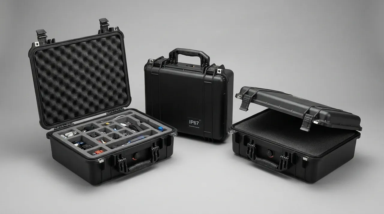
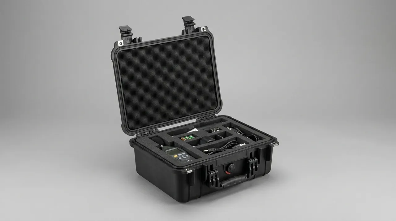
One detail is frequently missed: an insert must not only support the part, it must also cap it. The lid insert must press against the base insert so the spindle is constrained vertically as well. A design with base support and a hollow lid is useless the moment the case is tipped during transport.
Cushioning Design: Working Backward From an Allowable G Level
Cushioning should be derived from the allowable shock value, not from the thickness of foam on hand. A common engineering approach is the energy method: the potential energy of a drop is absorbed by the cushioning material, and the material's energy absorption per unit volume determines the thickness required.
A practical estimation flow:
- Establish the packaged weight m and the credible drop height h. Take h from the applicable ISTA or GB/T 4857 level; for manually handled items, 600 mm to 900 mm is common.
- Compute the impact energy E = m·g·h.
- Choose a target allowable acceleration, for example 20 G, and derive the energy density and bearing area the cushion must provide.
- Size the thickness from the foam's stress-strain curve, not from its density, then apply a safety factor of 1.3 to 1.5.
- Verify with a physical drop test. The design passes when measured acceleration stays within the limit.
The key point is that foam selection depends on the stress-strain curve, not on density. Two EVA foams of identical density can differ by more than a factor of two in plateau stress because of formulation and foaming differences. If only density is available, request compressive strength data from the supplier or test a physical coupon.
Cushioning should also be directionally differentiated. Vertical travel is usually generous and can take a thick cushion. Horizontal travel is limited by case wall dimensions and often allows only a thin cushion, in which case the solution is to reduce lateral displacement through insert locating features rather than to overstuff foam.
Sealing and Ingress Protection: Where IEC 60529 and GB/T 4208 Apply
The sealing class determines whether the case resists rain, spray, dust, and short-term immersion. IEC 60529 and the Chinese standard GB/T 4208 use the same IP classification, and the commonly specified levels break down as follows:
| IP Rating | Dust | Water | Typical Transport Scenario | Fit for Spindle Assemblies |
|---|---|---|---|---|
| --- | --- | --- | --- | --- |
| IP54 | Partial dust protection | Splash resistant | Domestic road, in-plant transfer | Moderate; short haul only |
| IP55 | Partial dust protection | Jet resistant | Ordinary export, rainy regions | Common entry level |
| IP65 | Dust tight | Jet resistant | Sea freight, on-site storage | Recommended for precision spindles |
| IP67 | Dust tight | Short immersion | Open yard stacking, wet transfer | Recommended for high-value spindles |
| IP68 | Dust tight | Continuous immersion | Special extreme cases | Usually unnecessary |
The selection principle is not "higher is always better." IP67 and above generally means a more complex sealing system, higher opening and closing effort, and higher cost. If desiccant is used inside, a fully sealed case also prevents internal moisture from escaping, so the desiccant saturates quickly. In that situation, a pressure equalization valve, as linked earlier, is more rational than chasing a higher IP number.
One clarification matters: an IP rating describes dust and water resistance only. It says nothing about shock, vibration, or moisture control capability. A complete spindle case specification should state the IP rating, the package drop test results, and the internal humidity control method together.
Case Structure, Latches, and Return-Trip Durability
Spindle cases are often designed as returnable containers, so structural durability and seal life matter as much as initial protection.
- Shell material. For high-value, long-cycle returnable use, specify copolymer polypropylene (PP) injection-molded shells, which outperform homopolymer PP in impact and low-temperature behavior. For one-way shipping, a plywood crate with a sealed inner bag is adequate.
- Hinges and latches. Hinge pins should be captive. Latches should include a secondary lock to prevent accidental release. For sealing architecture at hinges and latches, see toolbox hinge, latch, and seal structure explained.
- Gaskets. Prefer molded silicone or EPDM gaskets over spliced corner joints, which are leak paths. Target 30% to 40% compression on the gasket.
- Wheels and handles. Any case above roughly 40 kg should have wheels and a telescoping handle to reduce manual handling drop risk.
- Stacking load. The case must carry transport stacking load, typically calculated as the bottom case supporting three to five cases above it, with load carried by the walls rather than the insert.
Transport Test Plan: Combining ISTA and GB/T 4857
Whether a packaging design is acceptable must be settled by testing, not opinion. A spindle case program should combine the following:
| Test | Reference Standard | Key Parameters | Pass Criteria |
|---|---|---|---|
| --- | --- | --- | --- |
| Vibration | ISTA series / GB/T 4857.7 | Random vibration spectrum, duration | No insert displacement, no part movement |
| Drop | ISTA series / GB/T 4857.5 | Drop height, faces impacted | Measured acceleration within allowable G |
| Compression | GB/T 4857.3 | Load, duration | No instability, no permanent deformation |
| Temperature and humidity conditioning | GB/T 4857.2 | Temperature, humidity, duration | No condensation or corrosion on opening |
| Full package performance | ASTM D4169 | Distribution cycle allocation | All applicable items pass |
Condition the package for temperature and humidity before testing to represent the real route, and after testing perform functional checks rather than a visual inspection alone. A spindle must have its taper runout, insulation resistance, and rotational freedom re-verified. When the distribution cycle allocation must be agreed with a customer or third-party laboratory, see ASTM D4169 distribution cycle testing and protective case validation. For environmental test methods generally, see MIL-STD-810H and protective case environmental testing, noting that this standard is used here purely as an environmental test methodology reference and does not constitute a military certification. When a third-party inspection body applies AQL sampling, see custom case acceptance sampling and AQL criteria.
Marking, Shipping Documents, and Receiving Inspection
The marking system on a spindle case directly affects site productivity and liability allocation.
Exterior marking should include:
- Product name, model, and serial number, matching the spindle nameplate
- Net weight, gross weight, and case external dimensions
- Center of gravity location and this-side-up marking
- Lifting points and prohibited forklift contact areas
- Keep-dry, protect-from-vibration, and fragile graphical symbols
- Customer part number and delivery address
Shipping documents should include:
- Packing list and accessory list
- Factory inspection report covering taper runout, insulation resistance, and clamping force
- Corrosion protection record and desiccant installation date
- Unpacking instructions and reinstallation cautions
- Warranty and rebuild contact details
Receiving inspection should run step by step:
- Check the case for damage and moisture, and verify the humidity indicator card has not changed color.
- Photograph the original condition before opening.
- Remove the spindle and inspect the taper bore and mounting face for rust and scoring.
- Turn the spindle by hand and feel for binding, noise, or play.
- Measure insulation resistance and compare against the shipping record for motorized spindles.
- Verify accessory completeness and cable condition.
- If anything is abnormal, retain all packaging material as evidence for the claim.
The last point deserves emphasis: packaging material is evidence in a dispute, and once discarded the transport conditions can never be reconstructed.
Purchasing and OEM Supply Decision Checklist
For machine tool purchasing groups, spindle rebuild shops, and export traders, work through the following table item by item.
| Decision Item | What Must Be Specified | Common Mistake |
|---|---|---|
| --- | --- | --- |
| Spindle type and size | Mechanical or motorized, flange spec, length, weight | Supplying a model number without an outline drawing |
| Fragile component list | Encoder location, cooling port locations | Assuming the whole body is equally robust |
| Allowable shock value | Obtain from the spindle manufacturer | Applying a generic machined-part standard |
| Protection rating | Based on transport and storage scenario | Requiring IP67 across the board |
| Return cycle count | One-way or returnable | Quoting a returnable case for one-way use |
| Insert configuration | Compartment count, accessory pockets | Spindle and accessories sharing one cavity |
| Marking and documents | Language, label format, shipping documents | Not specifying language, forcing rework |
| Acceptance method | AQL sampling or 100% inspection | No defined acceptance basis |
| Spares and service | Seals and inserts supplied separately | Scrapping the whole case when an insert wears |
JUNZHJIA's standard approach on programs of this kind is to issue an insert layout drawing from the customer's spindle outline drawing and fragile component locations, with support points and locating faces marked; to configure the cushioning layer from the transport mode and allowable G level and recommend a test plan; and to support OEM and ODM customization of case appearance and marking, seal and desiccant selection matched to each model, and factory inspection and test reports supplied with each shipment. Machine-tool spindle case programmes are produced by Kexin New Materials (Guangdong) Co., Ltd., covering wholesale, agency and global supply for spindle and machine-tool builders.
For machine tool builders placing volume orders, the recommended sequence is a small pilot build plus full test validation: assemble three to five physical pilot sets, complete vibration and drop testing, confirm no displacement and no exceeded limits, and only then release to volume. The extra front-end effort prevents an entire batch from being scrapped.

Frequently Asked Questions
Q: Does a spindle case really need IP67, or is IP65 enough?
A: The decision depends on the transport and storage scenario, not on the spindle price. For domestic full-truckload road freight with short-term covered warehouse storage, IP55 or IP65 covers most needs. IP67 only becomes meaningful for sea freight, open storage yards, construction site storage, or transfer through rainy regions. Two clarifications are worth repeating. First, an IP rating covers dust and water only and says nothing about vibration or impact resistance, so never treat it as the whole performance picture. Second, if desiccant is used and the case is fully sealed, internal moisture cannot escape and the desiccant saturates quickly. In that case IP65 plus a pressure equalization valve is more rational, because the valve controls the breathing path, and the inside of the valve can be protected against moisture. Final selection should combine expected transit duration, storage conditions, and inspection frequency, and should be validated by full package testing. In practice, most spindle programs settle on IP65 for domestic and covered-warehouse routes and IP67 only where the case will genuinely sit outdoors or cross water, because the higher rating adds cost and opening effort without improving shock or vibration protection at all.
Q: Should the spindle be coated with rust preventive before packing, and how thick?
A: Yes, but the principle is thin and uniform rather than generous. Taper bores, mounting faces, and journals should carry a thin rust-preventive grease film or be protected with vapor-phase corrosion inhibitor materials, leaving a visible film without pooling. Thick application causes three real problems. First, under transport vibration the grease forms sludge that traps dust and abrasive particles, turning into lapping compound. Second, a heavy film inside the taper interferes with assembly feel, so the customer has to remove it with solvent, adding labor and risking damage to the carburized layer. Third, a thick layer masks surface defects so existing corrosion is not discovered during receiving inspection. On motorized spindles, never apply grease to the windings; control moisture with VCI and desiccant only. Fix the application method, quantity, and inspection method in the process documentation, and include a corrosion protection record with each shipment. Where a spindle will be stored for an extended period before installation, pair the thin film with desiccant and consider a vapor barrier bag, because the film alone only slows surface attack while humidity continues to cycle with temperature.
Q: How do I know whether an insert design is actually acceptable?
A: Physical full-form trial fitting plus transport testing is far more reliable than reviewing a drawing. During trial fitting, check four things: whether the spindle shifts noticeably after insertion; whether the upper and lower inserts press against each other; whether extraction requires prying; and whether accessories are fully separated from the spindle. After transport testing, re-check whether the spindle has moved within the insert or left compression marks, whether taper runout matches the factory value, and whether rotation is still smooth. As a rule of thumb, a sound insert lets you shake the closed case without hearing internal impacts, and the spindle position does not change after a 180-degree roll. Where possible, apply witness marks at the insert-to-spindle contact points so any relative movement is visible after transport. A further check that catches subtle problems is to weigh the packed case before and after testing and compare the center of gravity position: a shift indicates the spindle has migrated inside the insert even when the exterior looks untouched. JUNZHJIA supports insert layout proposals and trial-fit verification.
Q: How is desiccant quantity estimated, and does it need replacing mid-transit?
A: A working method is to size by free internal volume: 250 g to 500 g of silica gel or montmorillonite desiccant per 100 L, then apply a multiplier for transit duration, using the low end for trips under two weeks and the high end with a possible doubling for one to three months. Free volume means the net space after subtracting the spindle and insert, not the external case volume. As for replacement, a well-sealed case generally does not need replacement within three months. Beyond three months, or after any mid-route opening, replace the desiccant before closing and record the date. A more practical approach is to fit a humidity indicator card or an externally visible humidity window, so the decision to replace is made visually on site rather than blindly, avoiding both waste and missed changes. If the case is fully sealed and fitted with a pressure equalization valve, account for moisture exchange through the breathing path and add a desiccant chamber inside the valve where necessary.
Q: Does the spindle need axial restraint inside the case, and will that damage the bearings?
A: Axial restraint is necessary, and how it is applied directly determines whether the bearings suffer. If the spindle has axial freedom in transit, vibration drives reciprocating micro-motion, and long-term fretting destroys the established preload, showing up after installation as elevated temperature rise or abnormal vibration. The correct method is face-contact restraint: machine limiting faces in the insert that bear against the flange face or housing outer diameter, holding axial displacement within 0.5 mm, with the load carried by a large contact area. Never press screws against or clamp precision mating surfaces such as the taper bore. That kind of point or small-area contact creates localized high pressure under shock and produces brinelling directly. The limiting feature itself should also have some compliance so it does not create a hard point that transmits shock straight into the bearings. After design, verify spindle axial play by transport testing, and repeat the check on a sample from each production batch rather than relying on a single qualification test.
Q: Can a motorized spindle and a mechanical spindle share the same packaging design?
A: Sharing is not recommended. The difference lies mainly in the electrical content. A motorized spindle contains stator and rotor windings, a built-in encoder, drive cabling, and cooling ports, all of which tolerate moisture, shock, and vibration less well. The encoder is highly vibration sensitive, the windings are moisture sensitive, and the connectors are easily damaged by impact. A motorized spindle case therefore usually needs full soft wrapping at the encoder end, an allowable shock value tightened by one step, an insulation resistance recording step, and protective caps on all ports. A mechanical spindle's risks concentrate in bearing brinelling, taper corrosion, and tool clamp condition, so its packaging can be relatively simpler. If a company builds both types, maintain two insert templates and two sets of test limits rather than sharing one, because the motorized end will otherwise become the recurring failure point. A simple way to enforce the separation is to give the two insert templates different cavity colors, so a mixed build is visible at a glance on the packing line.
Q: Can a spindle case be reused for return trips, and how is life assessed?
A: Yes, but with defined inspection rules. A common approach is to set a maximum cycle count and inspect critical items periodically: whether the shell has cracks or permanent deformation; whether the gasket has hardened, taken a compression set, or detached; whether hinge pins are loose; whether latches still lock fully without play; and whether the insert cavities have relaxed or gone out of tolerance after repeated handling. As an experience value, an injection-molded shell with a molded silicone gasket supports dozens to well over a hundred trips under normal use, but the insert life is typically shorter than the shell life, especially at load-bearing points that gradually collapse. Manage the insert as a separate spare part and replace it when cavities relax, rather than scrapping the whole case. For a structured method, see protective case service life and replacement criteria. Keeping a simple log of trips, inspection findings, and parts replaced turns this from guesswork into a scheduled maintenance item.
Q: What compliance issues apply to wooden crates and inserts for export shipments?
A: Wood packaging material is subject to ISPM 15, the international standard for phytosanitary measures, which requires heat treatment or fumigation and the corresponding mark. This is mandatory in most importing countries, and a missing mark can result in return shipment or destruction. Plywood and other engineered wood panels generally fall outside ISPM 15 scope, but confirm the destination country's specific requirements with the customer. If the spindle retains coolant residue or grease, some countries impose declaration and disposal requirements, so drain and clean before packing. For package performance testing, follow the standard the customer specifies, such as an ISTA series protocol or an ASTM D4169 distribution cycle. If third-party inspection is required, allow lead time in the schedule. Situations involving hazardous goods, such as certain batteries or pressure vessel accessories, follow separate rules, although spindles and their ordinary accessories are generally not in that category. Confirming all of this before the first export shipment is far cheaper than resolving a customs hold after the container has sailed.
Conclusion and Related Reading
A spindle case exists to resolve a genuine contradiction: protecting a precision instrument while carrying a heavy metal mass. Keeping to four lines of engineering logic prevents the design from drifting: cushion the bearing set against shock, protect the taper bore and mounting face against moisture, shield the electrical components of a motorized spindle against vibration and humidity, and make the insert constrain by face contact rather than point contact. The remaining work is to write the allowable values, test items, and acceptance criteria into documents, so packaging becomes a deliverable engineered part rather than a matter of operator habit.
For buyers, price and shell finish are the least informative things to compare. Look instead at three capabilities: whether the supplier can lay out a compartmented insert to your spindle's actual outline; whether they can explain the support points and locating faces; and whether they can supply full package test results and per-shipment inspection records. Those three determine whether the packaging saves the spindle or loses it when something goes wrong.
Related Reading