

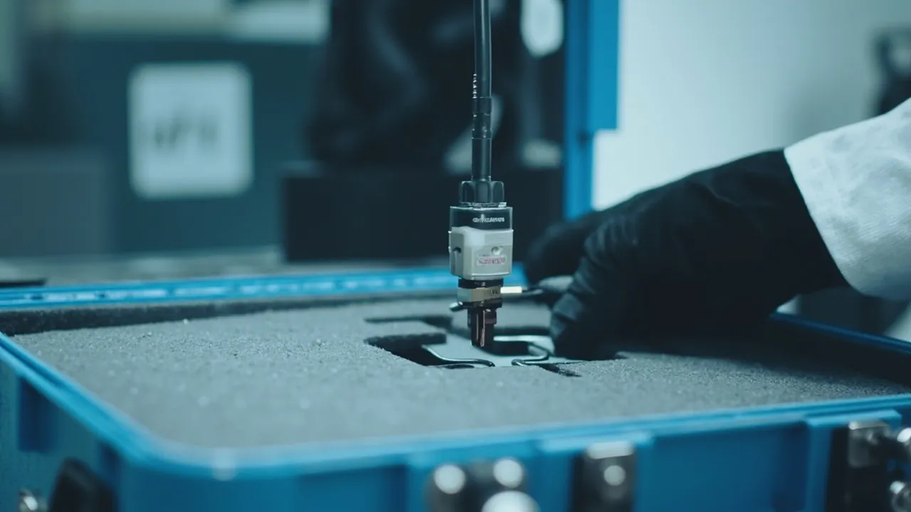
Wire bonder service parts have a distinctive commercial profile: the expensive part is never the machine frame — it is the energy chain inside the bond head, running from transducer to capillary, together with the tension-control path in the wire-feed system that meters a gold wire only a few tens of microns thick. When either of those loses its calibration in transit, the symptom after installation is not a machine that fails to run. It is a machine that appears to run: bonds form normally, but pull-test scatter widens, or a specific batch shows neck fractures. The central conclusion of this article is that a wire bonder parts case must be engineered as an overlay of three disciplines at once — optical-grade cleanliness, precision moving parts, and fine metallic wire consumables. Treating it as ordinary electronics packaging produces hidden yield loss.
Bonding is more parameter-sensitive than most semiconductor processes. Ultrasonic power, bond force, bond time, and capillary touchdown position are validated against a process window at the factory, and all four rest on the geometric datums of the bond head mechanism. A vibration event that looks harmless in transit can shift the transducer mounting face slightly, or indent a roller bearing in the wire-feed path, and what changes is the wire tension curve and the ultrasonic coupling efficiency. The difficulty is that nothing alarms; the only evidence is a slow upward creep in failure rate.
This article works through failure modes, component modules, packaging engineering, and verification and recovery, and it presents the technical points in a form that can be dropped directly into a purchase specification or an acceptance document. It is written for equipment engineers at assembly and test houses, dealers in wire bonder spares, and machine refurbishment companies.
Table of Contents
- Risk Profile for Bond Head and Wire-Feed Components in Transit
- Module Breakdown and Fragility Matrix for Wire Bonders
- Ultrasonic Transducers and Capillaries: The Weak Points on the Energy Chain
- Wire-Feed Systems: Why Tension-Control Parts Fear Vibration
- Precision Rails and Linear Motors: How Motion Datums Are Lost
- Micro-Vision and Optical Parts: The Twin Constraints of Cleanliness and Mold
- Cassettes, Fixtures, and Workpiece Transfer: Packing Logic
- Insert Engineering: Envelope Support and Datum Replication for Irregular Bond Heads
- Cushioning Design: Working Backward From Fragility Values
- Material Combinations Under Static, Cleanliness, and Humidity Constraints
- Returnable Containers Versus Job-Specific Kit Boxes
- Settling and Process Recovery on Arrival
- Verification Matrix: Combining Drop, Vibration, and Humidity Cycling
- Frequently Asked Questions
- Conclusion and Related Reading
Risk Profile for Bond Head and Wire-Feed Components in Transit
To define packaging requirements, start by understanding what these two component families actually fear.
The bond head assembly is the most frequently moving and most precision-dense module on a wire bonder. It contains the ultrasonic transducer, the horn, the capillary clamp, the wire clamp, the electric flame-off wand, and the Z-axis drive and guidance. Fit relationships among these parts are maintained by precision machining and preload, with geometric tolerances that commonly sit in the micron range. A transport-induced displacement of even a few microns shifts the node positions of ultrasonic vibration, which in turn affects bond formation and intermetallic growth behavior.
The vulnerability of the wire-feed system follows a different path. Gold or copper wire diameter typically runs between 15 µm and 50 µm. The feed path carries a spool, guide rollers, a tension roller, wire clamps, break detection, and air guide components. The design intent of that path is to hold wire tension constant at any speed. Once a roller bearing is indented or a roller shaft shifts, tension ripple appears periodically, showing up as loose loops, unstable loop shape, or neck damage. The aggravating factor is that this ripple is often invisible at low speed and only appears during high-speed bonding.
Both component families share one more risk: mutual damage between fine wire consumables and precision surfaces. If a spool is free to rotate inside a case, loose wire can tangle around or scrape the bond head surface. Conversely, sharp edges on the bond head can cut a guide roller. A parts case must therefore separate moving components from fine wire consumables completely, in space.
Module Breakdown and Fragility Matrix for Wire Bonders
The first task before packing is to list components by module. Wire bonder spares span an enormous range, from a capillary weighing a few hundred grams to a bond head motion platform weighing tens of kilograms, and one set of parameters cannot serve all of them.
| Module | Build Materials | Dominant Transit Failure | Particle Sensitivity | Static Exposure | Impact Band | Vibration Band |
|---|---|---|---|---|---|---|
| --- | --- | --- | --- | --- | --- | --- |
| Ultrasonic transducer | Piezo ceramic, titanium alloy | Preload loss shifts the resonance point | High | Low | Moderate | Extreme |
| Horn and capillary clamp | Titanium alloy, cemented carbide | Touchdown position wanders off datum | Extreme | Low | Moderate | Extreme |
| Capillary and consumable tips | Ceramic, tungsten carbide | Edge chipping and blocked bore | Extreme | Low | Extreme | Moderate |
| Wire guide and tension rollers | Ceramic, miniature bearings | Tension ripple from indented raceways | High | Moderate | Low | Extreme |
| Wire clamp and break detector | Spring steel, sensor | Clamp force decay, spurious alarms | Moderate | Moderate | Low | High |
| Flame-off wand and discharge parts | Tungsten, ceramic insulator | Discharge point drift, insulation loss | Moderate | Low | Negligible | Moderate |
| Micro-vision and illumination | Optical glass, CMOS | Imaging datum drifts | Extreme | High | Moderate | Extreme |
| Gantry XY stage and linear motor | Aluminum alloy, rare-earth magnet | Air-gap change, axis accuracy loss | Moderate | Low | Extreme | Extreme |
| Spool and gold wire consumable | Gold, copper, plastic hub | Wire unwinds and tangles | High | High | Negligible | Negligible |
The governing principle when using this table is cumulative constraint with damping priority. When a transducer and an optical module share a case, the vibration design follows the optical module because its allowable limit is lower. When a motion platform and a wire spool share a case, they must be placed in separate cavities, because a free-turning spool continuously excites everything else.
There is also a quantity-related rule worth stating: one bond head assembly per case is better than two. Two heads in one case increases case size, raises the center of gravity, forces a full recalculation of cushioning, and reduces the hand clearance available for removal, which in practice increases the risk of human-induced impact.
Ultrasonic Transducers and Capillaries: The Weak Points on the Energy Chain
A transducer converts an electrical signal into mechanical vibration, the horn amplifies it, and the capillary drives it into a metallurgical bond on the pad. Three transport-sensitive points sit on that chain.
The first is the preload state of the piezo stack. The ceramic elements inside a transducer are stacked under a defined preload maintained by a central bolt. Transport shock that relaxes the bolt's preload shifts the transducer's resonant frequency. The immediate consequence is that ultrasonic power must be re-tuned, and the retuned value may already sit outside the original process window.
The second is the joint face between horn and transducer. This interface determines vibration transfer efficiency. Any small displacement, or any trapped foreign particle, adds impedance at the junction, which appears as reduced amplitude and increased heating.
The third is the capillary clamping datum. A capillary is usually located on a taper or cylindrical face and locked with a screw. Transport vibration changes the locking state and moves the tip in space. The effect on the bond is direct: touchdown offset, uneven ball diameter, neck nicks.
Countermeasures follow.
- Restrict axial freedom. The insert must bear against the transducer or horn flange with an end stop rather than relying on side clamping alone. Keep axial displacement within about 0.3 mm.
- Avoid clamping away from a vibration node. A node is where vibrational displacement is smallest and is therefore a naturally good support point. If support must be placed elsewhere, increase contact area to lower contact stress.
- Package capillary consumables separately. Capillaries are extremely brittle and need dedicated small cavities, with care taken that the tip never touches a cavity wall during removal. For volume purchases, use a divided tray rather than mixed packing.
- Cover the joint faces. Between unpacking and installation, the transducer-to-horn joint face should stay covered against oil and particle contamination.
For general selection logic on precision parts packaging, see how to select a case for precision instruments. Wire bonder components are the ultra-precision subset of that category and should sit at the conservative end of every parameter.
Wire-Feed Systems: Why Tension-Control Parts Fear Vibration
The difficulty of setting up a wire-feed system is widely underestimated. Constant wire tension is the precondition for a stable loop, and tension results from the combined effect of roller rotational drag, clamp grip force, and air-guide flow. All three are small-and-precise mechanical quantities that vibration disturbs easily.
| Feed Element | How It Affects Tension | Transport-Sensitive Item | Protection Priority |
|---|---|---|---|
| --- | --- | --- | --- |
| Ceramic guide roller and miniature bearing | Rotational drag sets the tension baseline | Raceway indentation, shaft offset | End-face restraint plus low-stiffness cushioning |
| Tension roller and damping spring | Establishes the adjustable tension range | Preload decay in the spring | Avoid storing under sustained compression |
| Wire clamp and grip plates | Matches instantaneous wire speed | Grip face crushing, gap change | Keep in the naturally open position, never clamped for transit |
| Break detection sensor | Provides the break signal | Optical path shift, datum movement | Isolated cavity, impact protection |
| Air guide and restrictor | Sets wire attitude inside the tube | Port deformation, blockage | Cleanroom plugs on ports |
| Spool and hub | Determines pay-off stability | Axial endplay, unspooling | Axial clamping |
One rule in that table is routinely violated: clamps and spring-type tension mechanisms must not be left in the clamped position during transit. Many packaging designs compress mechanisms with foam to make them feel secure, which in fact holds springs under sustained load for tens of hours and produces measurable preload decay. The correct approach is to leave the mechanism naturally open and use an external stop to limit its maximum travel, so that excessive motion is prevented without applying continuous load.
Another rule concerns the spool. A spool must be clamped along its own axis, and the pay-off end should have a tie or end cap to prevent unwinding. If a spool can rotate inside a case, wire paid out by inertia during transit wraps around other components. This tangling is usually missed at unpacking and only discovered at threading time, when the wire surface has already been damaged.
Precision Rails and Linear Motors: How Motion Datums Are Lost
Wire bonder XY stages and bond head Z axes mostly use precision linear rails or linear motor drives. Their shared characteristic is that accuracy depends on a datum, and the datum depends on fasteners. Three damage paths exist.
The first is brinelling of the rail raceway. Balls or rollers press into the raceway under static shock, forming local depressions. Indentation is barely noticeable under light, slow operation; once motion speed and preload are applied, it produces periodic vibration.
The second is a change in the air gap between magnets and core. Linear motor thrust is strongly dependent on air gap. If shock shifts the magnet assembly, the gap departs from design value, producing thrust ripple and a different temperature-rise curve. Rare-earth magnets also carry demagnetization risk under strong shock, so the packaging design should limit peak acceleration for both magnetic and geometric reasons.
The third is the contact state of mounting faces. If a stage and its base are locally squeezed in transit, contact degrades to point or edge contact, requiring rescraping or realignment at significant cost.
The engineering rule for rails and stages is three-point support with face contact. Three-point support gives a statically determinate load path and avoids the internal stress of over-constraint; face contact spreads shock load. Avoid the practice of packing foam tightly around a stage so it is squeezed from six directions at once — the packaging itself then becomes the source of distortion.
For heavy stages, consider the relationship between lifting points and case structure. The case needs marked lift points and a load path of its own, so nobody can jam a forklift tine under an arbitrary spot on the base and drive the load straight into the stage. The boundaries between protection ratings are covered in what IP67 protective cases actually cover.

Micro-Vision and Optical Parts: The Twin Constraints of Cleanliness and Mold
The micro-vision module on a wire bonder identifies pads and ball positions, and its optical system is especially sensitive to two contaminants: particles and mold.
The harm from particles is intuitive. A particle on a lens or sensor window forms a fixed dark spot, and once an algorithm mistakes that spot for a pad feature, it produces a systematic offset. Mold is subtler. When optical modules travel or sit in hot, humid conditions, organic residue on lens surfaces — from packaging material outgassing, fingerprints, or processing aids — supports fungal growth that forms filamentary patches. Once mold has formed it usually cannot be fully removed by wiping; the lens must be replaced.
The key to suppressing mold is controlling humidity during long storage. In practice:
- Place desiccant enclosed in a breathable cleanroom bag inside the case, sized by interior volume and transit duration.
- Use a humidity indicator card so that a threshold excursion triggers reprocessing.
- Prefer oil-free corrosion protection and oil-free assembly for optical parts, avoiding organic residue.
- Avoid materials containing plasticizers or solvents in the packaging.
For particle control, optical cavities should be isolated and fitted with cleanroom covers. Where a customer specifies a cleanliness class, the overall logic matches handling cleanroom equipment parts in transit: the rigid case provides the mechanical and moisture barrier, cleanroom bags provide the particle barrier, and the two are stripped in layers inside the pass-through.
The flame-off wand and discharge components deserve separate mention. Their surfaces usually carry metal deposits or a ceramic insulating layer, and friction in transit damages the insulation, causing discharge position drift or a drop in insulation resistance. They should not share a cavity with optical parts, because metal debris that falls loose will contaminate optical surfaces directly.
Cassettes, Fixtures, and Workpiece Transfer: Packing Logic
Cassettes, fixtures, and transfer mechanisms are structural components with usually adequate stiffness, which is exactly why they get packed carelessly. Their transport risk is nonetheless real, because it lies in surface quality and static charge.
On surface quality, the guide slots of a cassette, the locating faces of a fixture, and the track surface of a transfer mechanism directly influence workpiece positioning through their flatness and roughness. If cassettes are stacked against each other or against a hard case wall, transport vibration produces fretting wear at the contact, creating bright spots and burrs. Once a burr exists, it will score workpieces in subsequent use.
On static charge, cassettes and fixtures are mostly engineering plastics that charge readily under friction, and they often hold static-sensitive devices or work-in-progress. Their packaging therefore also needs dissipative or conductive materials, with a bonding point provided. For how a shielding layer is built and chosen, see choosing an ESD shielding case.
Three packing rules follow.
- Identical sizes may be stacked; different sizes may not. Stacking identical cassettes along the designed stacking direction keeps contact on designed contact faces, which is controllable. Mixed stacking creates point contact.
- Total stack height is limited by stack strength. Stack count should be set by the structural strength of the cassette, not by the depth of the case.
- Locating faces must face away from contact. Orient locating faces upward or against a dedicated protective pad, never directly against a hard insert support surface.
Insert Engineering: Envelope Support and Datum Replication for Irregular Bond Heads
A bond head assembly has an awkward outline: the transducer is cylindrical, the horn is a tapering cone, the capillary clamp is a thin-wall structure, and on top of that sit the wire clamp, the flame-off wand, and a wire harness. A rectangular cut insert handles this shape poorly.
Datum replication is the core concept for this type of insert. Replicating a datum means the insert's locating faces correspond to the component's own assembly datums — flange faces, mounting holes, dowel holes — so that the component's attitude in the case matches, or closely approaches, its installed attitude in the machine. The benefit is that even if a small displacement occurs in transit, its direction aligns with the load direction in the machine, which simplifies judgment and correction during reinstallation.
Implementation usually runs in three steps. First, capture the component outline and datums by 3D scanning or reverse modeling. Second, mark out support zones (load bearing), restraint zones (constraint), and clearance zones (no contact) on the model. Third, machine the insert to the support zone geometry so that contact occurs over an area rather than at a point.
Clearance zoning matters equally. Wire harnesses, pneumatic tubing, and sensor probes are flexible and should not be compressed by the insert, because sustained compression causes conductor fatigue inside a cable. The sound approach is to provide a dedicated channel for flexible items and apply only light restraint in a soft material to stop them whipping.
Irregular inserts are usually CNC-machined, most often in cross-linked polyethylene or EVA. For high-mix low-volume work, a modular insert — standard dividers plus dedicated locating blocks — reduces the machining effort on each changeover. That approach shares its logic with removable divider systems.
Cushioning Design: Working Backward From Fragility Values
The input to cushioning design is not how heavy the contents are but how much acceleration the component can survive. In packaging engineering this quantity is usually called the fragility value.
| Component | Reference Fragility Range | Shock Pulse Range | Cushioning Tendency | Additional Constraint |
|---|---|---|---|---|
| --- | --- | --- | --- | --- |
| Capillary, consumable tip | 30 G – 50 G | 2 ms – 6 ms | Low stiffness, independent suspension | No hard contact permitted |
| Optical and vision module | 10 G – 20 G | 6 ms – 11 ms | Low stiffness, multi-axis | Check the optical axis separately |
| Transducer and horn | 20 G – 35 G | 6 ms – 11 ms | Medium stiffness | Axial restraint takes priority |
| Guide and tension rollers | 25 G – 40 G | 6 ms – 11 ms | Medium stiffness | Keep in the naturally open position |
| Motion stage and linear motor | 15 G – 25 G | 6 ms – 11 ms | Low stiffness, face contact | Watch magnets and air gap |
| Cassette and fixture | 40 G – 60 G | 6 ms – 11 ms | Medium stiffness | Prioritize surface friction control |
These figures are engineering ranges for initial screening only. Whatever ceiling the equipment builder publishes overrides the reference figures, and the result has to be proven by testing a real package. Where no limit is provided, take the more conservative band and confirm it in first-article testing.
The derivation runs in four steps:
- Define the transport exposure. Mode, expected drop height, stack count, and whether air freight is involved. Air freight adds low pressure to the vibration problem, which affects both sealing and package stiffness.
- Read the cushion curve. With component weight and target fragility known, find the static stress band on the material's cushion curve to obtain bearing area and thickness.
- Check natural frequency. The packaging system's natural frequency should sit below the dominant transport excitation band, or a damping layer should lower the resonant peak.
- Check stack and long storage. Extended stacking causes compression set in the cushioning layer, so design with margin and specify a maximum stacking duration in the acceptance specification.
When environmental test profiles are written for a package, the method clauses of MIL-STD-810H give a usable starting framework. Its scope should be spelled out: MIL-STD-810H contributes test methods alone, and no packaging product that cites it thereby holds a military certification. More on combining compliance frameworks is covered in applying military environmental test methods to packaging validation.
Material Combinations Under Static, Cleanliness, and Humidity Constraints
Wire bonder component packaging must satisfy three constraints simultaneously, and in material selection they often pull against each other.
| Constraint | Material Requirement | Common Conflict | Practical Compromise |
|---|---|---|---|
| --- | --- | --- | --- |
| Static | Contact faces dissipative or conductive | Conductive fillers can raise particle shedding | Dissipative contact layer, insulating structural layer |
| Cleanliness | Low shedding, low outgassing, wipeable | Low-shedding materials are costly and cushion poorly | Closed-cell structure with surface film |
| Humidity | Low moisture uptake, works with desiccant | Highly absorbent materials release water into the case | Low-uptake substrate plus humidity indicator card |
| Mechanical | Adequate cushioning and support | Dense materials cushion inefficiently | Layered design: support layer plus cushion layer |
| Reuse | Withstands wiping and repeated handling | Cleaning can alter surface properties | Reuse rigid case, replace contact layer periodically |
The common practical structure has three layers: an outer structural layer carrying load and holding shape, a middle cushioning layer attenuating shock and vibration, and an inner contact layer managing cleanliness and static. The three can be bonded into one unit or built as a separable stack so the contact layer can be replaced. If separable, ensure no relative sliding between layers, since interlayer friction generates particles in transit.
One humidity-related detail concerns desiccant packaging format. Ordinary bagged silica gel can exude liquid and release dust once saturated, which is high risk near optical parts. Use desiccant enclosed in breathable cleanroom material and secure it away from optical cavities.
Returnable Containers Versus Job-Specific Kit Boxes
Wire bonder spares circulate in two modes, and each calls for a different packaging logic.
Mode one: returnable containers. These suit modules swapped repeatedly on the same machine, such as capillary clamps and guide roller sets. They make many trips over short distances and the components are relatively low value. The design priority is durability and fast access: the case structure emphasizes impact resistance, the insert emphasizes tolerance of repeated handling, the latches emphasize one-hand operation, and the marking emphasizes legibility after many cycles. Service-life assessment for this class of case is covered in when a returnable case has reached end of life.
Mode two: job-specific kit boxes. These suit deliveries of multiple related parts at once, such as a complete bond head and wire-feed spare set for a machine overhaul. They are used once, contain many part types, and must prevent omissions. The design priority is clear compartmentalization and error-proofing: each cavity corresponds to a part number on the drawing, the part number and quantity are marked beside the cavity, and the pick sequence matches the assembly sequence. This approach measurably reduces the probability of a missing-part stoppage in the field.
| Dimension | Returnable Container | Job-Specific Kit Box |
|---|---|---|
| --- | --- | --- |
| Usage count | Many round trips | Once or a few times |
| Design priority | Durability, fast pick and place | Compartmentalization, error-proofing, list accuracy |
| Insert material | Wear-resistant, washable | Cleanroom grade, high single-use conformity |
| Marking | Legible after repeated reading | Itemized match to the packing list |
| Acceptance focus | Structural fatigue and gasket aging | List completeness and cleanliness state |
| Maintenance | Periodic inspection and insert replacement | Recovered after use or folded into the returnable fleet |
The two modes are not mutually exclusive. A practical approach is to design the kit box body to a specification that can be folded directly into the returnable fleet, so that the case from the first delivery continues to serve during later repairs and amortizes its cost.

Settling and Process Recovery on Arrival
Once packaging is right, one more step is routinely skipped: recovery after unpacking. Semiconductor equipment components have been through temperature, humidity, and pressure changes in transit, and installing them immediately is often not the best choice.
A practical recovery sequence:
- Settle before opening. Let the case sit in a buffer zone at the destination so the air inside comes close to the temperature of the room where it will be installed. A large differential can cause condensation inside the case, and installing with condensation present is a real risk.
- Clean the exterior, then open. Treat the case exterior to the target cleanliness class, then open it in a pass-through or airlock.
- Verify appearance and records. Check the serial number and packing list, and compare against the factory calibration record.
- Remove protective items. Take off joint-face covers, cleanroom plugs, and anti-unwind ties, confirming each item one by one. A forgotten protective item is a frequent cause of installation failure.
- Re-measure datums. Re-measure critical datums such as capillary touchdown position, optical focus, and stage repeatability, and compare against factory data.
- Re-tune and verify parameters. Re-establish ultrasonic power and bond parameters against the process window, then confirm bond quality by pull or shear testing.
- Confirm first article, then release. Enter volume production only after the first article passes, so that a transport issue does not become a batch of non-conforming product.
The value of this sequence is that it answers the question "did transport cause any effect?" before installation, rather than tracing it backward after yield drops. If step 5 shows a datum deviation beyond limits, stop and contact the supplier rather than forcing production with software compensation.
Verification Matrix: Combining Drop, Vibration, and Humidity Cycling
The purpose of verification is not to prove that packaging is strong. It is to prove that under the expected transport conditions the component still meets its allowable limits. The test plan should therefore map one-to-one onto the transport conditions.
| Verification Stage | Reference Frame | Engineering Objective | Pass Condition |
|---|---|---|---|
| --- | --- | --- | --- |
| Handling drop | ISTA procedures with GB/T 4857 series | Prove the insert survives manual handling drops | Insert unbroken, all component datums still inside tolerance |
| Random excitation | ISTA procedures with GB/T 4857 series | Prove the insert survives road and airborne excitation | Zero cumulative creep, no fastener has backed out |
| Static stacking | GB/T 4857 series | Prove the stack does not crush the insert | Case remains stable, insert set stays inside allowance |
| Thermal and humidity cycling | Applicable MIL-STD-810H clauses | Prove stability across climate zones | No dew, no rust bloom, no fungal growth |
| Reduced ambient pressure | Applicable MIL-STD-810H clauses | Prove the case holds up in air freight and at altitude | Gasket keeps its shape, equalization path still open |
| Post-test cleanliness check | In-house procedure | Prove the packaging stays clean after the test sequence | Wipe sample and particle count both inside limits |
| Post-test static check | In-house procedure | Prove dissipative behavior has not drifted | Surface resistance still inside the dissipative band |
The acceptance column is often simplified to "no visible damage," and that is insufficient. For wire bonder components, the real acceptance criterion is whether geometric datums remain within allowable limits. Measure critical datums before and after testing: stage repeatability, capillary clamp mounting face runout, and the imaging center of the optical module. A test that only checks appearance cannot answer whether the packaging protected precision.
For combining transport test procedures, see how to select and combine transport test procedures. For export programs, using ISTA and GB/T 4857 together satisfies both international customer expectations and domestic supply-chain verification habits.
When JUNZHJIA takes on a wire bonder spares program, the route is normally to build the insert model from the customer's component list and datum drawings, issue a design drawing plus a trial-fit report, and then pick case structure, sealing, and static configuration to suit the transport mode. For spares that will circulate in volume over a long period, an insert replacement plan and frozen drawing set can be provided to keep multi-batch supply consistent. OEM and ODM programs and global delivery can be scheduled to the project's own cadence.
Frequently Asked Questions
Q: At the most basic level, how does a wire bonder parts case differ from an ordinary precision instrument case?
A: The main difference lies in the precision objective and the subtlety of failure. An ordinary precision instrument case aims to ensure the equipment powers up and functions after transport, and its acceptance criteria are functional. A wire bonder parts case aims to ensure that critical geometric datums remain within allowable limits after transport, so its acceptance criteria are about precision retention. Take a bond head assembly: after transport it will usually still power up, still move, and may even produce bonds with an acceptable ball diameter, but ultrasonic coupling efficiency or touchdown position may have drifted slightly. The eventual outcome is wider pull-test scatter or neck fractures in a specific batch. This loss triggers no alarm and can only be found through datum re-measurement and process verification. The design must therefore treat datum retention as the core metric and specify pre- and post-test datum measurements in the acceptance documentation rather than relying on visual inspection. A second difference is the additive cleanliness and static requirement, which narrows the material options compared with general instrument cases.
Q: Why does axial restraint on a transducer and horn matter more than side clamping?
A: Because the transducer's greatest vulnerability is relative displacement between its mounting faces, and that displacement is driven mainly by axial shock. A transducer is built from stacked piezo ceramic elements held under preload by a central bolt, and the horn attaches to it by thread or flange. Axial shock changes the preload or causes slight sliding at the joint, which shifts the resonant frequency and reduces vibration transfer efficiency. The practical result is that ultrasonic power must be re-tuned, and the retuned value may still sit outside the original process window. Side clamping prevents lateral swing, but lateral swing usually does not change the preload state directly, so it ranks lower in priority. The engineering approach is to bear against the flange with an end stop and hold axial displacement within a small range, for example 0.3 mm, then add lateral ribs for horizontal restraint. Support should also sit as close to a vibration node as possible, because displacement is smallest there and contact stress is lowest.
Q: Why must wire-feed components not be packed under compression?
A: Because compression puts elastic elements under sustained load and causes preload decay. The tension roller, damping spring, and wire clamp in a feed system are all elastic mechanisms whose output force has been finely calibrated, and elastic elements undergo stress relaxation when held in continuous compression or extension. After tens of hours in transit, the relaxation may already exceed the process allowance, appearing as tension ripple, unstable loop shape, or false break alarms. The correct approach is to leave the mechanism in its naturally open position and limit maximum travel with an external stop, which prevents excessive motion without applying continuous load to the elastic element. This runs counter to intuition, because the default instinct in many packaging designs is that tighter is better. The miniature bearings in guide and tension rollers are also highly vibration-sensitive, and raceway indentation changes rotational drag directly, so the cushioning design should favor low stiffness rather than high stiffness, letting the cushion absorb vibration energy instead of passing it to the bearing.
Q: Why must a wire spool be clamped along its axis inside a case?
A: Because once a spool can rotate inside a case, inertia will pay out gold or copper wire. Wire diameter typically runs between 15 µm and 50 µm, which is very fine and has limited tensile strength. Wire paid out during transit will tangle around other components or develop kinks from self-entanglement. A kink becomes a weak point during bonding and leads to neck fracture, and this type of damage is nearly invisible at unpacking — it usually shows up as abnormal break frequency during volume production. Axial clamping limits rotation through end-face friction or an end stop, with an end cap or tie serving as a second safeguard against unwinding. Clamping force must be controlled: too high crushes the wire layers, too low fails to restrain. A spool also should not share a cavity with precision components, because it is large and mass-concentrated, so its inertia continuously excites everything else in the cavity and it becomes an impact source under shock.
Q: Why does a micro-vision module grow mold, and how is that prevented in packaging?
A: Mold requires three conditions at once: organic residue, moisture, and suitable temperature. Organic residue on lens surfaces usually comes from processing aids, outgassing from packaging materials, or fingerprints during assembly. Moisture comes from ambient humidity or from packaging materials releasing absorbed water. Temperature comes from the transport and storage environment. When all three coincide, mold spores grow into filamentary patches on the lens surface and gradually attack the coating. This damage usually cannot be fully removed by wiping and the lens must be replaced. Prevention focuses on breaking the moisture link: use desiccant enclosed in breathable cleanroom material sized by interior volume and transit duration; place a humidity indicator card in the case so a threshold excursion triggers reprocessing; prefer low-uptake, low-outgassing packaging materials; and avoid materials containing plasticizers or solvents. Optical cavities should also be isolated and fitted with cleanroom covers, and should not share space with metal parts, because metal debris landing on a lens becomes both a particle contaminant and an attachment point for mold.
Q: How should ultra-brittle consumables such as capillaries be packaged?
A: Capillaries and consumable tips are classic ultra-brittle parts with high cleanliness requirements, so the packaging logic is isolation, low stiffness, and zero hard contact. Specifically, each capillary should have its own cavity or division; multiple units must not share one cavity, because the probability of mutual impact rises non-linearly with quantity. Contact surfaces at the tip must use low-stiffness material, and the tip should have clearance in every direction so no hard contact is possible. Insert material should be closed-cell and low-shedding while also providing dissipative performance, since capillaries are often associated with static-sensitive device processes. After packing, verify by drop testing, with acceptance based on tip chipping and bore condition rather than on whether the packaging survived intact. For volume purchases, a two-tier structure of divided tray plus outer case works well: the tray can be carried into the clean zone on its own while the outer case stays in the buffer room. If the packaging is to be reused, the tray should be wipeable and divisions checked periodically for deformation from repeated handling.
Q: Why is visual inspection not an adequate acceptance criterion for wire bonder parts cases?
A: Because the dominant failure mode for wire bonder components is precision deviation, not visible damage. Transport shock may cause displacement of only a few microns that leaves no visible trace while already shifting the node positions of ultrasonic vibration or the optical imaging center. If verification relies on appearance alone, this problem is recorded as a pass, and it only surfaces later when line yield fluctuates — at which point it is no longer possible to separate a transport cause from a process cause. The correct acceptance method measures critical geometric datums before and after testing: stage repeatability, capillary clamp mounting face runout, and the imaging center and gray-level distribution of the optical module, comparing each result against allowable limits. Fastener torque state, fatigue marks on flexible items, and compression set in the insert should also be checked. The packaging design passes verification only if geometric datums remain within limits. For volume programs, write datum measurement items into the packaging acceptance specification so that records are traceable.
Q: How should a buyer choose between returnable containers and job-specific kit boxes?
A: It depends on transport frequency and the variety mix. Returnable containers suit components that make frequent round trips over short distances and are relatively standardized, such as capillary clamps and guide roller sets. Their design priority is durability and fast access: the insert needs wear resistance and tolerance of repeated handling, latches should permit one-hand operation, and marking must survive repeated reading. Job-specific kit boxes suit single deliveries of multiple related components, such as a complete bond head and wire-feed spare set for a machine overhaul. Their design priority is clear compartmentalization and error-proofing, with each cavity mapped to a part number on the drawing and the part number and quantity marked beside it, and the pick sequence matching the assembly sequence. This measurably reduces missing-part stoppages in the field. The two are not mutually exclusive. A practical approach is to specify the kit box body so it can be folded into the returnable fleet, letting the case from the first delivery continue in service during later repairs and amortizing its cost. Under either model, define maintenance responsibility and insert replacement intervals in the contract.
Conclusion and Related Reading
The technical substance of a wire bonder parts case concentrates in one phrase: precision retention. What it protects is not the usability of a component but the geometric datums and process window that were validated at the factory. Starting from that premise, the support positions in the insert, the stiffness choice for the cushioning layer, the trade-offs among static and cleanliness materials, and what must be measured at acceptance all acquire a clear basis. Conversely, if packaging is understood only as preventing breakage, the case will look impressively solid while precision drifts silently, and by the time line yield turns abnormal the cause can no longer be traced. For an assembly and test house, the value of a component case designed around failure modes shows up mainly in unplanned downtime and re-qualification hours avoided. For spare parts dealers and equipment refurbishers, it feeds directly into after-sales cost and customer confidence.
Related Reading