

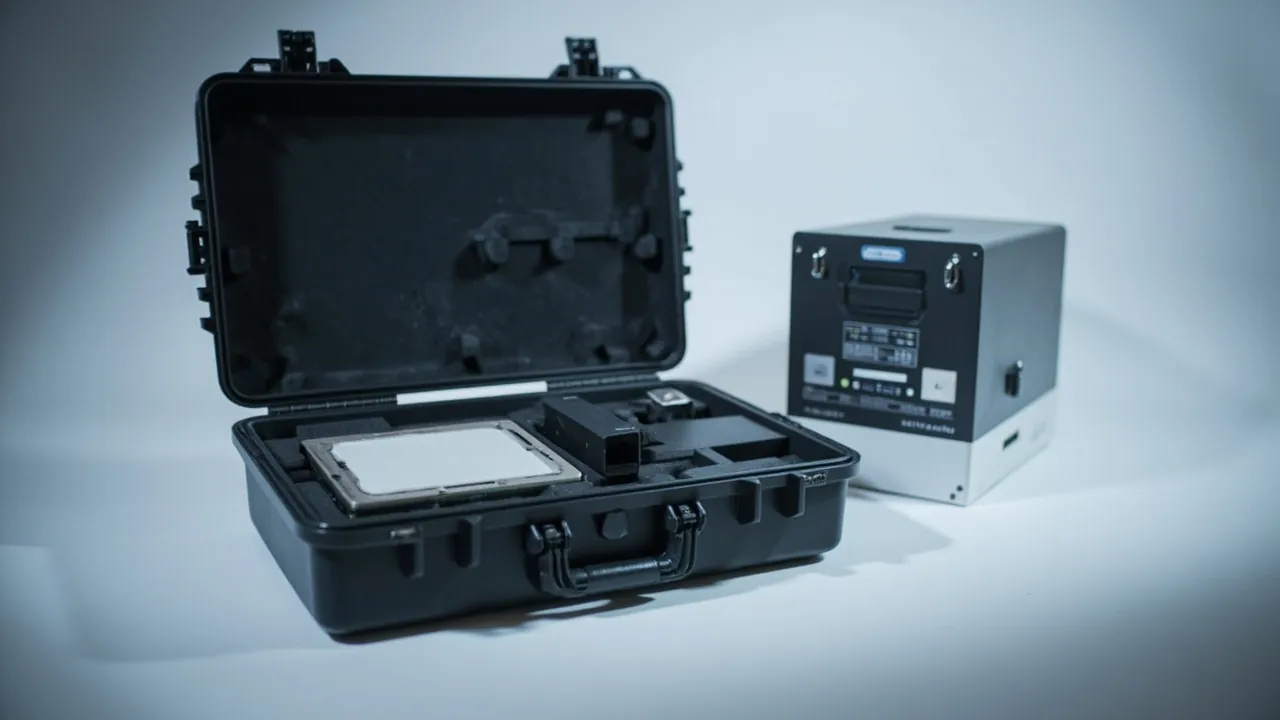
A chip packaging equipment case is not a container that simply holds a die-bonder head or an interconnect assembly. Its actual job is to deliver a component that has already been calibrated to sub-micron tolerance together with its cleanliness state, its locating datums, and its electrostatic integrity fully intact. Downtime in a packaging line is measured in minutes, and a case that was never engineered for contamination control can force a full recalibration of placement accuracy, dispense volume, and bond position the moment the part is installed. The conclusion is unambiguous: packaging for die-attach and interconnect components must satisfy three conditions at once — controlled micro-vibration, controlled particle generation, and controlled static charge. Meeting only one or two of them does not work.
What makes these components difficult is that defects appear late. A single drop during transit may leave a displacement in a placement head that is far too small to see. The tool then runs normally for tens of thousands of units until placement offset starts drifting across a batch, or until corner joints begin failing intermittently, and only then does anyone trace the problem back to the transport leg. This article works through the failure modes of placement heads, feed mechanisms, and interconnect modules, and sets out an executable program covering cleanliness mapping, insert compartment design, micro-vibration control, test verification, and receiving inspection. It is written for equipment engineers at packaging houses, dealers in refurbished semiconductor tools, and purchasing staff at original equipment builders.
Table of Contents
- Why a Component Case in a Packaging Fab Is Really a Cleanliness System
- Component Inventory and Contamination Sensitivity Grading
- Mapping Cleanliness: Translating ISO 14644 Classes to the Inside of a Case
- Placement Heads and Dispense Units: How Sub-Micron Accuracy Fails
- Feed and Transfer Mechanisms: Deflection, Static, and Fretting
- ESD Control: Applying ANSI/ESD S20.20 to Packaging Practice
- Compartmented Insert Design: Datums, Locating Features, and Access Paths
- Micro-Vibration Control: Deriving Cushion Design From an Allowable Limit
- Low-Particle and Low-Outgassing Requirements for Packaging Materials
- Sealing and Pressure Equalization: Managing Air Exchange in a Clean Case
- Unpacking Discipline Inside the Cleanroom and Case Reuse
- Verification: Combining ISTA, MIL-STD-810H, and Cleanliness Re-Test
- Shipping Documents, Marking, and Acceptance Criteria
- Frequently Asked Questions
- Conclusion and Related Reading
Why a Component Case in a Packaging Fab Is Really a Cleanliness System
In general machinery, packaging means keeping cargo from being damaged in transit. Inside a semiconductor packaging fab that definition is insufficient. Contamination picked up by equipment components during transport becomes a particle source the moment those components re-enter the cleanroom.
Consider a concrete case. A die-bonder placement head ships from a supplier to a packaging plant wrapped in an ordinary wooden crate with bubble wrap. The crate sheds splinters during handling. The bubble wrap releases plastic fragments as it rubs against itself. Inside the crate there are paper labels, adhesive tape, and corrugated cardboard pads. Nothing about this packaging looks wrong to a logistics inspector, yet it delivers a heavy load of fibrous and adhesive-bearing particles to the cleanroom pass-through window. If the fab operates at ISO 14644-1 Class 6, the act of opening the crate alone can create a local particulate concentration far above the class limit.
That is why the first-order requirement for a component case is that the packaging materials and the interior surfaces must themselves be a low-shedding surface, not a medium that releases contamination into a controlled environment. This single requirement determines insert materials, label format, sealing method, and the unpacking procedure, and it rules out the practice of grabbing whatever crate is nearby.
The second requirement is micro-vibration. Placement accuracy, dispense volume, and bond position all rest on the mechanical datums of the tool. Sustained vibration in transit causes micro-motion inside adjustable mechanisms, particularly units containing preloaded springs, ball rails, or piezoelectric actuators. The third is static charge. The gate-oxide breakdown threshold of CMOS devices is low, and packaging equipment is full of engineering plastics, belts, idler wheels, and cabling, which are precisely the places where static charge is generated and accumulated. For the broader framework, see how ESD shielding cases are built and selected; this article focuses only on how that framework lands on semiconductor component packaging.
Component Inventory and Contamination Sensitivity Grading
Before anything is packed, build a table listing each subsystem, its material, and its sensitivities. Packaging equipment parts range from nozzles weighing a few tens of grams to gantry modules weighing over a hundred kilograms, and applying one cushioning logic to all of them guarantees a mistake.
| Process Station | Build Materials | Particle Limit Class | Charge Control Need | Impact Tolerance | Vibration Tolerance | Dominant Delivery Defect |
|---|---|---|---|---|---|---|
| --- | --- | --- | --- | --- | --- | --- |
| Die placement head, nozzle shaft | Aluminum alloy, ceramic, miniature bearings | High | Medium | High | Very high | Nozzle concentricity shift, vacuum leak-down |
| Dispense valve, metering pump | Stainless steel, piezo ceramic, seals | Very high | Low | High | High | Shot-volume drift, spool sticking, crystallized residue |
| Vision camera, ring illumination | Optical glass, CMOS sensor | Very high | High | Medium | Very high | Optical axis shift, gray-level drift |
| Tape feeder, index sprocket | Engineering plastic, spring steel | Medium | Very high | Low | Medium | Misindexing, sprocket tooth breakage, charged devices |
| Leadframe transfer track | Cemented carbide, stainless steel | High | Low | Medium | High | Scored track face, parallelism excursion |
| Interconnect and bonding stage | Copper alloy, ceramic heater | High | Low | High | High | Warped heated face, uneven temperature profile |
| Gantry XY stage, linear motor | Granite, rare-earth magnet | Medium | Low | Very high | Very high | Magnet weakening, air-gap shift, accuracy loss |
| Harness and connectors | Copper, fluoropolymer, connector bodies | Medium | High | Low | Medium | Deformed pins, breached shield layer |
The engineering rule for using this table is to take the strictest row, not the average. If a single very-high-sensitivity component shares a case with anything else, the whole case is designed to that component's vibration and cleanliness limits. A common error is putting a vision camera and a heavy rail in the same cavity; the cushioning is then stiffened to carry the rail's weight, and the camera absorbs an acceleration well beyond what it can take.
A second practical rule is tiered packing. Group components with similar sensitivity into the same case rather than filling cases with whatever fits. One placement head, one dispense valve, and two spare nozzles make a sensible case. One placement head plus a dozen rail counterweights almost always sacrifices the placement head. Tiered packing increases the case count, but it lowers per-item risk substantially and makes it easier to dispatch different cases to different lines against a work order.
Mapping Cleanliness: Translating ISO 14644 Classes to the Inside of a Case
A cleanroom class is a spatial metric while a case is a closed container, so the two need a mapping logic. The usual approach is to work backward from a single criterion: the moment of opening must not push the local environment out of class.
Start by fixing the target environment. Packaging fabs commonly run at ISO 14644-1 Class 5 through Class 7, with particle sizes of interest typically at the 0.3 µm and 0.5 µm thresholds. If the case is opened outside the cleanroom, it must act as a barrier. If it is opened at a pass-through or in an airlock, it must satisfy two conditions: low shedding and easy wiping.
| Target Environment Class | Opening Location | Exterior Requirement | Interior Surface Requirement | Recommended Sealing Method |
|---|---|---|---|---|
| --- | --- | --- | --- | --- |
| Class 5 | Inside airlock | Non-shedding exterior, IPA-wipeable | No fiber release, no exposed adhesive | Double bag plus rigid case, offset seals |
| Class 6 | Pass-through window | Clean exterior, no paper labels | Dense, non-porous insert, no outgassing | Single cleanroom bag plus rigid case |
| Class 7 | Fab buffer zone | Standard clean exterior | Wipeable insert | Cleanroom bag plus rigid case |
| Uncontrolled | Ordinary warehouse | Dust and moisture protection | Dense insert, no shedding | Sealed rigid case with desiccant |
The rightmost column's double-bag-plus-rigid-case arrangement is standard practice for a Class 5 environment. The rigid case provides mechanical and micro-vibration protection, while the inner cleanroom bag provides the particle and static barrier. The two seals are offset so that after the outer bag is stripped inside the airlock, the inner bag surface is still clean. This strip-to-enter approach markedly reduces the particle burst at the moment of opening.
One caveat deserves emphasis: packaging cannot substitute for a cleanroom. Its role is to preserve component cleanliness across the transport chain and to avoid introducing new contamination sources during the transition into a controlled environment. Where a fab has a formal cleanliness verification requirement, the purchase agreement can call for wipe sampling or particle-count records from the interior surfaces. When JUNZHJIA handles orders of this type, insert materials and cleanroom bag combinations are selected against the customer's specified class, and supporting material documentation is provided.
Placement Heads and Dispense Units: How Sub-Micron Accuracy Fails
The placement head is one of the most precision-dense components on a packaging tool. Internally it carries a Z-axis drive, a rotational alignment mechanism, vacuum passages, a pressure sensor, and one or more nozzle seats. What unites them is that they depend on relative positions calibrated at the factory, maintained by preload, interference fit, or locking screws.
The first class of transport damage is sliding at a locking interface. A single vibration event of modest amplitude but long duration can rotate a fastener that has no anti-rotation treatment, shifting nozzle-seat concentricity away from the calibrated value. The shift is invisible during idle operation but shows up as a lower pick rate and placement offset when the tool handles 0201 packages or smaller.
The second class is indentation in miniature bearings and rails. Z-axis guidance usually relies on miniature linear rails or crossed-roller rails. Indentation on a raceway converts into periodic resistance fluctuation during motion, which finally appears as degraded placement-height consistency.
The third class hides in vacuum and pneumatic circuits. Dust, packaging debris, and particles from a ruptured desiccant pack can all enter vacuum passages or gas sealing faces. Once a particle lodges on a nozzle sealing face, vacuum leakage causes a picked device to drop off during a high-speed move.
Three countermeasures follow. First, treat the placement head as its own dedicated case and never mix it with other components. Second, restrict axial and rotational freedom, using insert locating faces that bear against the nozzle-seat outer diameter or a flange datum rather than relying on spring pressure. Third, cap every pneumatic port with a cleanroom plug made of low-shedding elastomer, never a fibrous cotton plug. Dispense units carry an additional requirement: if medium remains inside the valve, temperature and humidity cycling in transit can crystallize or cure it, so follow the supplier's flushing procedure before dispatch and place a visible humidity indicator card in the case.
Feed and Transfer Mechanisms: Deflection, Static, and Fretting
For feed mechanisms, contamination and static risk typically deserve more attention than mechanical risk. Tape feeders, reel carriers, and leadframe transfer rails are structurally simple and adequately stiff, so they rarely deform in transit. But they carry two hidden problems.
The first is static accumulation. Feed paths use a great deal of engineering-plastic gearing, belting, and idler wheels, all of which charge readily under friction. If the insert also uses untreated polyurethane or polyethylene foam, friction charging creates a locally high potential that forms a discharge path to nearby static-sensitive devices during unpacking. The correct approach is to introduce a conductive or dissipative layer into the insert and give that layer a bleed path to the case's grounding structure. Following the logic of ANSI/ESD S20.20, surface resistance of work surfaces and packaging materials should fall within the dissipative band, and insulating materials should not contact device leads or carrier tape directly.
The second is fretting wear. Ratchets, one-way bearings, and spring leaves inside a feeder are sensitive to sustained low-amplitude vibration. Over time, contact surfaces develop fretting, which first appears as unstable feed timing and later as jamming. The remedy is not a stiffer case. It is a damping layer between the insert and the component that converts vibration energy into heat rather than absorbing it through rigid collision. General practice for damping and cushion layer design is covered in the custom insert design workflow.
There is also a packing detail specific to feed components: tape index wheels and reels must be clamped along their own axis, not merely held against a case wall. With side restraint only, vertical shock in transit makes the reel bounce, the carrier tape unwinds under inertia, and reloading requires manual rethreading — a direct hit to line recovery time.
ESD Control: Applying ANSI/ESD S20.20 to Packaging Practice
ESD control in the semiconductor industry already has a mature framework, and ANSI/ESD S20.20 is the procedural standard most widely adopted within it. It does not dictate case construction directly, but it specifies the properties packaging materials must exhibit and the management requirements at the point of use. Reduced to component cases, four points matter.
Point one: material zoning. Surfaces that may contact a device or its leads should use dissipative or conductive materials. Surfaces used only for structural support with no device contact may use low-shedding insulating materials. Point two: a grounding path. If the case uses a conductive shell, provide an explicit bonding point so it can be tied to the grounding bus inside the cleanroom. Contact resistance at that bonding point must be controlled. Point three: traceable marking. Static-sensitive component cases need clear ESD-susceptibility and packaging-material classification marking, and the marking must not use paper that sheds fiber. Point four: opening environment. Static-sensitive components should be unpacked in an area with ESD protection in place. Packaging reduces risk; it does not replace wrist straps, bench mats, and ionizers.
One frequently overlooked detail is performance decay of packaging materials after repeated trips. Over long service, contamination and abrasion can shift the surface resistance of a dissipative material out of its target band. Where a component case is reused on a returnable basis, the acceptance specification should include periodic re-testing rather than a one-time qualification. General acceptance sampling practice is described in custom case AQL acceptance practice.
Compartmented Insert Design: Datums, Locating Features, and Access Paths
The insert is the technical core of the case. Its function is not to fill empty space but to hold the component at a determined position in space using the minimum number of constraint points. Follow this sequence.
Step one, establish the locating datum. Most semiconductor equipment components have a machined face or a mounting flange. Prefer those as datums over complex housing contours. The datum determines the component's attitude in the case and therefore the load path.
Step two, determine which degrees of freedom to constrain. The goal is to restrain all six, but the method differs by direction: vertical support carries weight, lateral ribs provide horizontal restraint, and axial end stops limit endplay. Avoid wrapping everything in soft foam and compressing it, because soft foam compacts under vibration and loses its restraint.
Step three, plan the access path. A cavity must leave room for fingers or a fixture. A cavity that is too narrow forces the operator to pry the component out, and prying is itself a high-risk local shock event. A practical solution is a relief notch or a lead-in chamfer on a cavity sidewall.
Step four, handle the accessories. Screws, washers, plugs, and tools each need their own cavity and must never share one with a precision component. A single loose M3 screw migrating in a case under vibration will produce continuous scoring on a component surface.
Insert material selection depends directly on component weight, cleanliness requirement, and trip count. A common combination is a structural support layer in EVA or cross-linked polyethylene with a low-shedding closed-cell contact layer, and a cleanroom wiper facing where needed. For very high precision components sensitive to outgassing, the contact layer may need cleanroom-grade silicone or cleanroom polyurethane. Broader material comparisons and cleanliness compatibility are covered in how to compare insert foam materials.
Micro-Vibration Control: Deriving Cushion Design From an Allowable Limit
The most common cushioning error is choosing thickness by feel. The correct approach runs in reverse: establish the component's allowable acceleration first, then use the expected transport acceleration spectrum to calculate the required cushion stiffness and thickness.
| Component Type | Cushioning Tendency | Allowable Shock Band | Pulse Width Band | Design Notes |
|---|---|---|---|---|
| --- | --- | --- | --- | --- |
| Placement head, dispense valve | Medium rate, all axes | 20 G – 35 G | 6 ms – 11 ms | Restrict rotational freedom |
| Vision camera, optical module | Very low rate, free suspension | 10 G – 20 G | 6 ms – 11 ms | Assess the optical axis on its own |
| Gantry XY stage, linear motor | Low rate, face bearing | 15 G – 25 G | 6 ms – 11 ms | Protect magnets from hard blows |
| Tape feeder, transfer track | Medium rate | 30 G – 50 G | 6 ms – 11 ms | Static control outranks shock control here |
| Harness, connectors | Tied to the host | Not applicable | — | Tie down so they cannot whip |
These allowable values are engineering ranges, not standard-mandated figures. Where the tool supplier publishes a shock or vibration ceiling, that figure governs the design, and only a physical package test can confirm the outcome. Where the maker provides no limit, set a conservative value on the principle that higher precision demands more margin, then verify it in first-article testing.
The derivation runs in three stages. First, define the input. Establish the transport mode (road, air, sea) and the expected drop height; road transport levels can follow the appropriate ISTA test procedure. Second, use the cushion curve. With component weight and allowable acceleration known, find the corresponding static stress on the material supplier's cushion curve to obtain the required bearing area and thickness. Third, check multi-axis behavior. Vertical cushioning cannot be copied to horizontal directions, because contact area, support arrangement, and restraint method all differ.
Two quantities are easily missed. The first is resonance. If the natural frequency of the cushioning system falls inside the excitation band of transport vibration, the system amplifies rather than attenuates. As a rule, keep the package's natural frequency below the dominant transport excitation, or use a damping layer to lower the resonant peak. The second is stacking load. If the case is stacked in transit, the weight above continuously pre-compresses the cushion, reducing its load capacity. Stack height must be fixed at the design stage and included in the calculation. For sealing behavior as internal pressure changes with altitude, see how a pressure equalization valve works.
Low-Particle and Low-Outgassing Requirements for Packaging Materials
Packaging materials entering a controlled environment must address two contamination categories: particle release and chemical outgassing.
Particle release comes from fibers and fillers shedding from material surfaces, and from material fracture in use. Monolithic closed-cell foam is generally preferable to cut open-cell foam, because the cut face of open-cell material exposes a large porous structure that releases debris under friction. Textile materials also generate fiber under repeated rubbing, including the edges of ordinary cleanroom wipers, so contact surfaces should use continuous, fiber-free materials or fabrics with sealed edges.
Chemical outgassing is more insidious. Residual blowing agents, plasticizers, or flame retardants in some foams release slowly inside a sealed case and deposit a hazy film on optical surfaces or sensor windows through gas-phase deposition. On optical modules this is particularly damaging, because gray-level drift is often only noticed when process parameters visibly deviate. Countermeasures include selecting low-volatility formulations, aging foam with adequate ventilation before packing, and avoiding solvent-based labels and tapes inside the case.
Metal components add a further tension between cleanliness and corrosion protection. Anti-rust oil can itself become a chemical contamination source in a cleanroom, so steel parts destined for semiconductor components should prefer oil-free protection such as vapor-phase corrosion inhibitor film, desiccant with a low-humidity seal, or surface passivation. Where a rust preventive is genuinely necessary, its volatility characteristics must be evaluated together with the cleanliness class.
Sealing and Pressure Equalization: Managing Air Exchange in a Clean Case
Sealing and venting are a genuine contradiction in clean packaging. A fully sealed case blocks external particles and moisture, but pressure and temperature changes in transit create a differential across the wall. If the case is truly airtight, that differential deforms the seal, distorts the case, and can even disrupt the locating relationships inside the insert.
Three common approaches each suit different situations.
| Approach | Construction | Advantage | Limitation | Suitable For |
|---|---|---|---|---|
| --- | --- | --- | --- | --- |
| Fully sealed | High-grade gasket, no vent path | Strongest moisture and contamination barrier | Must withstand differential, slow vent before opening | Short routes, clean transfers |
| Pressure equalization valve | Gasket plus hydrophobic membrane valve | Automatic differential balance, blocks liquid water and particles | Membrane integrity needs periodic inspection | Air freight, cross-climate shipping |
| Inner cleanroom bag | Rigid case plus independently sealed inner bag | Separates cleanliness barrier from mechanical protection | Extra material and handling steps | Class 5 and Class 6 delivery |
The core of a pressure equalization valve is a hydrophobic breathable membrane. It passes gas while blocking liquid water and most particles. Membrane pore size must match the component's cleanliness class: if the component is sensitive to sub-micron particles, a general-purpose filter membrane may not maintain internal cleanliness, and the better answer is to use a cleanroom bag as the inner barrier while the rigid case handles mechanical and pressure management. The same principle runs through keeping cleanroom-rated equipment components clean in transit.
Desiccant selection must also match cleanliness requirements. Ordinary silica gel can release dust once saturated, so use desiccant enclosed in a breathable cleanroom bag and avoid exposing loose granules to the case interior. Dosage follows from the enclosed volume, the length of the journey, and the humidity target, not from habit.
Unpacking Discipline Inside the Cleanroom and Case Reuse
However good the packaging, a failure at the opening step undoes all of it. The unpacking sequence should be written as a work instruction containing at least the following.
- Confirm the opening location. State explicitly whether opening occurs in an airlock, at a pass-through, or in a buffer zone, and verify it matches the assumption used in the packaging design.
- Treat the exterior first. Wipe the case exterior with a material compatible with the cleanliness class so external contamination is not carried inside.
- Strip in layers. For a double-bag configuration, strip the outer bag at a designated point and collect it separately; never shake it inside a clean zone.
- Transfer the inner layer. Move the inner cleanroom bag and the component into the clean zone together, and open the inner bag there.
- Separate insert from component. Keep the motion smooth to avoid generating particles from friction between insert and component.
- Control the exit path. The exit path for empty cases and inserts must not cross the entry path of the component, to prevent secondary contamination.
Reuse requires an explicit decision. Returnable case bodies may be reused when the structure is undamaged, the gasket is intact, the insert shows no permanent compression set, no visible contamination is present, and wiping or cleaning brings it back to cleanliness requirements. Contact-layer inserts generally should not be reused long term, because cleanroom contact materials accumulate surface contamination over repeated use and cleaning can alter their surface characteristics. Where cost pressure exists, a hybrid model works well: reuse the rigid case and replace the insert on a defined cycle, with that cycle written into the contract.
One reuse-related detail deserves mention: on each return, inspect the case for foreign objects, gasket aging, latch deformation, and marking integrity. Skipping this step makes reliability decay quickly with trip count. For overall service-life assessment, see how many trips a protective case can take.
Verification: Combining ISTA, MIL-STD-810H, and Cleanliness Re-Test
Component case verification usually has three parts: mechanical, environmental, and cleanliness. They serve different purposes and cannot substitute for one another.
Mechanical testing verifies the packaging's ability to protect the contents. Common references include the ISTA series of transport test procedures, which cover drop, vibration, compression, and concentrated impact, and the GB/T 4857 series. ISTA's strength is that it is layered by real transport mode, which suits export programs; GB/T 4857 is widely used across domestic supply chains and third-party laboratories. The two can be combined: run ISTA as the programmatic verification, then supplement with GB/T 4857 items. The selection logic is explained in how to choose a transport test procedure.
Environmental testing verifies stability under temperature, humidity, and low pressure. The corresponding method clauses of MIL-STD-810H provide the profile framework for high temperature, low temperature, humidity cycling, vibration, and shock. The scope of that reference deserves stating plainly: MIL-STD-810H supplies test methods only, and citing it confers no military certification on a product. A packaging product claiming military compliance should be supported by an actual test report, not merely by citing a standard number.
Cleanliness re-test is the step most often skipped. For semiconductor component cases, take wipe samples or run particle counts on interior faces once mechanical and environmental testing is complete, confirming the test caused no insert shedding or outgassing. A design should be rejected whenever the insert shows powdering, cracking, or lasting compression set after testing, even if the component itself survived the shock test, because the barrier function would no longer hold after a real shipment.
Sample size should match program scope. Development work often uses a single sample for screening; production qualification should use multiple samples against a sampling plan to cover different insert material lots. For high-value components, consider installing shock and temperature-humidity data loggers so that every real shipment also becomes a data collection opportunity. The loggers themselves must be secured and cushioned; they cannot be left loose inside the case.
Shipping Documents, Marking, and Acceptance Criteria
In the semiconductor industry, shipping documents and markings are not just logistics information. They are also part of cleanliness and static control.
On marking, include the component name and unique serial number, required cleanliness class, ESD susceptibility marking, orientation markings (this side up, do not tilt, maximum stack height), the required opening location, and the reuse status of the packaging. Marking materials should be non-shedding synthetic labels or in-mold printing; paper labels that must be peeled inside a clean zone should be avoided.
On documents, include at minimum a packing list, a record confirming component appearance and cleanliness state, insert material documentation, desiccant placement record and expiry, and the reference numbers of applicable packaging test reports. For repair round-trip scenarios, include the data-logger record from the previous shipment where available, so vibration exposure can be compared.
On acceptance, split the decision into case condition and component condition. Case condition covers the shell, gasket, latches, insert, and marking. Component condition covers appearance, cleanliness, ESD test points, and sampling of critical dimensions or function. Sampling items and acceptance limits belong in the purchase agreement, along with a defined disposition path for non-conformance. For volume supply, the sampling plan can follow general industrial practice combined with the methods described in custom case acceptance and sampling.
When JUNZHJIA takes on semiconductor equipment packaging programs, the usual route is to model and prototype the insert against the customer's component drawings and cleanliness class, then select the case body, sealing, and static-control configuration to match the transport mode, and finally lock the critical parameters into drawings and acceptance documents so that later batches stay consistent. OEM and ODM supply and global delivery can be scheduled to the program's own cadence.
Frequently Asked Questions
Q: In one sentence, how does a chip packaging equipment case differ from an ordinary equipment case?
A: The difference is in what the case is designed to control. An ordinary equipment case mainly controls mechanical damage, so its design centers on shock, vibration, moisture, and corrosion. A chip packaging equipment case must additionally control cleanliness and static charge. On cleanliness, the packaging materials themselves must be low-shedding and low-outgassing, contact surfaces must be fiber-free, labels cannot be paper, and no loose filler that generates debris is permitted inside. On static, any surface that may contact a device must use dissipative or conductive material and a bonding point must be provided. These three dimensions are additive rather than parallel: if any one fails, the investment in the other two is wasted. The most common real-world failure is excellent mechanical protection combined with ordinary open-cell foam, which releases a large particle burst when opened in the cleanroom and forces the component through an unplanned reclean, increasing rather than reducing risk. When selecting a design, confirm the target cleanliness class and ESD requirements first, then return to the mechanical design.
Q: ISO 14644 classes describe a space, so how do they guide packaging design?
A: Work backward from the criterion that the moment of opening must not push the local environment out of class. First fix the opening location. If the component is opened under Class 5 or Class 6 conditions, the packaging must not cause an obvious contamination event at the point where it is stripped. Three requirements follow: the case exterior must be wipeable without linting before it enters the controlled area; no material inside may release particles continuously; and the opening action itself must not generate friction debris. In practice this leads to a rigid case plus double cleanroom bag configuration, where the rigid case handles mechanical and moisture protection and the bags handle the particle barrier, with seals offset so the inner bag surface remains clean after the outer bag is stripped in the airlock. Packaging still cannot replace a cleanroom. Its role is to maintain the component's clean state across the transport chain and to avoid introducing new contamination sources in the transition. Where the fab has a formal verification requirement, write wipe sampling or particle counting records for the case interior into the agreement.
Q: What is the most common transport damage to a placement head, and why is it hard to detect?
A: The most common damage is micro-sliding at locking interfaces and raceway indentation in miniature rails. Both share the characteristic of extremely small displacement that is entirely invisible during a visual inspection. Locking-interface sliding occurs at preloaded screws or interference-fit faces; a single vibration event of modest amplitude but long duration is enough to rotate a fastener slightly, moving nozzle-seat concentricity away from the calibrated value. Raceway indentation occurs on the surface of the guidance rail and converts into periodic resistance fluctuation during motion. Neither is caught early because the tool usually still runs in the first weeks, with offset staying inside process tolerance. The problem only surfaces when the tool handles smaller packages or runs at a higher rate, appearing as a lower pick rate, placement offset, or degraded height consistency. The countermeasure is to restrict axial and rotational freedom in the packaging design, bear against a flange datum rather than relying on spring pressure, and record factory calibration data in the delivery documentation so it can be compared before installation.
Q: What does ANSI/ESD S20.20 actually require of packaging materials?
A: The standard's core purpose is to establish an electrostatic discharge control program, and its packaging requirements fall into three layers: material properties, grounding path, and use management. On material properties, parts that contact static-sensitive devices directly should use dissipative or conductive material with surface resistance in the dissipative band, avoiding untreated insulating foam. On grounding, a conductive shell should have an explicit bonding point for connection to the cleanroom grounding bus, with controlled contact resistance. On management, the standard requires clear ESD marking, a defined sensitivity classification, and unpacking in an area with protective measures in place. One point is easily missed: dissipative material performance decays over time, and surface contamination plus abrasion can shift surface resistance out of the target band. Where returnable reuse is planned, the acceptance specification should therefore include periodic re-testing rather than a single qualification.
Q: Why should cleanroom packaging avoid paper labels and ordinary bubble wrap?
A: Because both are continuous particle sources. Paper consists of fiber, and peeling it releases large quantities of fibrous debris, which is a classic foreign contaminant in a clean zone. Fiber also behaves more unpredictably than spherical particles in terms of settling and re-entrainment, making it harder for laminar flow to remove. Ordinary bubble wrap has two issues: most consumer-grade product uses polyethylene without cleanroom processing, so the surface may retain processing aids, and the film releases plastic fragments under friction. Once a bubble ruptures, it also sheds debris. Inside a closed case these particles recirculate with air movement and eventually deposit on component surfaces or enter pneumatic circuits. Alternatives include in-mold printing or synthetic labels, cleanroom-grade bag film, and monolithic closed-cell insert materials. Where cushioning sheet is genuinely needed, specify a cleanroom-grade foam with sealed edges so no open-cell cross-section is exposed.
Q: Why can cushion thickness not be set by rule of thumb?
A: Because cushion effectiveness depends on matching the material to component weight and allowable acceleration, not on thickness alone. Every foam has a cushion curve describing the peak acceleration transmitted to the contents at a given static stress. A material that is too soft fully compacts under the load and passes shock straight through; one that is too hard barely deforms and also fails to attenuate; only in the correct static stress band is cushioning efficiency per unit thickness at its highest. The engineering method is to obtain the allowable acceleration, read the required bearing area and thickness off the cushion curve, then check natural frequency and stacking load. Resonance matters especially: if the natural frequency of the packaging system falls inside the dominant transport vibration band, the cushion amplifies the response instead of attenuating it. This is also why the same insert can perform noticeably worse when moved to a heavier component.
Q: Can component cases be reused inside the cleanroom?
A: Distinguish between the case body and the contact-layer insert. A rigid case body can be reused when the structure is undamaged, the gasket is intact, the latches are not deformed, and wiping or cleaning brings the surface back to cleanliness requirements, and reuse economics are substantial. Contact-layer inserts generally should not be reused long term, because cleanroom contact materials accumulate surface contamination over repeated use and cleaning itself can alter surface characteristics, for example by shifting dissipative performance or creating microcracks in a closed-cell surface that then become a new particle source. A practical model is to reuse the rigid case while replacing the insert on a defined cycle, with the cycle and acceptance criteria written into the purchase contract. Under either model, inspect each returning case for foreign objects, gasket aging, insert compression set, and marking integrity. Skipping this makes packaging reliability decay quickly with trip count.
Q: What role does MIL-STD-810H play in verifying semiconductor component cases?
A: Its role is to supply the test methodology and profile design basis for environmental testing, covering procedures and severity-setting methods for high temperature, low temperature, temperature shock, humidity, vibration, mechanical shock, and low pressure. For cases that must cross climate zones or experience low pressure during air freight, designing the verification profile against the relevant methods in that standard is more rigorous than inventing test conditions, and it is more readily accepted by customers and third-party laboratories. It must be stated clearly that MIL-STD-810H is used here only as an environmental test method reference and does not indicate that the packaging product or packaging design has obtained any military certification. Market claims of military-grade packaging without an accompanying test report should not be treated as technical evidence. For semiconductor components, environmental testing should be followed by a cleanliness re-test to confirm the testing did not cause insert powdering or outgassing; otherwise the design should be rejected even if the component came through the shock test unscathed.
Q: What information should be supplied to a supplier when specifying a custom chip packaging equipment case?
A: The more complete the input, the fewer prototype iterations are needed. Provide the following: a 3D model or accurate outline drawing of the component with the machined faces or flanges that can serve as locating datums marked; component weight and center of gravity; allowable shock and vibration limits from the equipment maker, or an explanation of the basis used if none exist; target cleanliness class and ESD control requirements; transport mode and expected route, including whether air freight or sea freight is involved and whether multiple transfers occur; opening location and cleanroom operating conditions; whether the case must be returnable and the expected trip count; and the acceptance method and document types required. If the component is sensitive to chemical outgassing, state the material categories that are prohibited. JUNZHJIA typically uses this input to model the insert and run a trial fit, then matches the transport mode to determine case structure, sealing method, and static-control configuration, and locks the critical parameters into drawings and acceptance documents to keep later batches consistent.
Conclusion and Related Reading
The technical difficulty of a chip packaging equipment case is not in the case itself but in the fact that it carries three responsibilities at once: mechanical protection, a cleanliness barrier, and static control. Real trade-offs exist between them. A tighter seal makes pressure differential more of a problem. A denser material raises processing difficulty and cost. Stronger restraint makes the component harder to remove. The professional approach is to make those trade-offs explicit: state the component's allowable limits, target cleanliness class, and transport route, then make design choices that can be verified and lock the conclusions down with test data and acceptance documents. For a packaging fab, the unplanned downtime avoided by a properly designed component case typically far exceeds its purchase price. For equipment builders and dealers, reliable packaging is part of delivery quality and one of the most direct levers available for reducing overseas after-sales cost.
Related Reading