

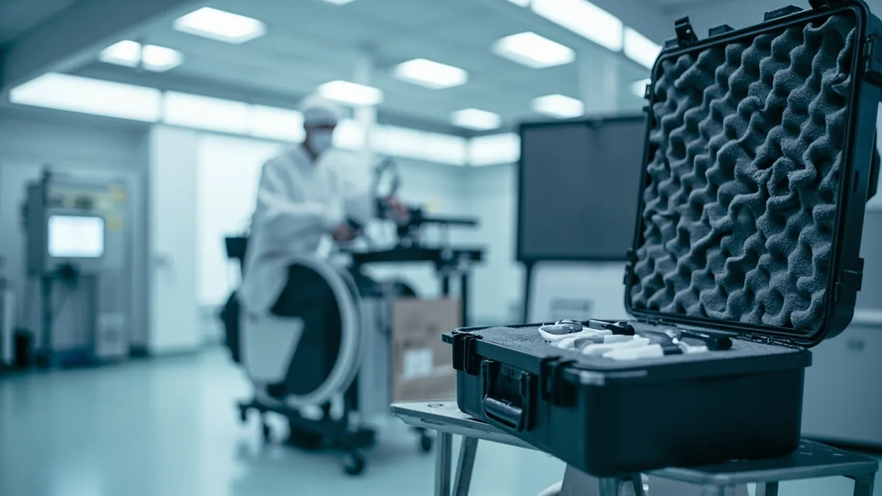
Cleanroom equipment and filter cases protect an unusual category of asset. A high-efficiency filter has almost no margin for damage: once the media is perforated or the gasket is deformed, the filter is scrap. And once a cleanroom instrument is shaken or contaminated, its readings are no longer credible. The answer is direct: protection for filters and cleanroom instruments requires contamination control and structural protection at the same time. The filter must travel from factory to installation without shedding a single out-of-limit particle or developing a single pinhole, and the instrument must arrive still able to pass calibration and leak testing.
Operational pain points in cleanrooms are consistent. Filters ship with packaging, but on site they get unwrapped early to save time, wrapped in plastic sheeting and pushed around on a trolley, or removed filters get stacked anywhere. On the instrument side, particle counters, anemometers, differential pressure transmitters and online monitoring probes travel between classified and unclassified areas in ordinary cases or cardboard boxes, with connectors exposed, sampling ports ingesting dust and the instrument bouncing in a vehicle.
Short distances at low classifications may hide the problem. In an ISO 14644 Class 5 area, or where EU GMP Annex 1 sterile processes apply, a single outcome of looking fine but failing leak testing triggers rework: filter replacement, repeat leak testing, repeat environmental monitoring and possibly a release schedule impact. If an instrument drifts, the validity of an entire monitoring data set has to be reassessed.
This article is written for cleanroom operations engineers, validation staff, filter suppliers and equipment buyers. It covers filter packaging layers, cleanliness classification matching, material compatibility, sealing class, vibration validation, cleaning strategy and acceptance traceability, with comparison tables and checklists. JUNZHJIA supplies custom inserts, OEM/ODM programmes and pocket sets matched to filter specifications for cleanroom equipment cases, and the structures described here come from that project experience.
Table of Contents
- 1. Why Cleanroom Equipment and Filters Need a Dedicated Protective Case
- 2. HEPA and ULPA Filter Construction and Weak Points
- 3. Filter Packaging Layers: Contamination Control from Factory to Installation
- 4. Cleanroom Instruments: Particle Counters, Anemometers and Pressure Gauges
- 5. Garments, Gloves and Consumables in Transfer
- 6. Matching Cleanliness Classification to Case Configuration
- 7. Material Compatibility: Low Shedding, Low Outgassing and Wipeability
- 8. Sealing Class: IP65/IP67 and Pressure Equalization Valves
- 9. Vibration and Transport Validation: ISTA, GB/T 4857 and Filter-Specific Criteria
- 10. Cleaning and Disinfection: Case and Insert Strategies
- 11. Custom Inserts: Pocket Design for Filters and Instruments
- 12. Acceptance and Traceability: AQL, Leak Test Records and Batch Management
- 13. Purchasing Decisions, Use and Maintenance
- Frequently Asked Questions
- Conclusion & Related Reading
1. Why Cleanroom Equipment and Filters Need a Dedicated Protective Case
A cleanroom depends on two classes of asset: equipment that maintains cleanliness, namely the high-efficiency filtration system, and instruments that prove cleanliness, namely the monitoring system. Their transport protection logic is entirely different from general industrial equipment.
First, a filter's integrity cannot be judged visually. HEPA and ULPA media are extremely fine glass fibre or PTFE membrane, with pleat spacing measured in millimetres. A single improper squeeze can create a micro-crack at a pleat root that is invisible to the eye, and such a defect only surfaces during post-installation scan leak testing. By then the filter is already installed, and replacement costs far more than the filter itself. Product standards such as the ISO 29463 series for high-efficiency filters, and the Chinese standards GB/T 13554 for HEPA filters and GB/T 6165 for HEPA filter test methods, define efficiency and leak test requirements, but none of that verification substitutes for physical protection during transport.
Second, instrument credibility depends on calibration state. Particle counters, anemometers, differential pressure gauges and microbial air samplers produce the readings used to classify a cleanroom. After vibration, an optical chamber can shift, a flow sensor can drift and a sampling pump can lose performance. These changes usually do not disable the instrument; they push readings to the edge of tolerance. Where classification is performed under the ISO 14644 series, that means the data cannot be cited. Cleanroom vacuum pumps and hydraulic actuators in pass boxes have lubricants whose cleanliness is commonly controlled against ISO 4406 contamination codes, so a leak or contamination event in transit also affects equipment condition.
Third, there is cross-contamination risk. A case moving repeatedly between classified and unclassified areas, without a clear clean-side and dirty-side discipline and without wipeable surfaces, becomes a contamination vector. Removed filters, spent consumables and maintenance tools can all carry external particulate into the cleanroom.
A direct test: if a problem with this item would require leak testing, metrological calibration or environmental monitoring to confirm, then its transport protection must be designed to be verifiable.
A cleanroom equipment and filter case must therefore deliver four capabilities at once: structural protection against compression and vibration, contamination control against dust and shedding with wipeable surfaces, sealing and environmental isolation through an IP class and pressure equalisation, and traceability covering batch, leak test record and calibration state.
2. HEPA and ULPA Filter Construction and Weak Points
Protection has to start from construction. A typical HEPA or ULPA filter comprises the following:
| Component | Function | Weak point | Main risk | Protection priority |
|---|---|---|---|---|
| --- | --- | --- | --- | --- |
| Media (glass fibre or PTFE) | Captures particles | Pleat roots, contact with separators | Micro-cracks, pinholes, fold damage | No squeezing, no point loading |
| Separators (aluminium foil or hot-melt) | Maintains pleat spacing | Contact face with media | Media abrasion under compression | Avoid lateral pressure |
| Frame (aluminium, galvanised or stainless) | Carries load and mounts | Corners, flange faces | Corner deformation, flange scoring | Corner protectors, flange isolation |
| Sealant | Seals media to frame | Bond line integrity | Cracking, debonding | Vibration and thermal shock control |
| Gasket (PU, silicone or EPDM) | Seals against the mounting frame | Compression state | Compression set, scoring | Never store under compression, independent support |
| Facing screen or grille | Protects media surface | Screen flatness | Denting presses into media | Surface isolation, no point pressure |
Four protection rules:
- Filters fear point loading more than anything. A single-point squeeze creates stress concentration at a pleat root, which is the most common origin of micro-cracks. Support must therefore be distributed area or line contact, and the filter must never rest against a sharp object, a bracket edge or a case corner.
- Gaskets fear long-term compression. The elasticity of a PU or silicone gasket depends on its shape. Prolonged compression produces compression set, the gasket no longer conforms after installation, and leak testing fails. Filters should therefore be packed so the gasket is not under compression, or at most under very slight compression.
- Frame corners are the most vulnerable feature. Aluminium frames are not especially strong, and a knocked corner deforms and prevents the filter seating against its frame. Pocket design should add local reinforcement at corners.
- Filters dislike humidity. Some media and sealants degrade in humid conditions, so the case should include a desiccant compartment, and a cold-stored filter should not be opened immediately in a warm humid production room.
Protection priorities also vary by construction:
| Filter type | Typical application | Construction | Priority difference |
|---|---|---|---|
| --- | --- | --- | --- |
| Separator-type HEPA | Standard terminal supply air | Aluminium foil separators, moderate strength | Focus on frame and flange protection |
| Minipleat HEPA | High-cleanliness supply air | Hot-melt separators, dense media | Focus on compression and moisture exclusion |
| ULPA | ISO Class 4 and above | Denser, more brittle media | Strictest no-contact protection throughout |
| V-bank or box filter | High airflow systems | Large, heavy | Focus on overall support and lifting interfaces |
| Cylindrical or cartridge | Process equipment, vacuum systems | Cylindrical form | Focus on radial compression and end cap protection |
3. Filter Packaging Layers: Contamination Control from Factory to Installation
A filter travels from manufacturer to warehouse to transport to site store to unpacking to installation. Protection cannot rest on one box; it has to be a layered, progressive system.
A recommended four-layer structure:
| Layer | Form | Function | Key requirement |
|---|---|---|---|
| --- | --- | --- | --- |
| First (inner) | Supplier packaging, bag or shrink film | Maintains cleanliness, excludes moisture | Never removed early; removal marks entry into the installation process |
| Second (cushioning) | Moulded insert, corner protectors, end cushioning | Resists vibration and shock | Distributed area contact, protected corners |
| Third (outer) | Protective case or rigid carton | Resists compression, dust and moisture | IP65 or better, reusable |
| Fourth (identification) | Labels, tamper seals, leak test record sleeve | Traceability and status management | Serial number, specification, leak test state, seal number |
On the question of unwrapping early, this is the most common management failure on site. The supplier packaging is part of the clean barrier, and once removed the filter is exposed to the handling environment. A clear rule should be established: unpacking happens in the cleanroom or the buffer room immediately before installation, and installation follows promptly. The case exists precisely so the filter stays behind an intact barrier until that moment, reducing risk in the last metre to a minimum.
On reuse, reusable cases are common in maintenance replacement. A cleaning and condition-confirmation process must therefore exist: empty, wipe, inspect the gasket, replace the insert where it is a consumable layer, apply a new tamper seal. Packing a new filter into a case still carrying particle residue achieves nothing.
On returning removed filters, a used filter may carry substantial particulate load and possibly biological contamination. Its transport must use dedicated cases and a dedicated process, never shared with new filters. Used-filter cases should be marked for contaminated items only, with a defined cleaning and disinfection procedure.
4. Cleanroom Instruments: Particle Counters, Anemometers and Pressure Gauges
Cleanroom monitoring instruments are the other high-value, high-precision asset class.
| Instrument | Critical components | Main risk | Protection priority |
|---|---|---|---|
| --- | --- | --- | --- |
| Airborne particle counter | Optical chamber, flow sensor, sampling pump | Optical misalignment, flow drift, pump shock | Vibration damping, fixed attitude, sealed sampling inlet |
| Online particle monitoring probe | Optical module, sampling tube port | Dust ingress at the port, optical path contamination | Port caps, separate tube packaging |
| Anemometer / flow hood | Hot-wire or vane sensor | Sensor deformation, hood distortion | Sensor isolation, hood compression protection |
| Differential pressure gauge / transmitter | Pressure sensor, pressure ports | Port blockage, overpressure damage | Port protection, axial fixing |
| Microbial air sampler | Sampling head, flow control | Head deformation, flow deviation | Dedicated pocket, soft bearing |
| Temperature and humidity logger / probe | Sensor element | Element contamination, calibration shift | Dedicated pocket, away from contamination |
| Calibration standards | Aerosol generators, flow standards | Loss of accuracy | High-grade damping, controlled temperature in transit |
Seven protection rules:
- Instruments must be fixed in attitude. Particle counters and transmitters have specified mounting attitudes and damping requirements for internal sensors and pumps. Transport them in the specified attitude and limit angular movement with the pocket.
- Sampling inlets and pressure ports must be capped. Once dust enters these openings it is hard to remove and can damage the internal optical path or sensor. Caps come off only at installation.
- Package tubing and cables separately. The bend radius of tubing and the shield integrity of cables both affect measurement, so coil them in dedicated pockets rather than compressing them against the instrument body.
- Prioritise damping over cushioning. Instruments contain optical and mechanical parts, and damping is worth more than pure cushioning. A layered insert with a rigid frame and a soft conforming layer raises damping effectively.
- Address static. Electronic modules are ESD-sensitive, so use an antistatic insert; see ESD shielding case design and application.
- Control humidity. Optical elements and electronics degrade with moisture, so provide a desiccant compartment.
- Keep calibration records with the instrument. The case should carry a copy of the calibration certificate and a pre and post transport condition record card so the effect of transport on calibration state can be judged.
One frequently overlooked issue is instrument storage inside the cleanroom. Where an instrument is stored long-term in a classified area, the case must be compatible with that environment: wipeable external surfaces, no particle release and no odour. Where the instrument moves in and out, follow the sequence strictly: wipe on the dirty side, transfer, open on the clean side.
5. Garments, Gloves and Consumables in Transfer
Beyond filters and instruments, cleanrooms consume garments, gloves, wipes, masks and shoe covers. These are low value but directly contribute to cleanliness, and the protection logic differs.
| Consumable | Main risk | Protection priority | Recommended approach |
|---|---|---|---|
| --- | --- | --- | --- |
| Cleanroom garments | Packaging damage, fibre release, moisture | Keep original packaging intact | Rigid case + burr-free liner + single-layer placement |
| Gloves | Packaging compression, static attraction of particles | Avoid compression, antistatic | Divided pockets + antistatic liner |
| Cleanroom wipes | Packaging damage, moisture absorption | Sealed against moisture | IP65 case + desiccant compartment |
| Masks and hoods | Compression distortion, packaging damage | Flat single-layer placement | Layer plates, no compression stacking |
| Sterile bags and packaging materials | Puncture, micro-cracks at folds | No sharp edges, no compression | Radiused liner + separate compartments |
Three core principles:
- The protection object for consumables is the packaging, not the item. As with single-use bioprocess components, damaged packaging means the item is unusable, so no protrusion, screw head or burr capable of puncturing packaging may exist inside the case.
- Avoid compression stacking. Compressed garments and masks take permanent creases that compromise fit and sealing, so place them in a single layer or separate with layer plates.
- Manage by expiry and batch. Consumables carry sterilisation expiry dates, so the case label area should be a replaceable label card supporting first-in-first-out by batch and expiry.
For cleanrooms shared with food or nutraceutical production, where a case also carries packaging materials, the GB 4806 series on food-contact materials is a useful reference for low-migration and low-odour assessment.
6. Matching Cleanliness Classification to Case Configuration
Cleanroom classification has two reference frameworks: ISO 14644-1 classes and the international GMP A/B/C/D grades. At the design level in China, GB 50457, the design standard for pharmaceutical industrial cleanroom facilities, is the important basis.
| Target area | Approximate ISO 14644-1 class | Typical use | Recommended case configuration | Key control point |
|---|---|---|---|---|
| --- | --- | --- | --- | --- |
| Grade A / B | ISO Class 5 | Aseptic core, filling zone | Fully sealed body + wipeable interior + sterile transfer bag | No fibre or particle release |
| Grade C | ISO Class 7 | Clean compounding, some dosage processes | IP65 or better + alcohol-wipeable liner + desiccant | Fully cleanable surfaces, no dead corners |
| Grade D | ISO Class 8 | Controlled non-sterile processes | IP54 to IP65 + moulded foam insert | Cleanable and traceable |
| ISO Class 4 and below (ULPA applications) | Higher classification | High-cleanliness processes | Fully sealed construction + fibre-free liner + multi-layer packaging | No-contact protection throughout |
| Unclassified (store, workshop) | Not applicable | Storage and maintenance | IP65/IP67 + corrosion-inhibiting liner | Must be cleaned and wiped before entering |
GB 50457 sets explicit requirements for material transfer between classified and unclassified zones, based on separation of material and personnel flow and preservation of pressure differential and cleanliness throughout transfer. The case acts as a mobile clean boundary; its external wipeability determines whether extra wrapping is needed and its sealing class determines whether external particulate enters during transfer.
On filter leak testing on site, ISO 14644-3 and GB/T 25915.3 provide the methods, with product-level reference to GB/T 13554 and GB/T 6165. These tests verify the installation, and the purpose of transport protection is to make leak testing pass the first time. Planning the transport protection scheme alongside the leak test plan at project stage is genuinely valuable.
Where EU GMP Annex 1 sterile processes apply, every material entering a Grade A or B zone needs a defined sterilisation or disinfection route. Filter cases are normally surface-disinfected in the anteroom before transfer, so the body material must withstand repeated wiping with isopropanol, hydrogen peroxide and quaternary ammonium compounds without cracking, blooming or plasticiser release.
7. Material Compatibility: Low Shedding, Low Outgassing and Wipeability
Cleanroom requirements on case and liner materials are far stricter than in general industry.
| Material | Advantages | Cleanroom considerations | Suitable class |
|---|---|---|---|
| --- | --- | --- | --- |
| PP (polypropylene) | Good chemical resistance, low water absorption, controllable cost | Large cases need ribs; deforms under prolonged heat | Grade C/D, store transfer |
| ABS | High stiffness, glossy wipeable surface | Sensitive to some solvents; long-term alcohol wiping needs validation | Grade C/D |
| HDPE | Good toughness, low-temperature performance | Marks easily; textured areas hard to clean | Unclassified |
| Glass-filled engineering plastic | High strength, dimensional stability | Confirm glass fibre is encapsulated and non-shedding | Grade C, precision instruments |
| Aluminium-magnesium alloy | High strength, anodisable | Needs corrosion treatment; avoid galvanic corrosion with stainless | Unclassified, heavy items |
| Closed-cell EVA foam | Low shedding, wipeable, customisable | Specify sulphur-free, chlorine-free, low-outgassing grades | Mainstream insert material |
| Open-cell PU foam | Soft and conforming | Sheds and absorbs moisture; use with caution | Generally not recommended |
Protecting stainless components matters equally. Cleanroom equipment uses large amounts of 316L whose corrosion resistance depends on an intact passive layer. Prolonged contact with chlorine-bearing materials, or a humid sealed environment, breaks the passive layer and starts pitting. Liner materials should therefore be sulphur-free, chlorine-free and low-outgassing, avoiding regrind foam. Provide a desiccant compartment, and separate components with non-woven fabric or clean-grade PE bags rather than ordinary VCI paper.
A note on vapour-phase corrosion inhibitors. Conventional VCI materials release inhibitors that can conflict with cleanroom expectations and product-contact compatibility, so they should be used cautiously in cleanroom applications. The more robust combination is closed-cell low-outgassing liner plus sealed case plus desiccant.
On flame retardancy, some cleanrooms and electronics facilities specify material fire performance, so a UL94 rating certificate can be requested. Note that UL94 reflects a material's burning characteristics and does not mean the assembled case holds a fire certification.
8. Sealing Class: IP65/IP67 and Pressure Equalization Valves
Sealing class is determined under IEC 60529 and the equivalent Chinese standard GB/T 4208.
| Class | Dust | Water definition | Typical cleanroom scenario | Notes |
|---|---|---|---|---|
| --- | --- | --- | --- | --- |
| IP54 | Limited dust protection | Splash resistant | Short transfer inside a store | Unsuitable near washdown areas |
| IP65 | Dust tight | Jet resistant from all directions | Most common for filters and instruments | Balances sealing and handling |
| IP67 | Dust tight | Short immersion, 1 m / 30 min | Cross-zone transport, wet loading, used filter returns | Pair with a pressure equalization valve |
| IP68 | Dust tight | Continuous immersion | Special requirements | High cost, rarely necessary |
The value of a pressure equalization valve is especially high in cleanroom applications, for three reasons. First, filter cases routinely experience temperature swings from warehouse to transport to site store to cleanroom, and the resulting differential makes the lid hard to open and deforms the gasket. Second, if the lid is opened quickly under a differential during cleanroom transfer, the airflow carries particulate from the external surface into the case, directly affecting environmental monitoring data. Third, the filter gasket itself suffers under prolonged compression, and additional compression caused by internal vacuum accelerates compression set. A pressure equalization valve uses a hydrophobic and oleophobic microporous membrane to breathe slowly while preserving IP65 or IP67. The principle and selection logic are in how the case pressure equalization valve works and how to select it.
A recommended six-step transfer sequence:
- Pack, close and seal the case in the unclassified area, applying the tamper seal and batch label.
- On the dirty side before the airlock or pass-through, wipe all six faces with a lint-free cloth and disinfectant.
- Allow the required disinfectant contact time.
- Move into the pass-through or airlock and apply a second disinfection step or UV exposure.
- Open on the clean side, slowly, equalising the pressure before lifting the lid to avoid turbulence.
- Remove the contents, then move the case out immediately or into a used-case holding area; never store it alongside clean materials.
Replaceability of seals and hinges matters for the same reason. The gasket is a wear item and replaceability determines case life; material comparisons are in protective case seal materials compared and structural detail is in toolbox hinge, latch and seal structure explained.
9. Vibration and Transport Validation: ISTA, GB/T 4857 and Filter-Specific Criteria
Validation criteria for filters and cleanroom instruments differ from general equipment cases: the question is not whether the case survived but whether the filter still passes leak testing and the instrument is still within calibration tolerance.
Three standards provide the basis:
- ISTA series. ISTA 1 for basic integrity, with ISTA 2 and 3 closer to real distribution. See ISTA transport testing procedure and case validation.
- GB/T 4857 series. Chinese basic test methods for transport packages covering vibration, impact, stacking and drop. See GB/T 4857 transport packaging testing for cases.
- MIL-STD-810H. Environmental test methods, of which Method 514 (vibration), 516 (shock), 507 (humidity) and 509 (salt fog) are commonly cited. Note that citing this standard is a reference to environmental test methodology and does not mean the product holds a military certification. See MIL-STD-810H environmental testing and case compliance explained.
Recommended filter and instrument validation criteria:
| Test item | Condition (typical) | Pass criterion | Inspection method |
|---|---|---|---|
| --- | --- | --- | --- |
| Corner drop | Per ISTA drop sequence, including corner, edge and face | No frame deformation, no corner denting | Visual plus dimensional measurement |
| Random vibration | Per ISTA or GB/T 4857 vibration profile | No gasket compression set, no visible media damage | Visual plus gasket thickness measurement |
| Stacking | Loaded to transport stacking height | No permanent frame deformation, no lateral compression marks | Visual plus dimensional measurement |
| Filter leak test | After test, per ISO 14644-3 / GB/T 25915.3 or product standard | Leak test passes, no out-of-limit leak points | Photometer scan test |
| Instrument function check | Power-on self-test after test | Self-test passes, zero and flow within tolerance | Instrument self-test plus flow standard |
| Instrument calibration check | Per calibration procedure after test | Deviation within supplier tolerance | Calibration standards |
| Particle contamination check | Wipe after opening the case | Insert shedding and surface particle count within limits | Clean cloth wipe plus particle count |
Three actionable principles:
- Locate before you cushion. Stop the item moving inside the case first, then absorb energy. A filter free to shuffle in thick foam wears its gasket and knocks its frame through repeated displacement.
- Area contact instead of point contact. Filter support should be distributed along the frame rather than concentrated at a point, and instrument support should conform to the base and sides rather than leaving the unit suspended.
- Avoid resonance. Road vibration energy concentrates at low frequency, and if the natural frequency of the case-insert-filter system falls inside the excitation band, amplitude is amplified, which is the worst possible condition for filter media. Layering insert density and offsetting support points disperses resonance effectively.
10. Cleaning and Disinfection: Case and Insert Strategies
The case does not participate in cleanroom washdown or sterilisation, but it must work alongside them. Three issues need solving: whether the body can be wiped thoroughly, whether the insert can be replaced, and whether the case will carry contamination into the classified area.
Wipe-down compatibility:
- External surfaces non-porous with no deep texture, with radiused transitions of at least 3 mm so a lint-free cloth conforms.
- Gaskets externally seated so the groove can be wiped directly rather than hidden inside.
- Cavity free of blind holes and dead corners, with ribs facing outward.
- A drainage and drying path so water does not collect inside.
- Handles, latches and label recesses shaped so they can be wiped clean without leaving crevices.
Three insert cleaning strategies:
- Wipeable. Closed-cell EVA or PE, cleanable with alcohol, suited to frequent use.
- Replaceable. Layered with a thin consumable contact layer, suited to higher classifications.
- Single use. Clean bag plus disposable tray, suited to sterile transfer and validation batches.
A dedicated cleaning process for used-filter cases is essential. A used filter may carry substantial particulate load and possibly biological contamination, so a recovered case should go through: empty, preliminary wipe, disinfectant wipe, dry, gasket inspection, insert replacement or deep clean, then new labelling. Until that sequence is complete, the used-filter case must not be loaded with new filters.
General case cleaning methods are covered in how to clean a protective case correctly; only the agent choice has to meet cleanroom requirements. One specific warning: repeated alcohol wiping leaves trace additive bloom on the polymer surface, creating a tacky finish that attracts particulate, so a periodic deep clean with a neutral detergent is recommended.
11. Custom Inserts: Pocket Design for Filters and Instruments
The custom insert is what turns a case into a protection system. The design process standardises into six steps.
Step one: inventory and classification. List every filter and instrument with specification including outline dimensions, flange type and port positions, weight, cleanliness requirement, attitude requirement and presence of electronics. Group as filters, instruments, consumables and accessories.
Step two: layer count and layout. Heavy items low, large items aligned with the case axis, instruments isolated and filters layered. Filters are usually bulky and should sit in a single layer or on layer plates; instruments should sit towards the middle of the case rather than at corners, since corners concentrate drop energy. Leave 10 to 15 percent of height for cushioning and lid compression layers.
Step three: pocket geometry.
- Filter pockets: support the frame with area contact and add corner protectors; the gasket region must not be under compression; pocket depth should cover at least 60 percent of filter height; provide a soft retainer strip or limiting step on the lid side for axial restraint.
- Instrument pockets: conforming support on base and sides, fixed in the supplier-specified attitude; allow space for port caps at sampling and pressure ports; provide dedicated coiling pockets for cables and tubing with a bend radius greater than six to ten times the cable diameter.
- Accessory pockets: caps, gaskets, clamps and tools in separate small compartments, kept away from precision surfaces.
Step four: forming method.
| Forming method | Process | Advantages | Limitations | Best fit |
|---|---|---|---|---|
| --- | --- | --- | --- | --- |
| CNC routing | CNC milling from solid foam | High precision, complex cavities | Lower material utilisation | Instrument pockets, irregular ports |
| Die cutting | Blade die cutting plus lamination | Low cost, fast lead time, easily replicated | Limited complex 3D cavities | Regular filters, large items |
| Moulded foaming | In-mould foam bonding | Best conformity, low unit cost at volume | Requires tooling; costly to change | High-volume standard filter sizes |
Process comparisons are in EVA foam insert custom process explained and the custom foam insert design guide.
Step five: marking and traceability. Laser-engrave numbers and specifications beside pockets, add an external label area and tamper seal holes, and provide packing list and leak test record sleeve pockets inside. This step directly supports filter batch management and leak test record filing.
Step six: prototype and validation. Fit a 1:1 foam prototype first to confirm clearance and handling feel, then run drop and vibration validation in the loaded condition, inspecting frame, gasket and media condition after opening. In custom insert work JUNZHJIA builds from filter drawings or physical samples and can produce loaded validation sample cases alongside the design.
12. Acceptance and Traceability: AQL, Leak Test Records and Batch Management
Three acceptance levels:
- Appearance and structure. No deformation or flash; smooth hinge operation; continuous unbroken gasket; pockets matching drawing; no sharp edges or burrs.
- Dimensions and fit. Critical dimensions sampled against drawing; sample fitting to confirm handling force; filter gasket not under compression when packed; instrument attitude matching the pocket.
- Performance. IP class verification, drop and vibration sampling and seal tightness checks by pressure decay or immersion, as agreed.
AQL sampling follows GB/T 2828.1 or ISO 2859-1 for inspection level and acceptance quality limit; the method is described in custom case acceptance and AQL sampling.
Documents to request:
| Document class | Content | Purpose |
|---|---|---|
| --- | --- | --- |
| Material certificates | Body and liner material reports, RoHS and REACH where required by export market | Cleanliness and compliance review |
| Performance reports | IP class test reports under IEC 60529 / GB/T 4208 | Evidence of sealing capability |
| Transport validation | ISTA or GB/T 4857 test reports in the loaded condition | Evidence of protective capability |
| Flammability | UL94 rating where fire requirements apply | Safety review |
| Dimensional records | Inspection records for critical dimensions and pockets | Basis for incoming inspection |
| Batch traceability | Case batch number, insert revision, gasket lot | Quality traceability |
| Filter documents | Factory leak test record, efficiency test report per GB/T 13554, GB/T 6165 or the ISO 29463 series | Condition confirmation before installation |
| Instrument documents | Calibration certificate, pre and post transport condition record card | Data validity confirmation |
Recommended batch record contents: case batch number, insert revision number, gasket lot, date of manufacture, packing list, tamper seal number. In cleanroom use this record can be tied to the filter ledger and instrument calibration ledger to give case-to-pocket-to-filter-batch-to-leak-test-record-to-installation-location traceability in multiple directions.
13. Purchasing Decisions, Use and Maintenance
Make or buy? Cleanroom case inserts are highly customised, and making them in house requires foam conversion equipment plus design and clean material selection capability, which is rarely economical. The sensible route is standardised case body plus customised insert. Tooling cost calculation is in custom case mould cost analysis; where filter specifications are many and volumes modest, a combination of laminated die cutting and CNC routing is usually more economical than tooling.
OEM/ODM cooperation suits filter manufacturers and cleanroom equipment builders. A filter maker can deliver the protective case as a standard accessory to the end user, branded to the maker and configured internally to the shipped filter sizes; a cleanroom equipment builder can integrate an instrument case into the packaging scheme supplied with the machine. JUNZHJIA supports this model, including specification-specific insert layouts, pocket sets matched to the packing list, and structural reinforcement and packaging for export. Supplier evaluation criteria are in how to choose a protective case OEM factory.
Use and maintenance:
- Inspect gaskets periodically, every 6 to 12 months, replacing immediately on hardening, cracking or permanent set. See protective case service life and influencing factors.
- Assess inserts on a cycle. Replace when pockets deform, surface shedding exceeds limits, or material embrittles.
- Keep new and used filter cases strictly separate, with clear marking and no interchange.
- Avoid direct sun and heavy loads. Both UV and prolonged compression shorten service life.
- Keep cleaning records for each use, covering date, agent, operator and inspection conclusion, to maintain a traceable chain.
- Manage tamper seals. Apply a single-use numbered seal at each packing and record and file it on opening.
Frequently Asked Questions
Q: What damage happens most often to HEPA filters in transit, and how is it prevented?
A: Three failures dominate: micro-cracks at pleat roots, frame corner denting and gasket compression set. The micro-crack is the hardest to find because it is usually invisible to the eye and only surfaces during post-installation scan leak testing. Point loading is its main cause: if a filter rests against a sharp object or a case corner, local pressure concentrates stress at the pleat root. Prevention requires distributed area contact, corner protectors and a strict rule against resting the filter on an edge. Frame corner denting comes from impact. Aluminium frames are not strong, and a dent prevents the filter seating properly against its frame, so pockets should locally reinforce the corners and the filter should be set down gently at both packing and unpacking. Gasket compression set comes from prolonged pressure: a filter stored under compression for months loses the elasticity of its PU or silicone gasket, fails to conform after installation and fails leak testing. Pocket design must therefore keep the gasket unstressed when packed. Humidity control also matters, with a desiccant compartment inside the case and no direct opening of a cold-stored filter in a warm humid production room.
Q: Can the supplier packaging be removed early, and does it affect cleanliness?
A: Removing it early is not recommended, because the supplier packaging is an important part of the clean barrier. The bag or shrink film excludes particulate and moisture during transport and storage. Once removed, the filter is directly exposed to the handling environment, which on site is usually well below cleanroom standard. The correct practice is to locate the unpacking point in the cleanroom or buffer room immediately before installation and to install promptly afterwards rather than leaving the filter exposed. The case exists precisely so the filter remains behind an intact barrier until that moment, minimising risk in the last metre. In layer terms, four layers are recommended: the supplier packaging for cleanliness and moisture exclusion, a moulded insert or corner protectors for vibration and cushioning, an IP65 or better case for compression, dust and moisture resistance, and labels and tamper seals for traceability and status. A procedural rule should also be established: if supplier packaging is found damaged in transit, stop and contact the supplier rather than using it anyway, since damaged packaging means the barrier has failed and the probability of failing leak testing rises significantly.
Q: Do particle counters need recalibration after transport?
A: Transport does not change an instrument's electrical parameters, but it can cause physical changes that affect measurement validity, so a post-transport condition check is required and whether recalibration is needed depends on the result. Sensitive internal components of a particle counter include the optical chamber, the flow sensor and the sampling pump. After vibration, optical elements can shift relative to one another, flow can deviate from setpoint and pump performance can change. These changes usually do not disable the instrument; they push readings to the edge of tolerance. A three-step approach is recommended. First, run the power-on self-test and confirm all items pass. Second, verify sampling flow against a flow standard, as flow is the parameter most affected by vibration. Third, check zero and standard particle response per the calibration procedure. If all three are within tolerance, retain the original calibration certificate and continue in service while recording the check. If any deviates, send the instrument for recalibration. For data used to classify cleanrooms under the ISO 14644 series, calibration state is a precondition for citability, so keep a record of every post-transport check in a ledger. Where the customer requires stricter control, run checks before and after transport and compare deviations as quantitative evidence of protection effectiveness.
Q: Does a cleanroom protective case need IP67, and will a pressure equalization valve let particles into the case?
A: IP65 is sufficient in most scenarios, and IP67 addresses specific transport routes. IP65 means dust tight and protected against water jets from any direction under IEC 60529 and GB/T 4208, which fully covers in-plant transfer, covered loading and the store-to-cleanroom route. IP67, meaning short-term immersion, becomes relevant for cross-zone transport with wet or uncovered loading, transfer routes through washdown areas, and export sea freight exposed to spray or container seepage. A pressure equalization valve does not let particles in. Its core is a hydrophobic and oleophobic microporous membrane that allows air molecules to pass slowly to equalise the differential, while liquid water and solid particles cannot penetrate the pores, so a case with a correctly installed valve still meets IP65 or even IP67. In cleanroom applications the valve adds three specific benefits: filter cases experience temperature swings from warehouse to transport to site store to cleanroom, and the differential makes the lid hard to open and deforms the gasket; opening quickly under a differential during cleanroom transfer drives external particulate into the case and directly affects environmental monitoring data; and the filter gasket, which already suffers under prolonged compression, is further compressed by internal vacuum, accelerating compression set.
Q: How should removed filters be returned, and can they share a case with new filters?
A: Absolutely not; used filters must use dedicated cases and a dedicated process. Three reasons apply. First, a used filter has captured a large particulate load and in some applications may carry biological contamination, so sharing a case with new filters contaminates the new media and gaskets and significantly raises the probability of failing leak testing. Second, a used-filter case carries external contamination to the site store and the cleanroom periphery as it is handled, creating a cross-contamination path. Third, sharing cases confuses traceability records, so the cleanliness state of a case cannot be determined. The correct practice is two separate asset sets, one for new filters and one for used filter returns, distinguished by colour coding or prominent labels, with no interchange permitted. A recovered used-filter case should go through a full cleaning sequence: empty, preliminary wipe, disinfectant wipe, dry, gasket inspection, insert replacement or deep clean, then new labelling. Until that sequence is complete, the case must not be loaded with new filters. Used-filter cases should also be marked for contaminated items only, with the site procedure defining whether double bagging is required before leaving the cleanroom.
Q: Should the gasket be compressed when packing a filter?
A: It should not, and this is an easily overlooked detail with a large effect. A high-efficiency filter gasket, typically PU, silicone or EPDM, seals through its own shape and elasticity, and it has a critical property called compression set: under prolonged compression the material takes an unrecoverable deformation, so after installation the compression is insufficient to conform to the mounting frame and leak testing inevitably fails. This is especially pronounced after months of storage. Pocket design should therefore keep the gasket free or only lightly touching, with no sustained pressure. There are three ways to achieve this. First, leave space in the pocket for the gasket region so the closed lid does not contact it. Second, use a soft retainer strip rather than a rigid pressure plate on the lid side, with compression limited to a small range. Third, use a limiting step for axial restraint, which stops the filter moving without loading the gasket. Pocket depth matters too: covering at least 60 percent of filter height limits lateral movement, but that is not the same as compressing the gasket. A case with a pressure equalization valve also helps by preventing vacuum from adding compression.
Q: How often does a cleanroom case insert need to be replaced?
A: The insert is a consumable, and the interval depends on use frequency, cleaning method and cleanliness class, so a dual approach of condition assessment plus a maximum interval works best. Three key indicators drive condition assessment. First, pocket deformation, showing as noticeable filter wobble or a change in handling force, meaning the pocket wall has been compressed. Second, compaction of the gasket support area, which causes the gasket to start bearing load when packed and links directly to the compression set problem described earlier. Third, excessive surface shedding, where a clean cloth wipe followed by particle counting exceeds the set threshold, which is the most sensitive indicator in cleanroom use. Any one of these triggers replacement. On maximum interval, a cleanroom case insert should generally be assessed every two to three years, shortened to every one to two years where use is frequent, for example daily movement into and out of a classified area. It also helps to distinguish partial from full replacement: with a layered or modular insert, only the contact layer or pocket blocks need replacing while the frame layer continues in service. If pocket numbers are laser-engraved into foam, replacing the contact layer requires re-engraving or switching to insertable label strips, so this should be considered at the design stage.
Q: How can you tell whether a case supplier genuinely understands cleanroom applications?
A: Five technical questions will reveal it. First, filter understanding: can they explain why media micro-cracks cannot be found visually, why gaskets must avoid compression set, and describe corner protection and area contact support? Second, packaging layers: can they explain the relationship between supplier packaging, cushioning, outer case and identification, and specify that unpacking happens in the cleanroom or buffer room? Third, material compatibility: can they describe how body and liner materials behave against isopropanol, hydrogen peroxide and chlorine-based disinfectants, and why vapour-phase corrosion inhibitors are used cautiously in cleanroom settings? Fourth, validation criteria: can they state that the criterion for filters is passing leak testing rather than case survival, and for instruments is self-test and calibration checking, rather than talking only about drop tests? Fifth, traceability design: do they proactively propose laser-engraved pocket numbering, a leak test record sleeve pocket, tamper seal holes and a scheme for separating new and used filter cases? If the discussion covers only size, colour and price, the experience is probably limited to general industrial boxes. In this type of project JUNZHJIA normally starts with item classification and cleanliness grade confirmation, then issues an insert proposal and validation plan, keeping design, prototyping and validation under one responsible party.
Conclusion & Related Reading
The design logic of a cleanroom equipment and filter case condenses into one sentence: it protects not only the items but the very provability of cleanliness. Media micro-cracks, frame corner denting and gasket compression set are all damage that is hard to see yet guarantees a failed leak test. Optical misalignment, flow drift and sensor contamination in cleanroom instruments are all hazards that do not disable equipment but do invalidate measurement data. Protection therefore means achieving structural protection and contamination control together, and judging the result against verifiable criteria such as passing leak testing, passing calibration checks and meeting particle count limits, rather than by appearance.
The implementation path is clear. Set sealing and surface requirements from the cleanliness class. Design a layered insert from the item list, supporting filters with area contact and leaving the gasket uncompressed, and fixing instruments in the specified attitude with capped ports. Then validate in the loaded condition against ISTA or GB/T 4857, using leak testing and calibration checks as the criteria. Finally, lock quality in with AQL sampling, tamper seal management and batch records. It is worth stressing that two cases with the same IP65 rating can produce very different filter leak test pass rates depending on insert design. The difference lives in design and workmanship, not in the certificate. JUNZHJIA supplies protective cases with custom inserts, OEM/ODM programmes and pocket sets matched to specifications for filter manufacturers, cleanroom equipment builders and cleanroom operations departments, and can support loaded transport validation sample cases alongside the required material and performance documentation. Final configurations are confirmed case by case against the item list and cleanliness class.
Related Reading