

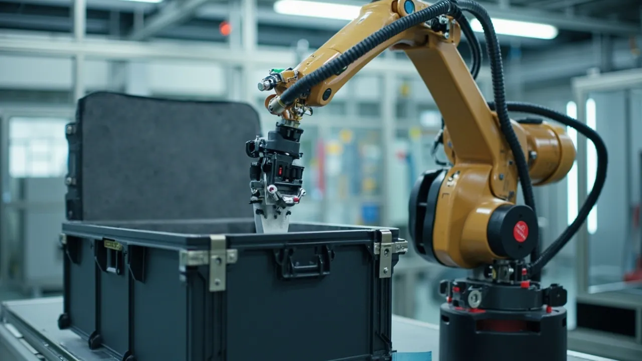
Protecting a collaborative robot (cobot) during transport is not mainly about resisting impact. It is about holding joint posture unchanged for the entire journey, isolating vibration energy from the harmonic gearboxes, and keeping the teaching pendant and cable assemblies out of the load path. A typical 6-axis cobot weighs 10 to 45 kg, and each joint contains a harmonic reducer, a frameless torque motor and an absolute encoder. A single peak acceleration above roughly 30 g can shift the encoder zero reference or initiate micropitting on the gear flanks. Once that reference drifts, the customer must re-zero every axis on site, and the resulting downtime costs far more than the case itself. The correct approach is therefore: use a custom EVA/EPE composite liner for three-dimensional restraint, use posture locks and support blocks so gravity and inertia loads bypass the joints and pass into the case structure, and use an IP65/IP67 seal plus a pressure-equalization valve to keep moisture, dust and differential pressure away from the robot. This article is written for robot integrators, OEMs and overseas channel buyers, and provides structural parameters, test references and acceptance methods that can be applied directly.
What actually frustrates procurement teams is not the unit price of the case. It is the hidden cost of "dead on arrival". A single ocean leg plus final-mile truck delivery exposes a cobot to at least three transshipment points, two lift-and-drop risks, and 30 to 60 days of temperature and humidity cycling. If the liner is nothing more than generic sponge inside a carton, the arm can micro-move 2 to 5 mm inside the case, and a few hundred kilometers of road vibration is enough to fatigue the flexspline of a harmonic reducer. This article breaks the cobot system into four protection objects, the joint arm, the teaching pendant, the controller and the cable set, and gives the liner construction, posture-locking method, sealing class and test criteria for each. It also explains what JUNZHJIA can deliver in custom liners and OEM/ODM case development.
Table of Contents
- 1. Why collaborative robots are harder to ship than traditional industrial robots
- 2. Four typical transport damage modes and their failure mechanisms
- 3. Arm posture locking: which pose should the robot be fixed in
- 4. Case structure: shell, ribs and stacking load capacity
- 5. Liner system: EVA, EPE and composite layer construction
- 6. Independent protection for teaching pendants, cables and handheld units
- 7. Zoned packing for controllers and I/O modules
- 8. Sealing class and pressure equalization: IEC 60529, GB/T 4208, IP65 and IP67
- 9. Transport test references: ISTA, GB/T 4857, ASTM D4169 and MIL-STD-810H
- 10. Material selection and flammability requirements (UL94)
- 11. Temperature, humidity, condensation and long-term storage
- 12. Customization workflow: from selection to drawings to samples
- 13. Factory inspection and incoming acceptance (AQL)
- 14. Frequently Asked Questions
- 15. Conclusion and Related Reading
1. Why collaborative robots are harder to ship than traditional industrial robots
Traditional industrial robots are usually shipped as complete machines on dedicated timber crates. The case is large, the liner is crude, but the center of gravity sits low. Collaborative robots are the opposite: light self-weight, long reach, large joint overhang and a high center of gravity. A typical 6-axis cobot has a body weight of 12 to 25 kg and a reach of 600 to 1300 mm, and the maximum overhang from the base joint can exceed 800 mm. When the truck brakes at 0.5 g longitudinal acceleration, the bending moment generated at the end of that overhang is amplified stage by stage along the arm links and is finally absorbed entirely by the base joints (J1 and J2). This is the fundamental divergence between cobot transport protection and ordinary equipment cases: you cannot size the liner by weight alone, you must design by moment arm and by posture.
The second difference is that joint zero references have already been calibrated. Before shipment, a cobot goes through assembly zeroing and multi-turn encoder counting, and some models also have their joint torque sensors calibrated. Continuous micro-vibration during transport, impacts above the rated limit, or encoder reading drift caused by humidity and temperature cycling inside the case can all invalidate that calibration. The customer then sees alarm messages about a lost zero reference or a joint position deviation beyond limits, requiring re-zeroing or even a factory return. The after-sales cost of such an incident is frequently more than ten times the cost of the case.
The third difference is that the teaching pendant and cables are high-value, fragile items. The pendant face carries a capacitive touchscreen, a joystick, an emergency stop button and a key switch, making it a precision human-machine interface. Its own ingress protection is typically only IP54, and in a few models IP65. It is not suitable for long-distance shipment without an outer case. The joint power and encoder cables usually terminate in custom circular connectors with fine pins and delicate shielding. If a heavy object presses or kinks the cable, the shield can break and produce intermittent communication faults that are extremely hard to localize in the field.
Conclusion: a collaborative robot transport case must satisfy three conditions at the same time: the arm posture can be locked, the overhang bending moment has support, and accessories do not interfere with the robot body. If any one of these is missing, the transport risk is simply transferred to the customer's commissioning labor.
2. Four typical transport damage modes and their failure mechanisms
To design the case properly, you first have to understand how damage happens. Based on robot service statistics, transport-related cobot failures fall into four categories.
Category one: encoder zero drift. Absolute encoders, mostly multi-turn magnetic or optical types, can suffer multi-turn counting jumps above roughly 25 to 50 g peak acceleration, or accumulate error under prolonged resonance between 5 and 15 Hz. The symptom is a position deviation of 0.1 to 2 degrees after power-up, or an outright zero-reference loss alarm. This damage leaves no external trace, which makes it the most invisible and the most expensive category.
Category two: harmonic reducer flexspline fatigue and gear flank micropitting. The flexspline wall thickness is only 0.3 to 0.8 mm, and it fatigues under alternating load. If the arm is not locked during transport and the joints are free to swing, road vibration repeatedly micro-deforms the flexspline and initiates early pitting. The symptom is rising running noise and repeatability degrading from plus or minus 0.02 mm to plus or minus 0.1 mm.
Category three: surface and cosmetic damage. Joint housings are typically die-cast aluminum with anodizing, or engineering plastic shells. Without a liner, or with insufficient foam thickness, case displacement causes paint chipping, scratches and seal ring compression marks, which then affect cosmetic acceptance and the customer's first impression.
Category four: accessory failure. Cracked pendant screens, jammed emergency stop buttons, bent connector pins, cables crushed into hard kinks by the robot body, damaged end-flange threads. These occur at high frequency, cost relatively less per event, but they directly delay the customer's time-to-first-run.
| Damage mode | Main cause | Typical symptom | Protection measure |
|---|---|---|---|
| --- | --- | --- | --- |
| Encoder zero drift | Peak shock above 25 to 50 g, 5 to 15 Hz resonance | Zero-reference loss alarm, position deviation beyond limit | Posture lock, damped liner, shock indicator label |
| Harmonic reducer fatigue | Joints swinging freely, sustained alternating load | Rising noise, degraded repeatability | Joint support blocks, three-point restraint |
| Cosmetic and seal-face damage | 2 to 5 mm micro-movement inside the case | Paint chipping, seal ring compression marks | Contour-molded liner, zero-clearance design |
| Accessory and cable failure | Compression by heavy parts, pin loading | Cracked screen, bent pins, intermittent communication faults | Separate cavities, controlled cable bend radius |
This table also explains why generic sponge liners are unsuitable for cobots. Sponge has high compression set and slow recovery. After 30 days in the case it sags, and internal clearance grows from zero to more than 3 mm, which directly raises the probability of categories one and two.
3. Arm posture locking: which pose should the robot be fixed in
This is the most commonly overlooked step in cobot case design, yet it decides the outcome. The core question is simple: what posture should the robot keep during transport?
There are three engineering options, each with trade-offs.
Option A: zero posture (all axes at 0 degrees). The advantage is a standard configuration and no re-homing needed after installation. The disadvantage is that the arm links are fully extended, producing the largest overall envelope and the longest overhang moment arm, which maximizes case volume and liner cost. Suitable for small 4-axis models or cobots with a reach under 600 mm.
Option B: folded storage posture. Fold J2 and J3 inward and bend J5 so the end effector approaches the base, producing a roughly cubic, compact envelope. The advantage is that case volume can shrink by 30 to 45 percent, with the shortest moment arm and the smallest bending moment. The disadvantage is that joint support blocks are required inside the case to carry the arm links, and the customer must unfold the robot before first power-up. This is currently the most widely used approach for medium and large cobots.
Option C: partial disassembly. Remove the end flange, tooling and some accessories and pack them separately. Suitable when the payload is heavy or the tool is long, for example a welding torch or a fixture.
Whichever option is chosen, three actions must be completed.
- Confirm brake state and whether a transport mode exists. Most cobots lose joint holding force when power is removed, meaning the joints become free, or can be pushed by hand. Before packing, confirm whether a mechanical locking pin is used, whether a shipping fixture is supplied with the case, and, if the model supports a transport mode, enable it to freeze the brake state.
- Support block placement. Support blocks must sit on the rigid section of the arm link, close to the joint housing. They must never press on the harmonic reducer output end, the torque sensor mounting face or the cable exit. As a rule, use at least two support points per arm link.
- End flange protection. The flange is a precision datum. Flatness and runout requirements are typically in the 0.02 to 0.05 mm range. Use a dedicated flange cover with a soft gasket, and never allow the flange to contact the case wall or a hard liner edge.
Rule of thumb: for a 6-axis cobot with a reach of 900 mm or more, a folded posture with three support blocks and two restraint blocks can bring peak joint acceleration during transport from 40 to 60 g in the free state down to below 15 g, depending on road conditions and the number of packaging layers.
4. Case structure: shell, ribs and stacking load capacity
Cobot cases are usually produced by rotational molding or injection molding. The choice depends on volume and size. Below 500 units per year with a single-piece dimension above 900 mm, rotational molding is more economical. At high volume and standardized dimensions, injection molding gives better wall-thickness consistency and appearance. To evaluate the balance between tooling investment and unit price, see custom protective case mold cost analysis.
Four design points matter structurally.
Wall thickness and ribs. The main wall is typically 3 to 5 mm, and rotomolded parts can locally reach 6 to 8 mm. Load-bearing case bottoms need a grid of reinforcing ribs, with rib height of 8 to 15 mm and rib spacing of 80 to 120 mm. If stacking of three layers or more is required, add a load-bearing base plate, which may be wood, aluminum or a PP honeycomb panel, to transfer the upper load directly into the vertical case walls instead of into the liner and the robot.
Lid deflection control. A large lid will bow inward under stacking load. If the liner does not match the contour, that bow presses directly on the top joint of the robot. The solution is a locating lip on the inside of the lid plus 3 to 5 mm of pre-compression allowance in the top liner layer.
Handles and wheels. With the robot installed, total case weight is often 30 to 80 kg, so ergonomic side handles are mandatory, or a wheel and telescoping-handle configuration should be added. Wheel placement must avoid the area outside the center-of-gravity projection to prevent tipping during handling. Related design considerations are covered in case wheels and trolley handle design.
Stacking and tipping. Print or mold an "this side up" arrow, the maximum stacking layers and a "do not step" marking on the case side. If the customer requires palletized shipment, work backward from the pallet footprint, commonly 1200 by 1000 mm or 1200 by 800 mm, so the case does not overhang the pallet and leave an unsupported span.
5. Liner system: EVA, EPE and composite layer construction
The liner determines vibration transmissibility and is the technical core of a cobot case. Common material combinations and their applications are shown below.
| Material | Density (kg/m3) | Compression set | Resilience behavior | Recommended use |
|---|---|---|---|---|
| --- | --- | --- | --- | --- |
| EVA (ethylene vinyl acetate) | 60 to 120 | Low | Fast, stable across repeated compression | Main molded liner, support blocks, restraint blocks |
| EPE (expanded polyethylene) | 20 to 40 | Very low | Slow but complete recovery | Cushioning layer, outer energy absorption |
| PE foam (XPE/IXPE) | 30 to 70 | Low | Moderate | Thin facing, anti-scratch layer |
| PU sponge | 20 to 35 | High | Good initially, sags over time | Not recommended for long-cycle shipment |
| ESD PE or EVA (surface resistance 10^6 to 10^9 ohm) | 60 to 110 | Low | Fast | Electronic control parts, sensor-bearing components |
The recommended construction is a three-layer composite. The outer layer is EPE at 20 to 40 kg/m3 and 20 to 40 mm thick, absorbing drop energy. The middle layer is EVA at 60 to 90 kg/m3 and 30 to 60 mm thick, providing molded restraint and structural support. The inner layer is thin PE foam or a flocked fabric facing, 2 to 5 mm thick, providing anti-scratch protection and consistent friction. If the robot body exposes circuit boards or communication modules, replace the inner layer with an ESD-safe material. For a detailed comparison of material options, see case foam material comparison and the custom foam inserts guide.
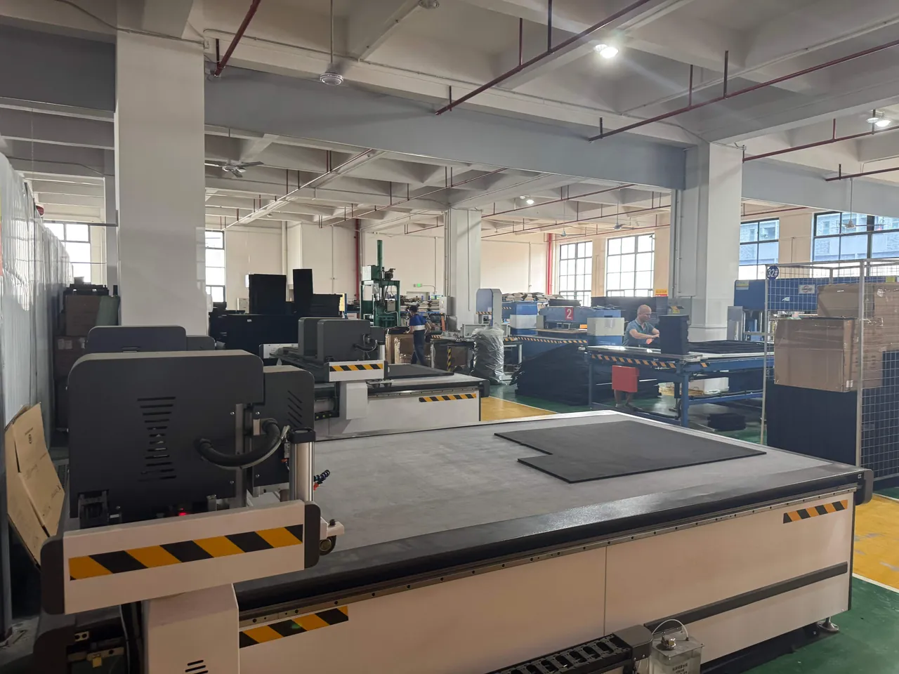
There are two molding routes. The first is CNC carving, suitable for single units or small batches with complex geometry and fast delivery requirements. Accuracy reaches plus or minus 0.5 mm and no tooling is needed. The second is compression molding or thermoforming, suitable for annual volumes above 500 units with a fixed shape. Unit cost is lower and consistency is better, but tooling cost applies. For cobot liners, JUNZHJIA typically uses a combined route: CNC prototype validation followed by molded production. The CNC insert validates fit and extraction force first, then the verified 3D data goes to tooling, which significantly reduces the risk of mold rework.
Extraction force and ergonomics matter equally. Leave 0.5 to 1.5 mm of assembly clearance between the liner cavity and the robot body, depending on case tolerances, and keep extraction force between 30 and 80 N. Too tight and a field engineer cannot remove the robot alone. Too loose and the restraint loses meaning. For models above 25 kg, design a lift-out recess or webbing handle into the liner, and pair it with a pressure-equalization valve to avoid a suction effect when opening.
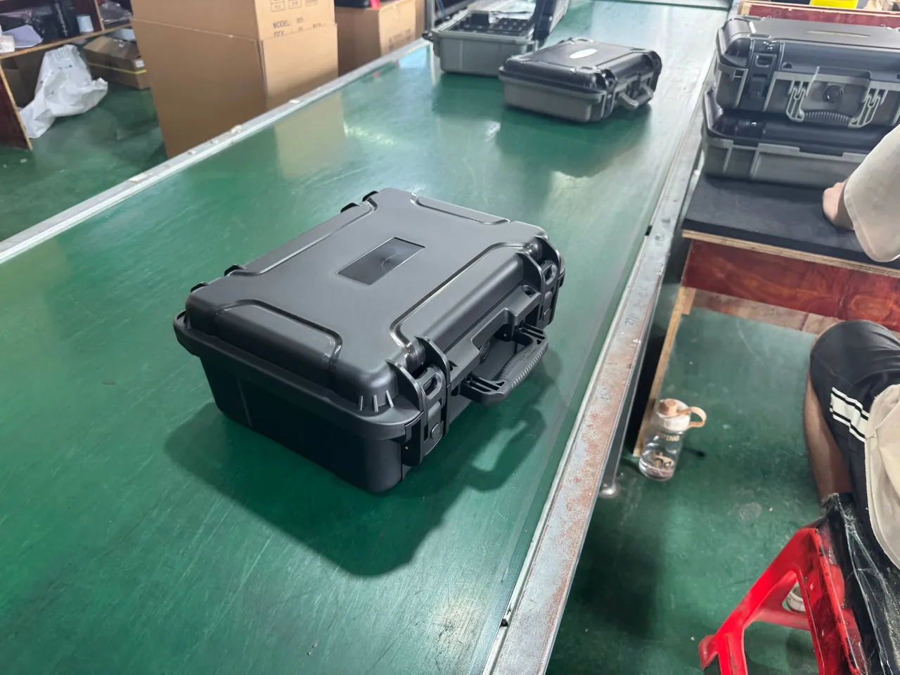
6. Independent protection for teaching pendants, cables and handheld units
The teaching pendant is one of the most contradictory items in a cobot system: high unit price, fragile structure, and nearly every project keeps one spare. Its transport protection points are as follows.
Screen protection. Pendant screens are mostly 8 to 12 inch capacitive touch panels with a glass cover. During transport the screen must face away from any hard contact. Leave an 8 to 15 mm EPE cushioning cavity above the screen and design a support frame around the perimeter so that pressure lands on the pendant housing bezel rather than the center of the glass. If the pendant ships with a protective film, leave it in place.
Joystick and button protection. A three-axis joystick is a mechanical assembly, and lateral pressure shifts its zero point. Design a relief cavity at least 40 mm in diameter and 10 mm deep around the joystick so the lid cannot press on it. Emergency stop buttons, usually mushroom-head types, must not take axial load, so provide a relief cavity or a removable protective cap.
Cable coiling. Pendant cables are commonly 3 m, 5 m or 10 m, with shielding and multiple signal conductors. Never allow a hard kink. The minimum coil diameter should be at least ten times the cable outer diameter, typically 150 mm or more. Use a dedicated cable channel, optionally with an EPE base, protect both connector ends with dust caps, and do not bend the cable within 50 mm of the connector-to-cable transition.
Separate zoning. A pendant must never share a cavity with the robot body. There are two reasons: the body weight is transmitted through the liner into the accessory cavity, and once the body micro-moves inside the case, the accessories take secondary impacts. The recommended approach is to divide an accessory zone inside the main case with a partition, or to use a two-case solution with a main case and an accessory case, where the accessory case can be reused as a field toolbox.
7. Zoned packing for controllers and I/O modules
A cobot controller is usually a 19-inch rack-level or wall-mount enclosure containing power supplies, drive boards, a safety controller implementing safety functions at ISO 13849-1 PLd level, and I/O expansion modules. Its transport protection priorities are completely different from the robot body.
Four critical points for the controller:
- Secure plug-in modules. I/O cards, communication cards, SD cards and CF cards should all be removed and packed separately, or retained with anti-loosening clips. Many field failures trace back to a half-seated card after transport.
- Internal harnesses and connectors. Wire harnesses inside a controller can be pulled loose by inertia during a drop. Secure them with additional cable ties before shipment, or use low-resilience EPE blocks under the four bottom corners so the enclosure does not take the bottom impact directly.
- ESD control. Mainboards and drive boards are ESD sensitive. Use antistatic shielding bags, metallized or carbon-loaded, and ESD foam with surface resistance between 10^6 and 10^9 ohm. For related solutions see ESD shielding case options.
- Vents and air intakes. Controllers have ventilation grilles. Seal them with dust tape for transport and have the site remove the tape on arrival.
Zoning recommendation: the main case carries the robot body plus flange cover; accessory case A carries the controller and I/O modules; accessory case B carries the pendant, cables, tools and calibration fixtures. When three cases ship on one pallet, the heaviest controller case goes at the bottom.
8. Sealing class and pressure equalization: IEC 60529, GB/T 4208, IP65 and IP67
The robot body itself usually has some ingress protection, with IP54 common for cobots and IP66 for some models, while controllers range from IP20 to IP54. But the ingress protection of the transport case is independent and must be specified separately.
Sealing classes are defined by IEC 60529 and GB/T 4208. Common classes and their applicability are shown below.
| Class | Dust | Water | Applicable scenario for cobot transport |
|---|---|---|---|
| --- | --- | --- | --- |
| IP54 | Dust protected, limited ingress | Splash resistant | Domestic road transport, short-term transfer |
| IP65 | Dust tight | Water jet resistant | Ocean freight plus inland delivery, open-air handling |
| IP67 | Dust tight | Temporary immersion, 1 m for 30 min | Multimodal transport, rainy season, quay storage |
| IP68 | Dust tight | Continuous immersion, by agreement | Special immersion scenarios, higher cost |
Seal material selection. Case gaskets are commonly EPDM or silicone sponge, used with a labyrinth or double-lip profile. EPDM offers good weather resistance at low cost and works from minus 40 to plus 100 degrees Celsius. Silicone covers a wider range, from minus 60 to plus 200 degrees Celsius, but costs more and tends to attract dust. Keep compression between 30 and 40 percent. Compression set is the main cause of long-term seal failure.
A pressure-equalization valve is mandatory, not optional. A sealed case develops a pressure differential in several situations: packing at high temperature then cooling in an air cargo hold or winter transport; high-altitude road transport; and day-night temperature cycling in ocean freight. The differential can either lock the lid so it cannot be opened, or draw moisture and dust inward at the moment the pressure releases, destroying the seal. Fitting a pressure-equalization valve, which breathes air but not water and normally uses a PTFE membrane, lets internal pressure track ambient pressure. Selection criteria and mounting position are described in case pressure equalization valve. JUNZHJIA can configure custom cases to a specified IP class and valve brand, and can supply the corresponding seal inspection records.
One detail before closing the lid: the gasket must stay clean. Sand grains, metal chips and cable jacket debris stuck to the gasket form leak paths and can turn an IP67 case into something closer to IP30. Keep the packing area clean and wipe the seal channel with a clean cloth.
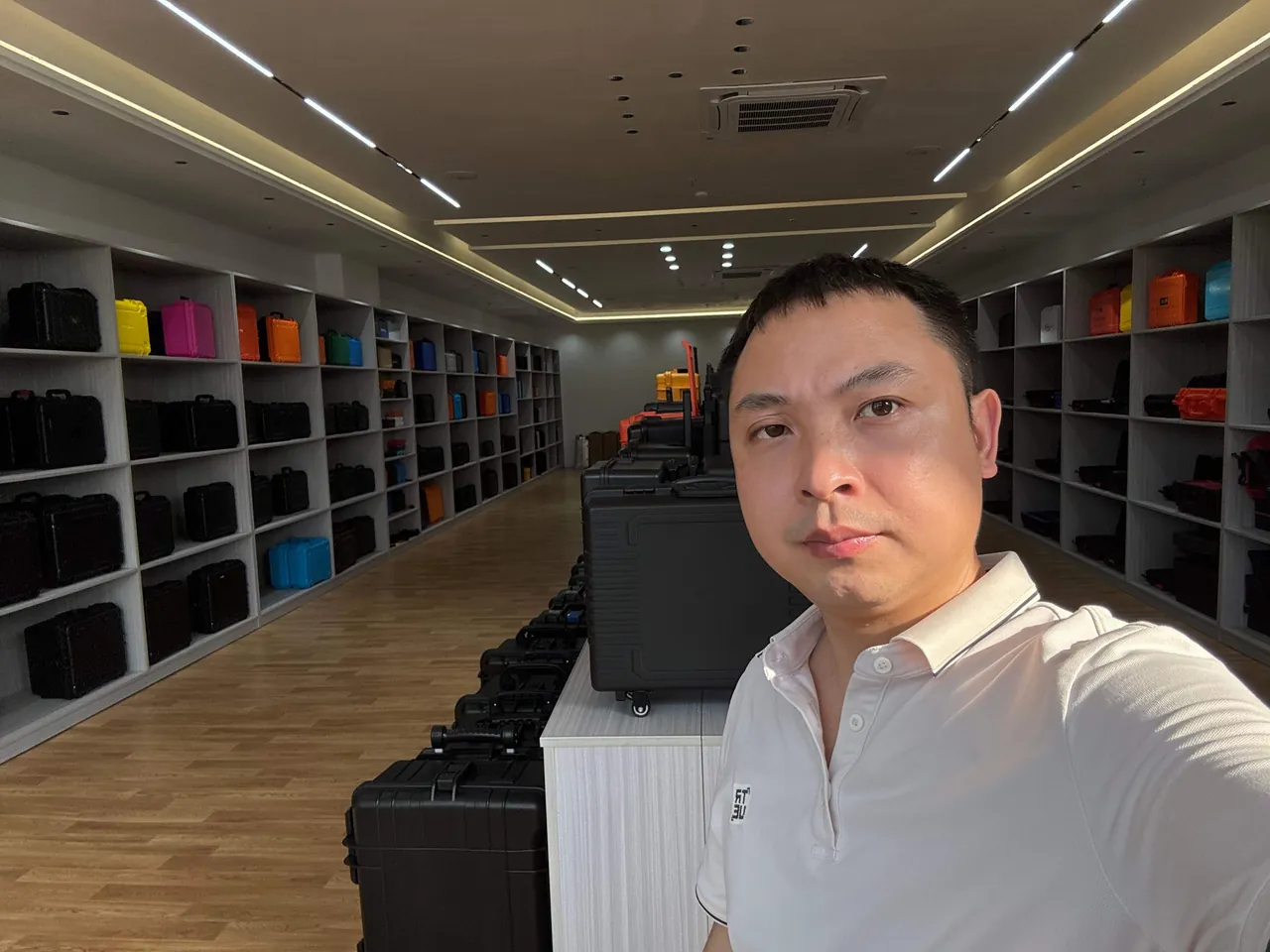
9. Transport test references: ISTA, GB/T 4857, ASTM D4169 and MIL-STD-810H
Whether a cobot case is acceptable is not decided by how sturdy it looks, but by reproducible testing. The commonly used standards are as follows.
ISTA (International Safe Transit Association) covers different logistics modes. ISTA 2A is a simulated performance test for individual packaged products up to 68 kg, covering conditioning, drop, vibration and compression. ISTA 3A is for parcel delivery systems and suits smaller accessory cases shipped by courier. ISTA 3E covers unitized load compression and vibration. Cobot body cases are normally designed against ISTA 2A or ISTA 3E. For a detailed walkthrough, see ISTA transport testing procedure.
The GB/T 4857 series is the Chinese basic test standard for transport packages, aligned with the ISO 4180 framework and covering drop, stacking, vibration and impact parts. When the customer is a domestic robot manufacturer or its supplier, a GB/T 4857 report is usually required. See GB/T 4857 transport packaging testing.
ASTM D4169 is a performance test standard for distribution cycles. It combines test sequences by defining a distribution cycle and an assurance level, which suits a full multimodal evaluation. See ASTM D4169 distribution cycle testing.
MIL-STD-810H is frequently cited for its method-level environmental testing, including Method 501 high temperature, 502 low temperature, 507 humidity, 514 vibration and 516 shock. It must be stated clearly that citing MIL-STD-810H means only that the environmental test methodology is referenced. It does not mean the product holds any military certification, and it does not mean the product is a military product. Civilian industrial equipment cases cite this standard in order to use its mature test conditions and methodology.
Recommended test conditions, as engineering values that must be confirmed against the actual logistics route:
- Drop: one corner, three edges, six faces, with drop height graded by weight; 400 to 600 mm is common for the 30 to 80 kg class.
- Random vibration: 5 to 200 Hz, PSD per the ISTA 2A spectrum, 30 to 60 minutes per axis.
- Compression: actual stacking layers multiplied by a safety factor, commonly 1.5 to 2.0.
- Temperature and humidity: minus 20 to plus 60 degrees Celsius at 85 percent relative humidity, cycling to simulate conditions inside an ocean container.
The decisive evidence is inside the case, not outside it. Fit one shock indicator label on the robot base and one on the end flange, with thresholds commonly selectable at 25 g, 50 g and 100 g, and place a temperature and humidity data logger inside the case. On arrival you can immediately judge whether transport exceeded limits, and liability can be assigned with evidence. Such data is far more reliable than a visual inspection.
10. Material selection and flammability requirements (UL94)
Case and liner materials must satisfy mechanical performance, weathering resistance and flammability requirements at the same time.
Case material comparison:
| Material | Impact resistance | Weathering and UV | Chemical resistance | Typical flammability rating | Applicable scenario |
|---|---|---|---|---|---|
| --- | --- | --- | --- | --- | --- |
| PP (polypropylene) | Good, weaker at low temperature | Requires UV stabilizers | Excellent | UL94 HB, can be modified to V-0 | General rotomolded cases, cost-effective option |
| Copolymer PP (PPC) | Excellent, good low-temperature toughness | Good | Excellent | UL94 HB | First choice for ocean freight and cold climates |
| ABS | Excellent | Moderate, yellows over time | Moderate | UL94 HB to V-0 | Injection-molded cases, high appearance requirements |
| PC (polycarbonate) | Excellent | Good, may need UV coating | Fair, sensitive to alkalis and some solvents | UL94 V-0, V-2 possible in thin walls | High strength, transparent window needs |
| PA with glass fiber | Excellent | Good | Good | UL94 V-0 when modified | Latches, hinges, load-bearing parts |
UL94 flammability ratings are the general criterion for plastic combustibility. HB is the lowest horizontal-burning rating. V-2, V-1 and V-0 are vertical-burning ratings in increasing severity, and 5VB and 5VA are stricter still. For robot transport cases, most customer specifications require case material at UL94 HB or better, and liner material inside electronic accessory cases at UL94 V-0. If the case is used in air transport or the customer has strict internal rules, the whole case may be required at V-0.
Hinges, latches and gaskets form the critical trio and are also the life-limiting parts. Evaluate hinges by open-close cycle life, commonly specified between 5000 and 20000 cycles, and by torque decay. Evaluate latches for self-locking reliability under vibration. Selection guidance and failure modes are covered in toolbox hinge, latch and seal construction.
Environmental compliance. Cases exported to the European Union must satisfy RoHS and REACH requirements. Some blowing agents used in foam liners are restricted, so request material MSDS and RoHS reports during procurement. JUNZHJIA can provide property tables for common case and liner materials, RoHS and REACH declarations, and UL94 test reports subject to material batch availability.
11. Temperature, humidity, condensation and long-term storage
Cobots are not extremely sensitive to humidity itself, since the body is mostly metal and sealed structures. The real threat is condensation. When a case moves from a cold environment into a warm, humid one, the equipment surface temperature drops below the dew point and moisture condenses on joint housings, flange faces and connector pins. Steel parts corrode, and electrical connectors lose insulation resistance or develop micro-shorts.
Three control measures:
- Active desiccation. Place desiccant inside the case, montmorillonite or silica gel, commonly 30 to 100 g per case depending on internal volume and shipment duration, and pair it with a pressure-equalization valve to form a passive breathing but moisture-retarding system. If the shipment exceeds 60 days or the destination is a high-humidity region, use reusable silica gel packs and label the replacement interval.
- Temperature soak before opening. State in the work instruction that the equipment must not be unpacked immediately on arrival. Let it stand in the site environment for 4 to 12 hours depending on season and temperature difference, then open. This markedly reduces condensation.
- Corrosion prevention. Apply rust-preventive oil or film to flange faces, threaded holes, exposed rails and bearing surfaces. Note that the oil must not contaminate encoder gaps or optical components.
Long-term storage beyond six months needs three extra precautions. First, keep the joints in the braked or transport-locked state so that self-weight does not press on a single tooth contact pattern over months. Second, inspect desiccant condition every three months. Third, never store the case directly on the floor. Use a pallet to avoid ground moisture and standing water.
12. Customization workflow: from selection to drawings to samples
A cobot transport case is a project-based custom product. The standard process, following JUNZHJIA practice with milestones adjusted per project, is as follows.
- Requirements gathering, 1 to 3 working days: robot model, envelope dimensions, weight, reach, folded posture drawing, accessory list, logistics route, target IP class and test requirements, annual volume.
- Concept and structural design, 3 to 7 working days: case dimensions, material, wall thickness, stacking layers, liner layering and support-block positions, with 2D drawings and a 3D model for confirmation.
- First article, 7 to 15 working days: CNC-carved liner plus a first-article case shell, with physical packing validation covering posture locking, extraction force and handling ergonomics.
- Test validation, 5 to 10 working days: drop, vibration and compression testing to the customer-specified standard, which may be delegated to a third-party laboratory, with shock and climate loggers placed inside the case.
- Tooling and mass production, lead time depends on the tool: compression-molded liner or molded case shell, full inspection of the first article, then AQL sampling in production.
- Delivery and documentation: a packing work instruction covering posture locking steps and unpacking sequence, material declarations, and test reports where testing is delegated.
Three delivery documents that are easily overlooked:
- Packing and unpacking SOP: specifies robot posture, locking pin positions, lifting points and the unpacking sequence. Without this document the customer re-invents the process on site and may cause secondary damage.
- Accessory list and location map: a photo or diagram showing where each accessory sits inside the case, preventing items from being left behind.
- Maintenance and repacking notes: gasket cleaning method, desiccant replacement interval, pressure valve inspection. Related maintenance methods are covered in how to clean a protective case.
13. Factory inspection and incoming acceptance (AQL)
Factory inspection of cases and liners should follow the counting sampling plans of GB/T 2828.1, equivalent to ISO 2859-1. Commonly used AQL levels as recommended engineering values are shown below.
| Inspection item | Defect class | Recommended AQL | Method |
|---|---|---|---|
| --- | --- | --- | --- |
| Appearance, color, scratches, burrs | Minor | 2.5 | Visual, color card comparison |
| Dimensions and fit | Major | 1.0 | Calipers, tape, gauges |
| Seal performance | Major to critical | 0.65, or 100 percent | Pressure decay or water immersion test |
| Hinge and latch function | Major | 1.0 | Cycle test, pull force test |
| Liner fit and extraction force | Major | 1.0 | Physical assembly, force gauge |
| Marking and documents | Minor | 4.0 | Visual, document verification |
Seal performance should be inspected 100 percent rather than sampled. Seal failure is a critical defect and is hard to trace after shipment. Two methods are common. The first is pressure decay, where the sealed case is charged to a specified pressure and held for 30 to 60 seconds while decay is monitored. The second is water immersion or spray, performed under the IPX5 and IPX7 conditions of IEC 60529. Related acceptance methods are described in custom case acceptance and AQL sampling.
Incoming acceptance checklist, recommended to ship with the case and be filed:
- Outer packaging and pallet condition, and whether stacking or tilt indicator labels have changed color.
- Whether shock indicator labels have triggered, with the trigger direction recorded.
- Export and interpretation of internal temperature and humidity logger data.
- After opening, verify the robot posture matches the packing record and the locking pins are in place.
- Visual inspection of the flange face, housing and pendant screen.
- Complete the temperature soak before power-up, then run an all-axis zero check and sample the repeatability.
Any dispute over "accuracy abnormality after transport" is ultimately resolved by three evidence sets: shock labels, climate logger data and packing photographs. It is advisable to write these three items into the technical annex of the purchase contract.
14. Frequently Asked Questions
Q: Does a collaborative robot transport case really need a custom liner, or can generic sponge work? A: For a cobot, a custom liner is strongly recommended. Generic sponge has three problems. It has high compression set, so it starts to sag 20 to 30 days after packing and internal clearance grows from near zero to more than 3 mm, letting the robot body micro-move in transit. It cannot provide posture locking or support blocks, so the bending moment of an extended arm has to be absorbed by the joints. And it cannot zone the interior, so the pendant and cables get pressed by the robot body. A custom liner can reduce peak joint acceleration by roughly 50 to 60 percent as an engineering estimate, and it transfers load from the joints into the case structure through contour restraint. If the application is a local same-day transfer under 50 km, generic sponge inside a timber crate can serve as a temporary solution, but it is not advisable for inter-provincial or cross-border shipment. JUNZHJIA offers a full custom liner workflow from 3D scanning to CNC first article, so a single validation unit can be produced before committing to tooling.
Q: Should the arm be shipped in the zero posture or a folded posture? A: It depends on model size and logistics. Small cobots with a reach under 600 mm can stay in the zero posture, which has the advantage of being ready to use with no re-homing, but the largest overall envelope. Models with a reach of 600 mm or more should use a folded storage posture, folding J2 and J3 inward and bending J5 so the end effector approaches the base. This can reduce the overall envelope by 30 to 45 percent with the shortest moment arm and the smallest joint bending moment. A folded posture requires two supporting measures: support blocks placed on the rigid section of each arm link close to the joint housing, with at least two support points per link, and an unpacking and re-homing SOP that specifies the axis recovery sequence. If a long tool such as a welding torch or fixture is mounted, remove it and pack it separately so the tool does not amplify the moment arm. In every posture, confirm whether the model supports a transport mode and enable it so the joint brakes are frozen.
Q: The robot body is rated IP54. Does the transport case still need IP67? A: Two distinct concepts are involved. Body IP54 is the equipment's own protection in operation. Case IP67 is the protection of the packaging system within the logistics chain. They are evaluated independently and cannot substitute for each other. Harmonic reducers, encoders and connectors are sensitive to dust and moisture, and the interior of an ocean container stays at 70 to 90 percent relative humidity for extended periods, while open quays add rain exposure and short-term standing water. If the whole route is domestic road transport in a covered truck, an IP54 case is basically sufficient. If ocean freight, multimodal transport, rainy-season handling or quay storage is involved, specify at least IP65 and IP67 where conditions allow. Note that an IP67 case must have a pressure-equalization valve, otherwise day-night temperature differences or high-altitude transport will lock the lid shut or cause an instantaneous seal rebound. IP67 is also not free, since the seal construction, latch pressure and inspection operations all add cost, so choose against the actual logistics route rather than maximizing the rating by default.
Q: If the robot reports a lost zero reference or an out-of-limit position deviation after transport, how is liability determined? A: Build the evidence chain during procurement. First, shock indicator labels, one on the base and one on the end flange, with thresholds chosen against the model's tolerance, commonly 25 g, 50 g or 100 g. Once triggered, the label cannot be reset and it records the direction. Second, a temperature and humidity logger inside the case with a sampling interval of 10 minutes or less, which can reconstruct the climate cycle and show whether extreme humidity occurred. Third, packing photographs and video recording the robot posture, locking pin positions and accessory placement for comparison with the unpacking condition. With all three evidence sets, it becomes possible to distinguish transport over-limit from inadequate packaging design or a packing operation error. It is also advisable to state in the contract annex that the equipment must soak for 4 to 12 hours before power-up and that the unpacking process should be recorded. If the SOP was not followed, the liability position changes.
Q: Can the teaching pendant be shipped in a small generic equipment case instead? A: Yes, and it is often more sensible than putting it in the main case. The pendant is a high-value, fragile accessory, and a separate compact case with IP65 class and a custom liner can double as a field toolbox and can be shipped directly for repair or spare-part transfer. Three design points matter. Leave an 8 to 15 mm EPE cushioning cavity above the screen so pressure lands on the bezel rather than the glass cover. Provide relief cavities around the joystick and the emergency stop button so the lid cannot press on them. Keep the cable coil diameter at least ten times the cable outer diameter, typically 150 mm or more, and avoid bending within 50 mm of either connector. If several pendants ship together as spares, use a compartmented layout with EVA dividers to prevent mutual impact. JUNZHJIA can produce CNC-molded liner solutions tailored to specific pendant models, typically with a 7 to 15 working day first-article lead time.
Q: What transport tests should a cobot case undergo, and what are the typical cost and lead time? A: A common test set includes temperature and humidity conditioning from minus 20 to plus 60 degrees Celsius at 85 percent relative humidity, drop and random vibration per ISTA 2A or GB/T 4857, compression testing at the actual stacking layers, and optionally an ASTM D4169 distribution cycle. If the customer or end user cites MIL-STD-810H, organize the corresponding items under Methods 501, 502, 507, 514 and 516, but state in the report that only the test methods are referenced and that this is not a military certification. A complete sequence usually requires 5 to 10 working days including conditioning time, longer if a third-party laboratory must be scheduled. Cost depends strongly on case size and weight, the number of test items, and whether third-party reports are required, so the test matrix should be agreed at the concept stage before quotation. A more efficient route is to validate the liner by single-component drop testing first, then run the full sequence on the complete case, which surfaces structural problems early and avoids reworking the whole design.
Q: How can a buyer tell whether a supplier's case is genuinely sealed rather than just looking sealed? A: Look at four things. First, ask whether the seal profile is single-lip or double-lip labyrinth. A double-lip design maintains contact when the lid deflects under load, whereas a single lip tends to leak. Second, ask for the design compression value of the gasket. The reasonable range is 30 to 40 percent; too low means no seal, too high accelerates compression set. Third, ask whether every unit receives an air or water seal test, by which method, whether pressure decay or immersion, and with what pass threshold. A supplier that only says testing was done without stating the method has not answered the question. Fourth, check that a pressure-equalization valve with a PTFE membrane is present. An IP67 case without a valve often fails earlier than expected in real service. Where necessary, request a live spray demonstration or a third-party test report number. Further identification methods are described in identify genuine versus fake protective cases.
Q: How many trips can a cobot case survive, and how is its service life evaluated? A: Service life depends on three parts: the shell, the latches and hinges, and the gasket. A PP or copolymer PP rotomolded shell normally lasts 5 to 10 years, but continuous open-air UV exposure or frequent drops shorten it noticeably. Latches and hinges are moving mechanical parts, with typical cycle life requirements of 5000 to 20000 open-close cycles, after which self-locking force drops or hinges loosen, so replace them by cycle count or age. The gasket is the shortest-lived element. EPDM gaskets under repeated compression plus climate cycling typically need replacement every 2 to 4 years. Replace as soon as the gasket hardens, cracks, shows permanent compression marks, or holds dust that cannot be cleaned off. For evaluation, keep a log recording shock label status and open-close counts per shipment, and perform a full inspection around the three-year point, covering gasket replacement and latch adjustment. Life estimation and replacement guidance are covered in protective case service life.
15. Conclusion and Related Reading
The value of a collaborative robot transport case is not in how thick or how hard it is. It is in getting three things right at the same time: posture locking, three-dimensional restraint, and differential pressure management. Encoder zero drift and harmonic reducer fatigue are invisible losses, and once they occur they must be paid for with re-zeroing or a factory return. Their root causes are often nothing more than a sagging generic sponge, an unlocked joint, or a missing pressure-equalization valve. Put those three items into the drawings, the liner construction, the packing SOP and the acceptance criteria, and transport risk shifts from a matter of luck to something that can be managed.
For procurement and engineering teams, a practical four-step plan is: first, set the IP class and test matrix from the logistics route; second, define the case and liner structure from the robot model and its folded posture; third, validate posture locking and extraction force with a CNC first article; and fourth, build the liability evidence chain from shock labels, climate loggers and packing photographs. JUNZHJIA, operated by Kexin New Materials (Guangdong) Co., Ltd., supports cobot manufacturers, integrators and overseas channels with custom liners, OEM/ODM case structure development, model-specific gaskets and pressure-equalization valves, plus material property tables, RoHS and REACH declarations and test coordination, covering everything from single-piece first articles to volume delivery.
Related Reading