

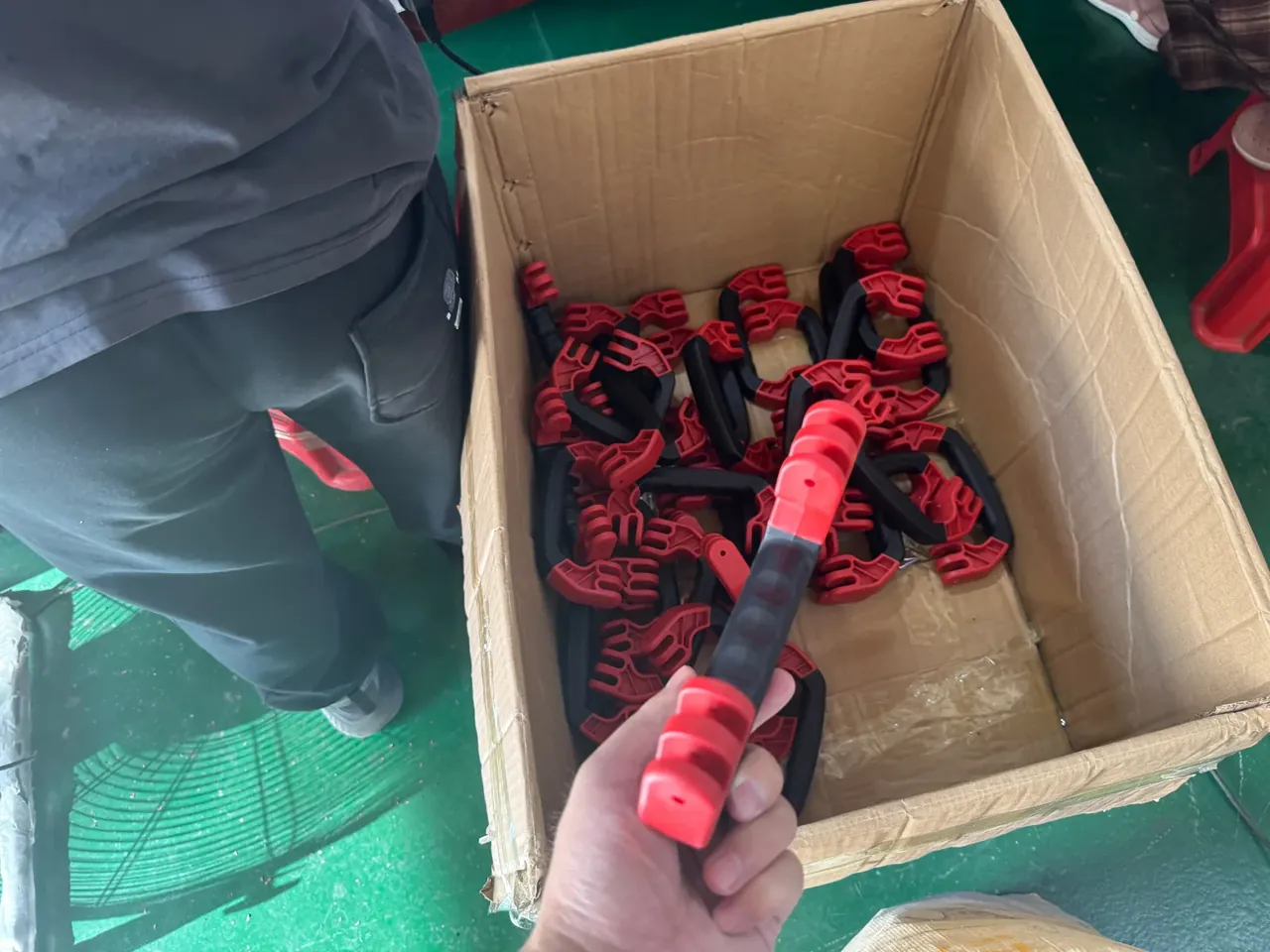
Quick answer: An M4 case threaded insert pulls out at 1200 N against 380 N for a self-tapping screw, a 3.2x gap that only holds with an 8 mm boss.
Table of contents
- Pull-out load: M4 insert at 1200 N vs 380 N
- Wall thickness and boss geometry
- Heat-set, ultrasonic and moulded-in
- Failure modes: pull-out 46%, spin-out 22%
- Cycle count and selection
- FAQ
1. Pull-out load: M4 insert at 1200 N vs 380 N
Pulled at 5 mm/min, the brass insert leaves the boss whole at 1200 N; the self-tapping screw strips at 380 N, with polymer failing before hardware in both cases.
The insert carries load on a knurled shear band. At 6.3 mm diameter and 8 mm depth it presents 158 mm², turning 1200 N into 7.6 MPa, well under the 18 MPa glass-filled PP sustains.
A screw has far less area. The ST4.2 thread is 0.6 mm high, so 8 mm of engagement leaves roughly 26 mm², and 380 N already means 15 MPa, close to the ceiling.
| Size | Brass insert, N | Self-tapping, N | Ratio |
|---|---|---|---|
| M3 | 780 | 220 | 3.5 |
| M4 | 1200 | 380 | 3.2 |
| M5 | 1750 | 520 | 3.4 |
| M6 | 2400 | 700 | 3.4 |
The ratio holds between 3.2 and 3.5 because insert shear area scales with diameter while thread height does not; at M6 the screw gains 3 mm².
Fixture stiffness skews readings more than specimens do: a flexing clamp adds 80 N to 120 N at 800 N, enough to separate two labs by 150 N.
2. Wall thickness and boss geometry
The boss runs 1.25 times insert diameter: 6.3 mm becomes 8 mm with 0.85 mm of ring wall, and 1.5 mm of polymer stays under the hole.
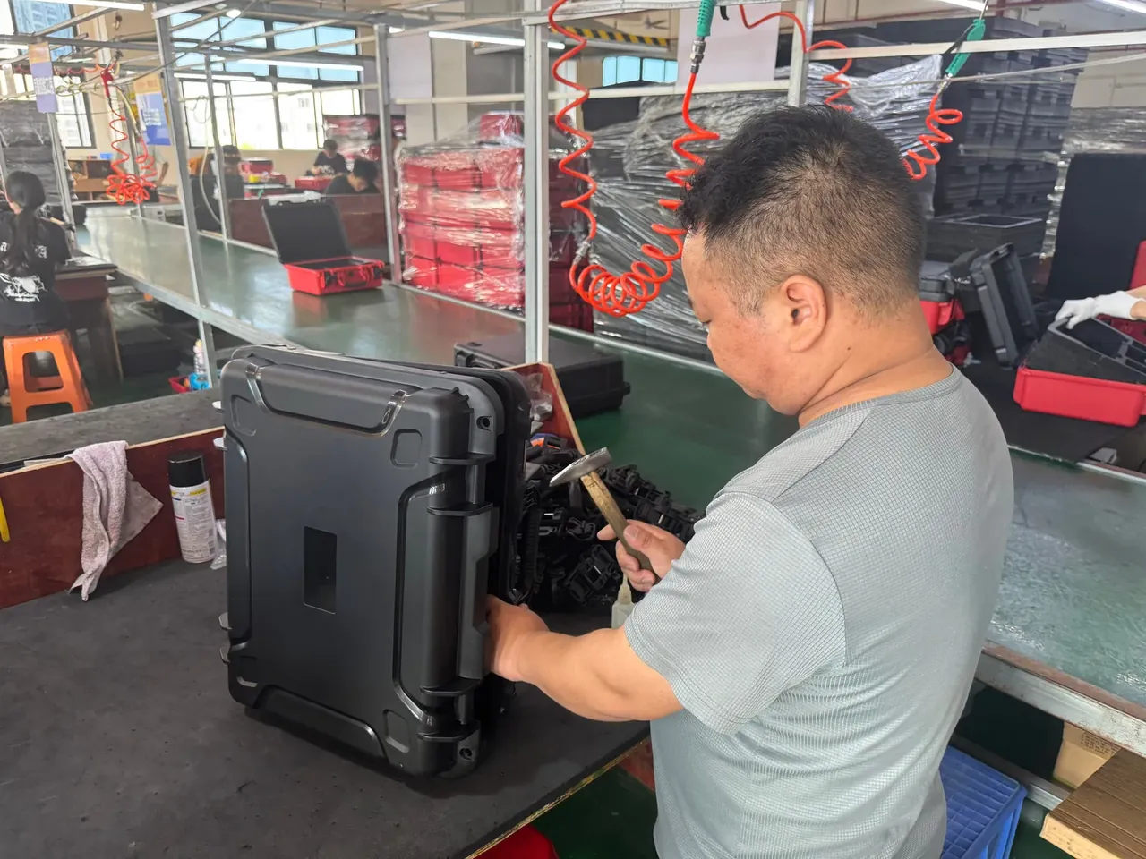
On a 2.5 mm wall the boss is where sink appears first. A 3 mm root leaves a 0.08 mm dish visible under raking light; moving the boss 6 mm inboard or coring 0.3 mm at the root drops it below 0.03 mm.
Weld lines are harder. A boss at mid-edge forces melt fronts to rejoin behind it, and that line faces the impact load, cutting drop energy 30% where it opens. Shifting the boss 15 mm, or widening it to 9 mm, moves the line into a lower-stress zone.
Holes split by process: 6.4 mm heat-set, 6.2 mm ultrasonic, 6.3 mm moulded-in. The clearance gives displaced melt room, the tight hole transmits amplitude, and the core pin is the hole.
3. Heat-set, ultrasonic and moulded-in
Heat-set is cheapest. A 270 ℃ tip presses 3 s and holds 5 s, eight seconds a joint, giving 1100 N and 4.5 N·m from a 400 USD hand tool.
Ultrasonic is fast but demanding. At 20 kHz and 28 μm the cycle takes 0.5 s and pull-out reaches 1200 N, the best of the three; the cost is a 0.3 mm flash ring needing a 0.5 mm counterbore.
Moulded-in is strongest. Pins located to 0.02 mm let melt encapsulate the knurl for 1300 N and 5.2 N·m, but tooling rises 12% and 1.2% of parts are scrapped.
| Process | Time per joint | Pull-out, N | Torque, N·m | Capital |
|---|---|---|---|---|
| Heat-set | 8 s | 1100 | 4.5 | 400 USD tool |
| Ultrasonic | 0.5 s | 1200 | 4.8 | 8,000 USD welder |
| Moulded-in | In cycle | 1300 | 5.2 | Tooling up 12% |
Volume decides, not strength. Under 1,000 units heat-set allows late changes; above 10,000 units moulded-in cuts piece cost to 0.13 USD; ultrasonic suits a frozen design.
4. Failure modes: pull-out 46%, spin-out 22%
Across 200 warranty returns: pull-out 46%, spin-out 22%, boss cracking 19%, thread stripping 13%, each tracing back to a different dimension.
If an insert has moved 0.3 mm at 800 N, engagement is under 6 mm and half the knurl sits in air; raising boss height from 8 mm to 10 mm restored 1150 N.
Spin-out appears above 3.2 N·m because straight knurling cannot grip tangentially. Three ribs 0.4 mm deep, or a diamond knurl, push spin torque to 5 N·m.
Cracking is a design fault. Below 1.0 mm of ring wall, assembly expansion splits the boss along a 45-degree path; a R0.5 fillet and 0.85 mm of wall remove about 80% of cases.
Stripping is the screw's alone, since the thread is cut not moulded. Torque is down 40% by the fifth pass and 1.1 N·m by the eighth. Field repairs go one size up, reaming 3.6 mm to 4.1 mm and thinning the wall 0.25 mm, trading spin-out risk for cracking risk.
5. Cycle count and selection
An M4 screw holds 380 N on the first pass, 228 N on the fifth and 152 N by the eighth, torque falling from 2.5 to 1.1 N·m; a brass insert still holds 1056 N at pass 25 and 840 N at pass 50.
| Planned cycles | M4 screw, N | M4 insert, N | Recommendation |
|---|---|---|---|
| 1–3 | 340 | 1180 | Screw is fine |
| 4–10 | 190 | 1120 | Insert or sleeved screw |
| 11–25 | Stripped | 1056 | Insert |
| 26–50 | Failed | 840 | Insert, diamond knurl |
Two thresholds settle the drawing: 10 or more planned cycles, or 800 N of required pull-out, mean inserts; fail both and a screw saves 0.09 USD a joint.
Cordless drivers swing torque ±20% and strip a screw by pass four, while a station limited to 4.5 N·m lets an insert reach 50.
Conclusion
Write both thresholds on the drawing and the case threaded insert choice stops being a debate: 10 or more assembly cycles, or 800 N of pull-out, means brass inserts; below both, self-tapping is cheaper. The M4 floors are an 8 mm boss, 0.85 mm of ring wall and 8 mm of depth, and losing any one costs roughly 200 N. Then pull three samples at 5 mm/min and reject any batch peaking under 900 N.
This article discusses container-side specifications and design implications only, and does not cover any handling, loading or use of the contents.
Related Reading
- How wall thickness sets boss strength
- Insert hardware and mould cost
- Injection machine specs for insert moulding
- Torque settings for case assembly stations
Related Products
- 8 Series — Gun Cases; Military Equipment Cases; Camera Equipment Cases; Drone Cases; Watch Cases; Knife Cases; First Aid Cases; Electronics Equipment Cases
- WL8-2812 PP Gun Case — model WL8-2812
- All protective cases and toolboxes: 7 series, 158 models