

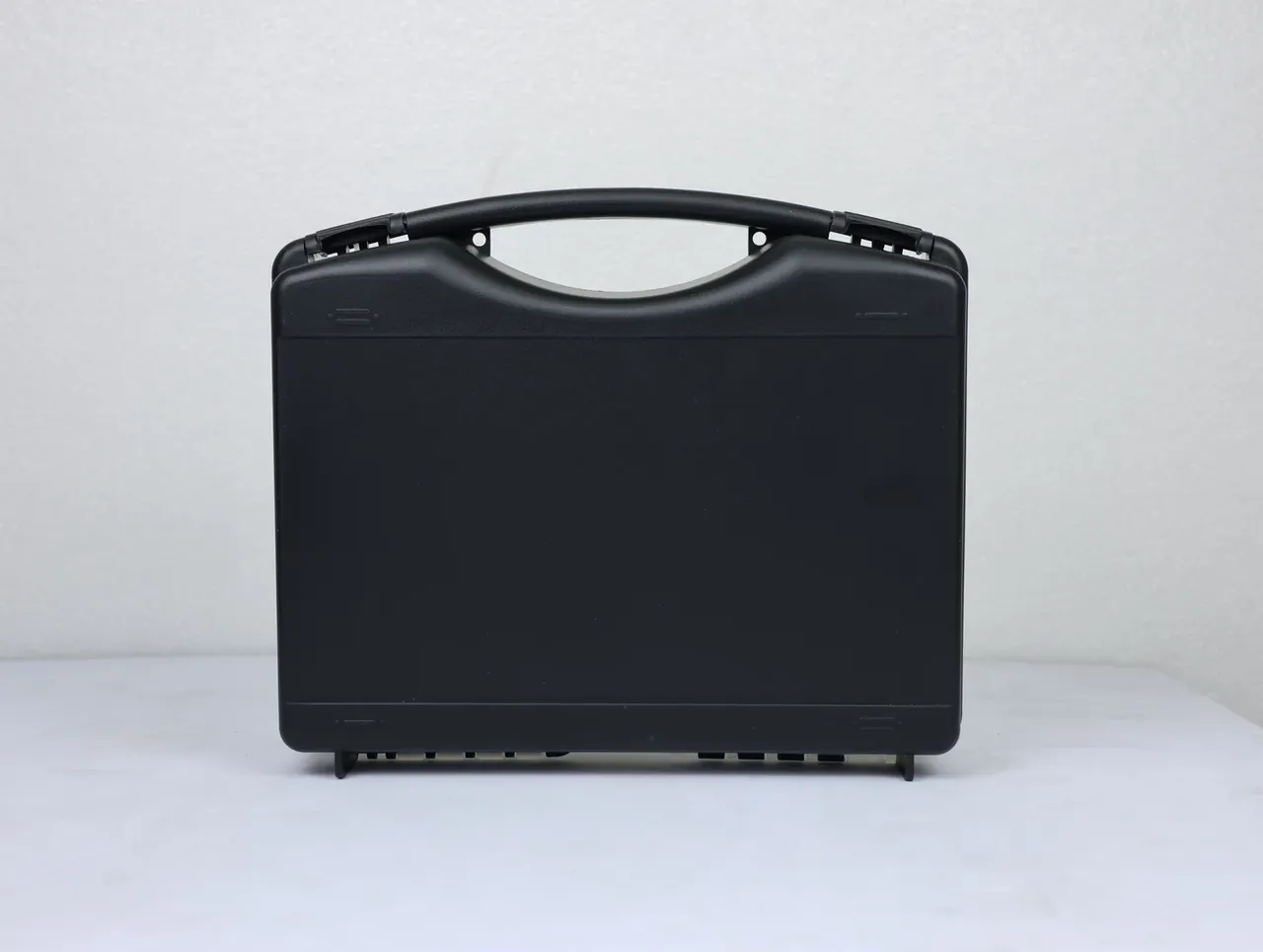
Quick answer: Fix clamp force from the pressure-bearing area, choose the screw from shot weight, then set the cycle from cooling area. Run those steps in order and a case injection molding machine lands on the right frame size.
Table of contents
- Reading the drawing for three loads
- Projected area times cavity pressure equals clamp force
- Pick the screw by shot weight
- Mould and cycle follow water lines and ejection
- Turning four numbers into a trial checklist
- FAQ
1. Reading the drawing for three loads
An instrument-case builder brought a drawing last month and asked: a 480 mm by 360 mm by 180 mm cavity, 3.0 mm walls, 2.2 kg per part, would the old 650-tonne press in the bay run it? A case injection molding machine is specified by four linked numbers, and the first one decides the rest.
Three groups of figures matter. The pressure-bearing outline is not the cavity outline: 480 mm by 360 mm, plus outer walls and a 12 mm seal lip, reaches 508 mm by 388 mm, and once the lip is deducted the projected area is 1730 square centimetres. Weight comes next, 2.2 kg of part plus 0.3 kg of runner, a 2.5 kg shot. Then cooling area, 0.65 square metres at a 3.0 mm section, which fixes cooling time, cycle and output.
| From the drawing | Converted to | Machine parameter it drives |
|---|---|---|
| Cavity 480 by 360 mm, 12 mm lip | 1730 sq cm bearing area | Clamp force |
| Part 2.2 kg, runner 0.3 kg | 2.5 kg shot | Screw capacity |
| 0.65 sq m, 3.0 mm section | 32 s cooling | Mould circuit |
2. Projected area times cavity pressure equals clamp force
Clamp force is the first figure a case injection molding machine must meet, and cavity pressure tracks depth. At 180 mm the melt runs 300 mm from the gate, so 35 MPa is needed to pack the corners; a 60 mm lid needs 25 MPa. Take 1730 square centimetres at 35 MPa and the clamp force is 6055 kN, or 617 tonnes.
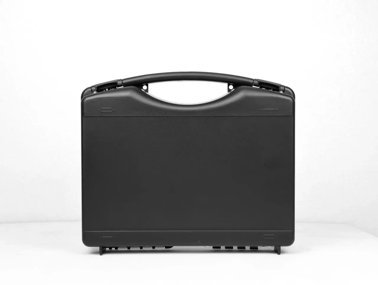
Platens absorb the surge of packing, so a 1.15 factor lifts 617 tonnes to 710. One frame size up, 800 tonnes covers it. A 650-tonne press falls 60 tonnes short and leaves 0.1 mm of flash along the seal lip, which is exactly where an O-ring has to seat.
Oversizing has its own bill: tie bars 1050 mm apart leave 100 mm of slack around a 900 mm by 850 mm mould and add 40 minutes per changeover, while a 620 mm stack on a press rated from 500 mm needs a spacer that eats 30 mm of ejector stroke.
3. Pick the screw by shot weight
Buyers usually match the screw to tonnage, the second place a specification slips. Capacity drives the choice: 2.5 kg divided by 0.8 calls for 3.1 kg of polystyrene equivalent, and a 65 mm screw delivers 3.6 kg.
Fit an 80 mm screw to an 800-tonne case injection molding machine and nominal shot jumps to 6.0 kg; polypropylene held above 230 degrees for 6 minutes then degrades into yellow streaks while weight scatter widens from 1.5 percent to 3 percent.
Keep length-to-diameter at 22 to 24, compression ratio 2.5, back pressure 6 MPa and 90 rpm. Harder back pressure breaks glass fibres and costs 30 percent of strength. Drying follows the resin: 80 degrees for polypropylene, 4 hours at 100 for glass-filled PA66 to reach 0.15 percent moisture.
4. Mould and cycle follow water lines and ejection
Cycle time is where a case injection molding machine earns its keep, and 72 seconds is built rather than guessed: 8 seconds of clamp movement, 12 of hold, 32 of cooling and 5 for removal, with plasticising overlapped. Cooling is the only stage with slack, and cooling belongs to the water circuit.
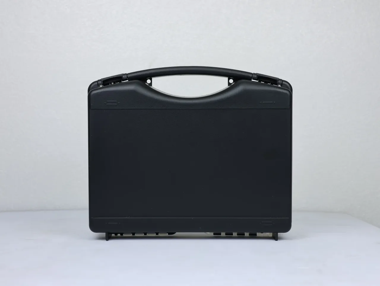
A core 180 mm deep needs its own circuit. Fixed-half water alone lets the core climb to 90 degrees, the skins shrink 0.8 mm apart, and the bottom corners lift until half of them miss a bench.
Hold 28 degrees with a 3 degree rise and 60 litres per minute per cavity; at an 8 degree rise, two parts from one shot differ by 0.06 kg and operators chase hold pressure all shift.
Allow 1.6 percent shrink, so a 480 mm cavity is cut at 487.7 mm. Draft stays at 1.5 degrees; below 1 degree in the deep section, ejection climbs from 11 tonnes to 18 and prints 0.3 mm bumps where a liner has to sit.
5. Turning four numbers into a trial checklist
On one sheet they become a checklist ticked before a case injection molding machine is accepted.
| Check | Target | Tolerance |
|---|---|---|
| Consecutive shots | 30 | No stop |
| First-part weight | 2.2 kg | 2 percent |
| Cavity length | 480 mm | 0.3 mm |
| Cycle time | 72 s | 4 s |
The skipped item is usually the consecutive count: watch weight from shot 25 to 30, where a short screw shows first. Time the cycle by stopwatch rather than the screen, since a 4 second gap to reality is normal. Log measured tonnage too, because platens deliver about 90 percent of nominal and 760 tonnes holding 710 leaves 7 percent.
Conclusion
Sequence matters: area sets tonnage, shot weight sets the screw, cooling sets the cycle, ejection sets the tool. Swap two and the early saving returns doubled. Every millimetre on the drawing ends up as a figure on a plate, which is the whole art of specifying a case injection molding machine.
This article discusses only the container (case body) side of specifications and design intent, and does not cover any handling, loading or use of the contents.
Related Reading
- How the press clamps and plastifies
- Lubrication and temperature intervals
- Cavity volume and load ratings for ammunition boxes
- Latch and seal-groove layout on chests
- Wall thickness and ribs for protective cases
Related Products
- 8 Series — Gun Cases; Military Equipment Cases; Camera Equipment Cases; Drone Cases; Watch Cases; Knife Cases; First Aid Cases; Electronics Equipment Cases
- WL8-2812 PP Gun Case — model WL8-2812
- All protective cases and toolboxes: 7 series, 158 models