

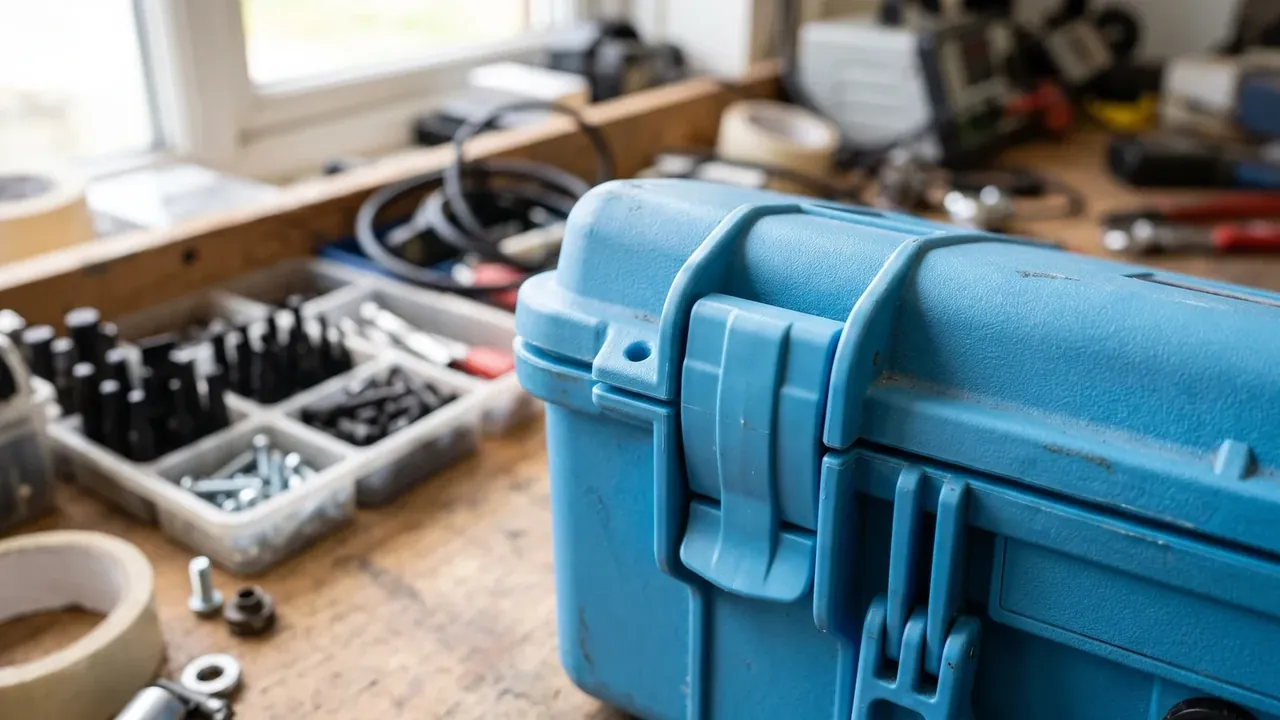
Quick answer: A Tool Box Lid is specified as a dimension chain that starts at the cavity. Cavity depth sets inner depth, inner depth sets body height, body height stacks into pitch. Wall 2.8 mm at plus or minus 0.15 mm, latches sized by case length, gasket compression near 30 percent, load expressed as pressure.
Table of contents
- Where the Tool Box Lid Dimension Chain Starts
- Wall Thickness and Tolerance on Moulded Lids
- Hinge and Latch Specification Points
- Gasket Compression and Closing Force
- Load Rating and Stacking Calculation
- FAQ
1. Where the Tool Box Lid Dimension Chain Starts
A Tool Box Lid drawing usually arrives with cavity dimensions only. The 480 by 320 by 180 mm figure is clear internal space, with three dimensions hanging off it: inner depth, body height, stacking pitch.
| Dimension | Nominal | Tolerance |
|---|---|---|
| Cavity length by width | 480 by 320 mm | plus or minus 1.0 |
| Lid inner depth | 45 mm | plus or minus 0.6 |
| Lid body height | 38 mm | plus or minus 0.8 |
| Stacking pitch | 8 mm | plus or minus 0.3 |
Inner depth runs 45 mm from gasket face inward and sets rib depth near a quarter of it, so 45 mm pairs with 10 to 12 mm ribs. Body height is 38 mm at the rim, and four cases high drift 3.2 mm, so rack levels round up in 5 mm steps.
2. Wall Thickness and Tolerance on Moulded Lids
A 2.8 mm nominal wall with plus or minus 0.15 mm suits a lid of one square metre projected area. The crown centre measures 2.55 to 2.65 mm, ribs root at 3.4 mm where two flow fronts meet, and the 6 to 8 second cooling gap seeds a slight warp.
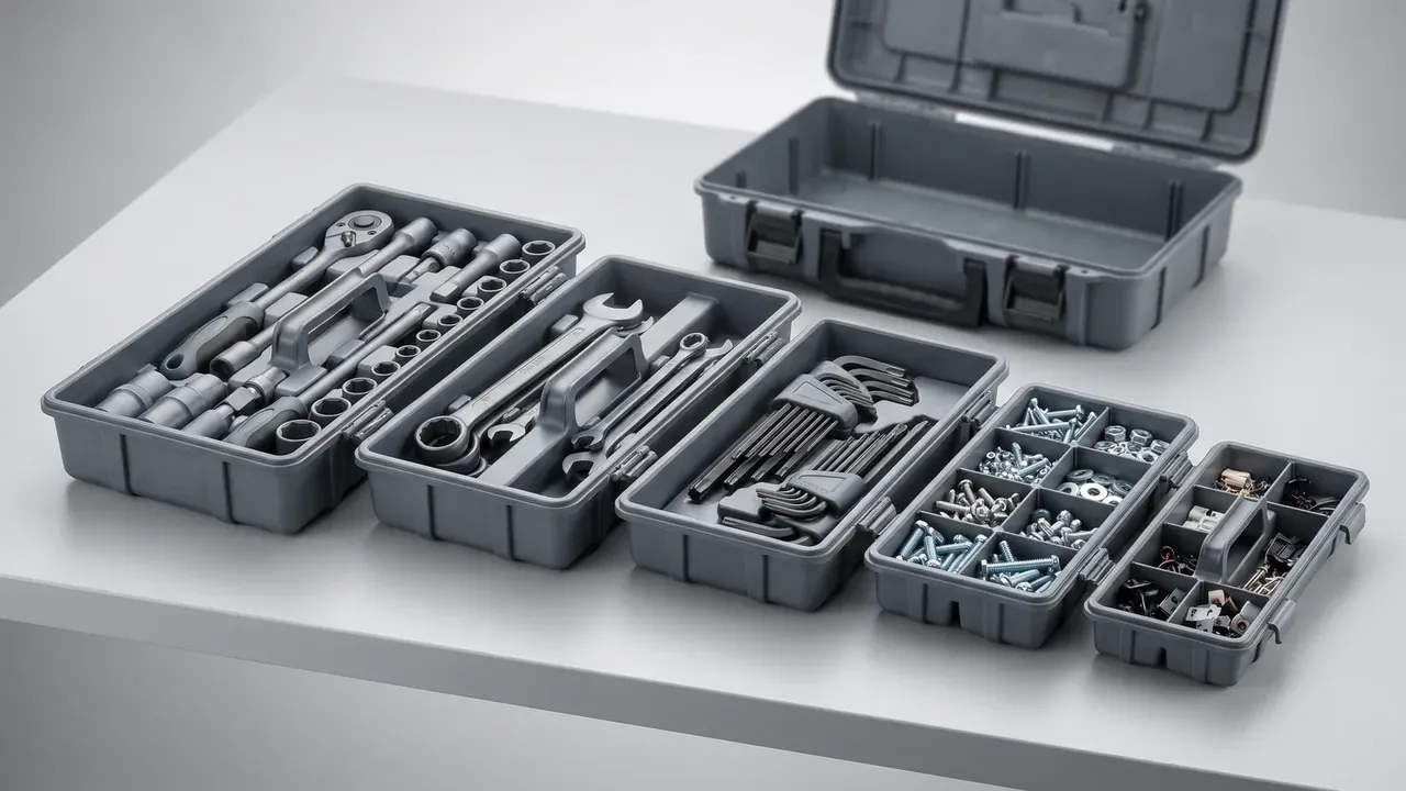
Thickness is gauged at five points, four corners and centre, and the minimum must hold 90 percent of nominal, or 2.52 mm; below that a drop test opens a crack at the thin point. Polypropylene shrinks 1.4 to 1.8 percent, giving 0.9 mm of diagonal error over a metre, and draft needs one degree per 100 mm or ribs whiten on ejection.
3. Hinge and Latch Specification Points
The pin is 4.0 mm at h9 in a 4.1 mm H10 bore, 0.05 to 0.10 mm of clearance. Tighter and it seizes at minus ten Celsius; looser and the lid rocks until the rims mismatch.
Latch count follows length rather than volume: two to 400 mm, three from 400 to 600 mm, four beyond. Gasket reaction lifts the seal between latches, and spacing past 250 mm is where leakage starts. Seats stay 3.5 mm thick, and two 180 N latches give 360 N against 190 N of seal reaction.
4. Gasket Compression and Closing Force
The cord sits 6.0 mm free in a 4.2 mm groove, so compression is 1.8 mm, or 30 percent. Below 20 percent it never beds; above 40 percent it flattens and the latches will not close. Groove width is cord width plus 0.2 mm, depth 0.70 of free height.
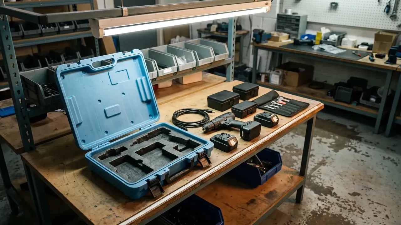
Closing force scales at about 12 N per 100 mm of perimeter, so a 1600 mm lid needs 190 N, the push of 19 kg with one hand.
5. Load Rating and Stacking Calculation
Crown load becomes pressure before rib depth is chosen. A 600 by 400 mm crown covers 0.24 square metres, so 60 kg on top works out at 2.5 kPa.
Deflection is capped at one two-hundredth of span, 2.4 mm over 480 mm. Ribs 10 mm deep at 120 mm centres hold about 1.6 mm at 2.5 kPa; at 6 mm the figure jumps to 3.1 mm. Point loads are separate: 80 kg on a 100 by 100 mm block raises local stress more than tenfold.
| Stack height | Top load | Deflection limit | Rib depth | Corner guards |
|---|---|---|---|---|
| 3 high | 60 kg | 2.4 mm | 10 mm | Advised |
| 4 high | 80 kg | 2.0 mm | 12 mm | Required |
| 5 high or more | 100 kg | 2.0 mm | 14 mm | Required |
Conclusion
Specify a Tool Box Lid by drawing the dimension chain first and arguing numbers later: cavity sets inner depth, inner depth sets body height, body height stacks into pitch. Wall and draft are the moulding floor, pin and latch spacing the life floor, compression and closing force the feel floor. That is what makes a Tool Box Lid repeatable batch to batch.
This article discusses only the container (case body) side of specifications and design intent, and does not cover any handling, loading or use of the contents.
Related Reading
- How a Tool Box Lid is built and the three lid types
- Material and shrinkage differences in plastic tool boxes
- Tracing Tool Box Lid warp and latch failure
- Tool box frame and compartment layout
Related Products
- 8 Series — Gun Cases; Military Equipment Cases; Camera Equipment Cases; Drone Cases; Watch Cases; Knife Cases; First Aid Cases; Electronics Equipment Cases
- WL8-2812 PP Gun Case — model WL8-2812
- All protective cases and toolboxes: 7 series, 158 models