

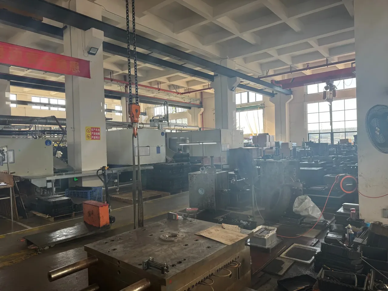
Quick answer: A Toolbox Mold with two cavities runs a 60 s cycle at 720 parts a day. A 45 mm slide stroke at 18 degrees keeps each handle recess clean.
Table of contents
- Cavity Count and Output Arithmetic for a Toolbox Mold
- Slide Core Structure and Stroke
- Cooling Circuit Layout and Temperature Spread
- Vent Locations and Trapped Air
- Trial Run Acceptance and the Mold File
- FAQ
1. Cavity Count and Output Arithmetic for a Toolbox Mold
Extra impressions are not free capacity. Each consumes cavity steel, slide work and water line, then more clamp force from the press. A 460×320×230 mm case projects 0.147 m², so a two-cavity Toolbox Mold sits at 0.29 m² and a four-cavity layout at 0.59 m².
Tool cost rises below the linear rate: 1.0 at one impression, about 1.6 at two, 2.6 at four; money lands in blocks, slides and circuits rather than the base.
| Cavity count | Tool cost | Cycle | Parts per shift | Break-even |
|---|---|---|---|---|
| 1 | 1.0 | 55 s | 523 | none |
| 2 | 1.6 | 60 s | 960 | 37,000 |
| 4 | 2.6 | 68 s | 1,694 | 71,000 |
Four cavities yield 1,694 parts a shift against 960 from two, a ratio of 1.76 rather than 2, since the cycle stretches to 68 s and a thick case spends most of it freezing. The runner must split in a symmetrical H, or the far cavity short-shots while the near one flashes.
Under 37,000 parts across tool life, two cavities stay cheaper.
2. Slide Core Structure and Stroke
On a Toolbox Mold the handle recess, latch seat and lid lip stand on the side wall and block the opening direction, so a slide pulls them sideways. At 18 degrees the angular pin shifts the slide 0.325 mm per 1 mm of platen travel, tying stroke to opening distance.
An undercut 30 mm deep takes a 45 mm stroke, leaving 15 mm, a third of the travel. Reset clearance, pin-to-bore fit and thermal growth eat 3 mm to 5 mm of that margin. Too little shows as scuffing at the recess root, a pale streak that polishes out once and returns.
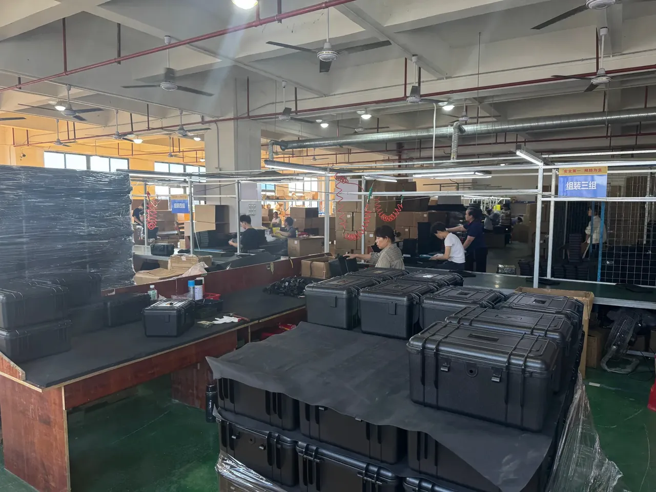
A 45 mm lateral move needs 139 mm of opening stroke, from 45 divided by tan 18 degrees; with less, the slide half retracts and the part will not eject.
| Slide stroke | Opening stroke | Undercut covered | Body length |
|---|---|---|---|
| 30 mm | 92 mm | 22 mm | 90 mm |
| 45 mm | 139 mm | 32 mm | 135 mm |
| 60 mm | 185 mm | 45 mm | 180 mm |
Body length runs at three times the stroke, so 135 mm is the floor; a shorter guided face lets the slide yaw and the wear plate step. The locking block is cut 2 to 3 degrees steeper, so a Toolbox Mold on 18 degrees carries a 20 or 21 degree wedge.
3. Cooling Circuit Layout and Temperature Spread
A two-cavity Toolbox Mold carries eight circuits: two in the cavity plate, two in the core, two in each slide. Slides get their own water because those inserts form the thick collar around the handle recess, and tying them to a cavity line pulls the cavity face down.
Drill diameter is 10 mm, centre line 15 mm to 20 mm off the cavity face, pitch 30 mm to 50 mm: 1.5 to 2 and 3 to 5 diameters.
Water has to run turbulent. At 0.8 m/s a 10 mm channel carries about 4 L/min and puts Reynolds past 10,000; below 0.5 m/s the heat transfer coefficient drops by a third and the 60 s cycle stops holding.
An inlet-to-outlet spread inside 3 °C means clear passages and enough flow. Five degrees says filter or scale, not a set point to adjust.
| Circuit spread | Outlet at 20 °C | Reading | Action |
|---|---|---|---|
| 1 °C | 21 °C | ample | log as baseline |
| 3 °C | 23 °C | at the limit | check filter |
| 5 °C | 25 °C | starved | flush, verify pump |
Cooling takes 60 to 70 percent of the cycle, 36 s to 42 s of every 60 s. A 3 °C gap between cavity and core makes the box bow toward the cooler half.
4. Vent Locations and Trapped Air
Vents follow the last place to fill, not the outline. On a Toolbox Mold those are the four base corners and the weld lines flanking the handle recess.
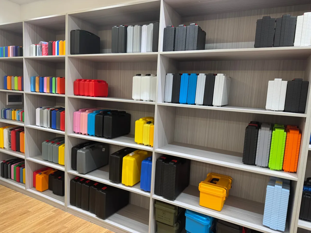
Short shots at 80, 90 and 95 percent show where the front stops; the last position is where the vent belongs.
Vent depth is 0.02 mm, land 0.5 mm to 1.5 mm, relief 0.3 mm to 0.5 mm to atmosphere. Burn falls as the gap opens while flash climbs; the curves cross near 0.021 mm, and past that flash gains faster.
Air under a slide is easy to miss. Closed, slide and cavity wall enclose a corner with no exit, and the side wall scorches behind the recess; a vent on the wear face clears it, or 0.03 mm to 0.05 mm clearance.
5. Trial Run Acceptance and the Mold File
Trials run 30, 70 and 200 pieces, 300 in total: fill first, then dimensions, then repeatability of slide and core pull.
The rejection line is fixed: scuffing or a gas burn inside those 300 blocks release. Read scuffing on the wall the core leaves, burns at the base corners, both under raking light.
Circuits are pressure-tested at 1.5 times working pressure for 30 minutes, cold and again at 60 °C.
The Toolbox Mold file records circuit flow, the 45 mm stroke at 18 degrees, vent coordinates, the trial curve and 30 retained samples. A repair that grinds 0.01 mm changes groove depth, and memory will not restore it.
Conclusion
Cavity count first, stroke second, circuits last. Two cavities on a 60 s cycle, a 45 mm stroke behind an 18 degree pin and eight circuits inside 3 °C make the process repeatable. Run 300 pieces clean and the Toolbox Mold can be signed off; skip one number and the defects repeat.
Related Reading
- what a case mold costs
- P20 versus 718 mold steel
- trial run guide for case molds
- what drives case mold life
Related Products
- 8 Series — Gun Cases; Military Equipment Cases; Camera Equipment Cases; Drone Cases; Watch Cases; Knife Cases; First Aid Cases; Electronics Equipment Cases
- WL8-2812 PP Gun Case — model WL8-2812
- All protective cases and toolboxes: 7 series, 158 models