

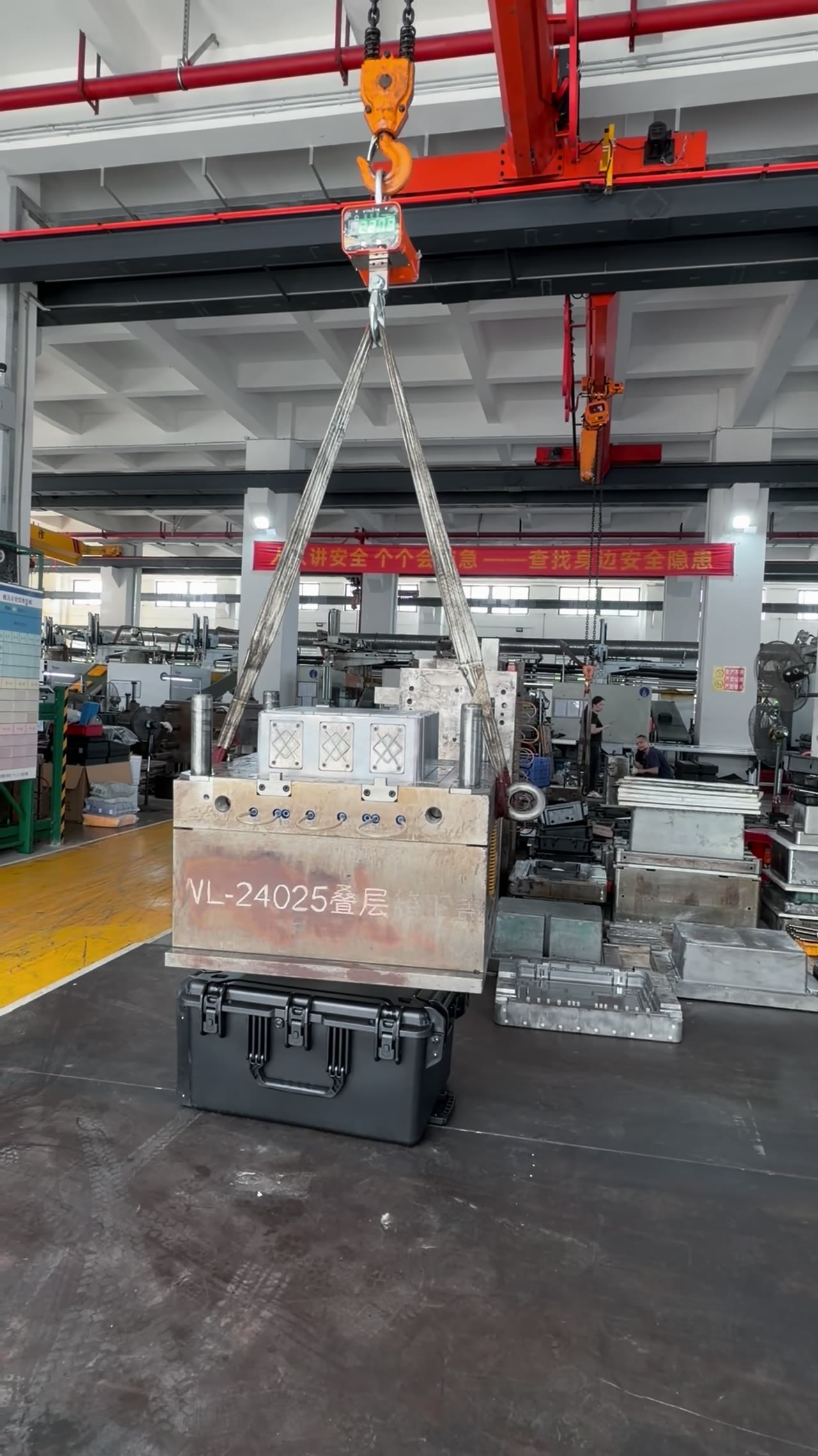
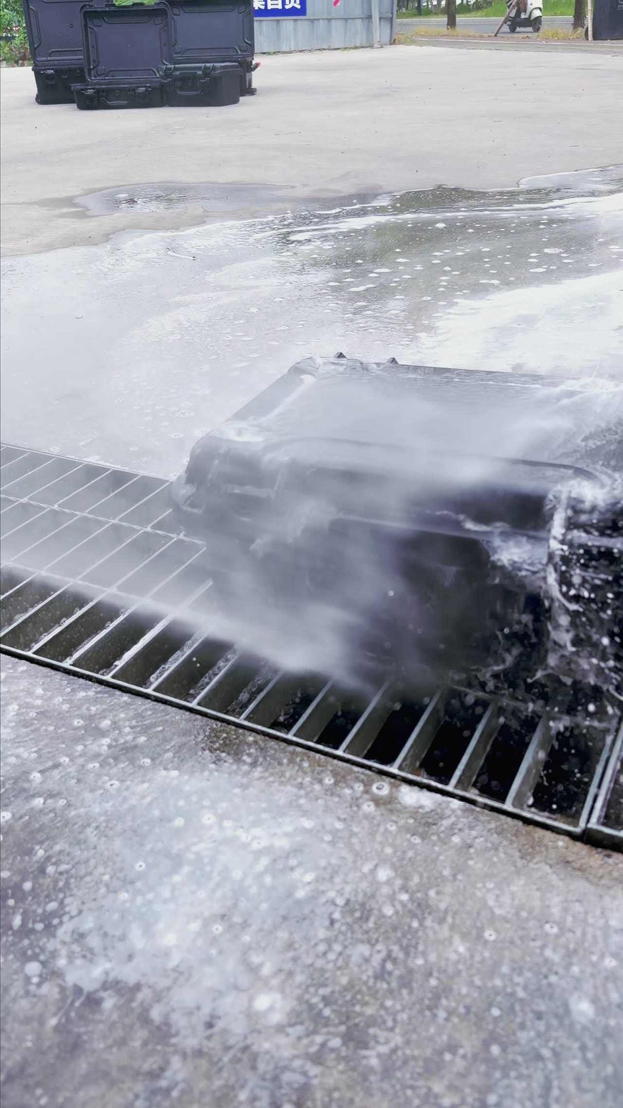
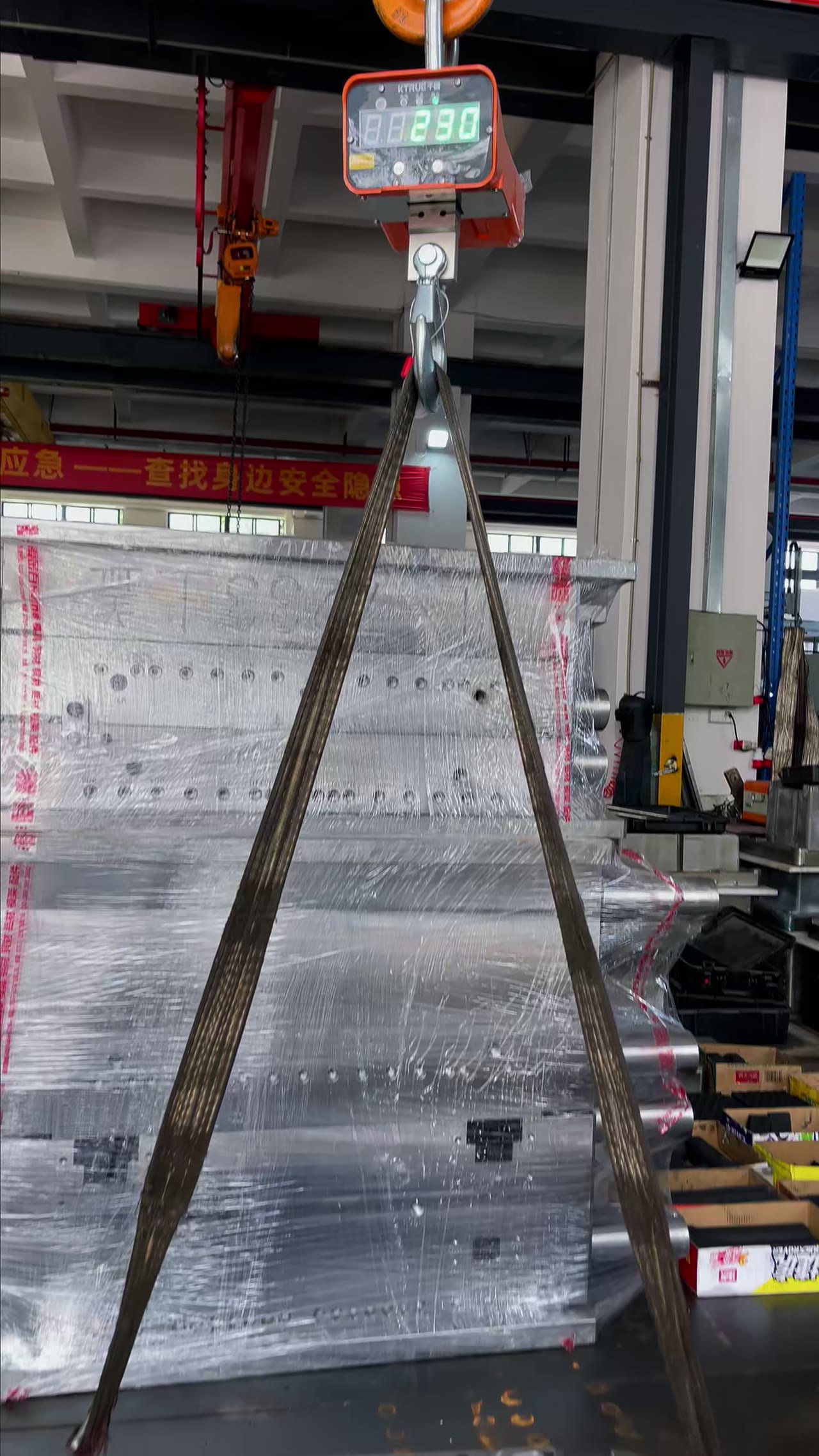
1620 kg Load Challenge: What Was Recorded
The number on the display is not a property of the case. It is a property of the rig. Platen size, support span, backing plate thickness, loading rate, hold time and eccentricity all feed into it, and change any one of them and the same box reads differently: widen the platen and pressure per unit area collapses, slide the supports out and deflection climbs with the cube of span. This page stays on that geometry problem, because a load figure quoted without its rig is not something you can carry over to your own bench.
01Platen area rewrites the reading before the case ever moves
Swap the platen and the result changes. Going from 300 mm to 800 mm on a side multiplies contact area by roughly seven and divides contact pressure by the same factor. A small platen punches a local dent; a large one bends the whole lid as a plate. In this batch the contact pressure sat between 0.6 N and 2.4 N on each square millimetre.
If the platen edge sits inside the lid footprint, load stays in the middle and you are measuring local stiffness. If the platen covers the lid completely, load travels out to the walls and you are measuring overall bending. Both get filed as a 1620 kg result, and they answer different questions. Find the platen edge first, then decide whether the number applies to you.
02Move the supports one notch and the reading drops forty percent
Support span runs 400 mm to 1200 mm in this work. Triple the span and deflection does not triple; it climbs with the cube. At 400 mm the base is almost resting on the plate and the dial barely moves. At 1200 mm a long middle section hangs in air and the reading turns ugly fast. Forty percent between two support settings is normal.
The rule: supports go under the ribs that actually contact the ground, not under two scraps of timber. Shift a support 50 mm and that corner slides from simply supported toward cantilever, the near dial jumps and the centre stays put. Publish the span and the support locations or nobody can repeat your run.
03The backing plate bends too, and you must subtract it
A 10 mm to 30 mm backing plate is a loaded part, not a table. A 20 mm timber plate sags 2 mm to 3 mm under 1620 kg, and that sag lands in the ram travel, inflating the case deflection. Thin steel at 10 mm bulges as well, just more evenly, which makes it look like the case is bending when it is the plate.
The test is simple: plate deflection must stay under 10% of case deflection. Press the bare plate once, record its sag, then subtract that from the loaded run. If the subtraction will not come clean, fit a thicker plate or move the supports to where the plate is stiff. Skip the step and the number carries an unknown.
04Rate and hold time shape the middle of the curve
Loading rate spans 1 mm/s to 10 mm/s. Drive it fast and the material has no time to creep, so the reading runs high and the case looks stiffer than it is. Drive it slowly and deflection at the same load grows by 10% to 20%. Both rates are legitimate, but pick one and stay with it, or you are comparing rates instead of cases.
Hold time runs 60 seconds to 600 seconds, and the number is read at the end of the hold, not when the ram first lands. The gap between a 60 second and a 600 second hold is usually 0.5 mm to 2 mm, and that gap is creep. The first second makes the best footage and the worst data.
05Fifty millimetres off centre splits the two dials
Eccentricity of 0 mm to 50 mm is enough. Push the ram 50 mm off the geometric centre and reaction rises on the near support and falls on the far one; the two dials can differ by half the mean. The case is not asymmetric, the loading is. Flip the offset and the readings swap ends, which is the giveaway.
Unloading rebound lands at 1 mm to 4 mm. Read it 60 seconds after release: inside that band, most of the movement was elastic. Above 4 mm, stop watching the peak and go look at what remains. The clip records a procedure; usability is settled by the plate size, span, rate, hold time and offset written in the formal record.
| Platen edge length | 300–800 mm |
|---|---|
| Contact pressure | 0.6–2.4 N per square millimetre |
| Loading rate | 1–10 mm/s |
| Hold time | 60–600 seconds |
| Backing plate thickness | 10–30 mm |
| Support span | 400–1200 mm |
| Load eccentricity | 0–50 mm |
| Unloading rebound | 1–4 mm |
FAQ
Is 1620 kg the rated load of this case?
No. It is the total applied in one run. The reading also depends on platen size, span, plate thickness, rate and hold time, so a different rig gives a different figure. A rating has to be established by the maker on fixed tooling. Treat the clip as a record, not a specification.
Why do two identical cases read differently?
Compare the rig first: platen size, span, plate thickness, rate, hold time, offset. Any one of the six differing removes comparability. Only when all six match does the case itself become a suspect. Most disputes about identical cases end at the support span.
How big should the platen be?
Choose by the question. For local crush resistance, use a small platen around 300 mm on a side. For overall bending, use one that covers the whole bearing face. Running both is safest; running one means the platen size has to appear next to the figure.
When should rebound be read?
Sixty seconds after release. Earlier and the material is still springing back, so the number runs low. Later and creep recovery mixes in, so it runs high. Fix 60 seconds across a batch and the runs compare. For long-term recovery, add 2 h and 24 h points.