


An ADAS sensor transport case is a dedicated protective container for moving and storing LiDAR, vehicle cameras, millimeter-wave radar, ultrasonic sensors and their calibration tooling in autonomous-driving development, testing and production. Its core value is not only impact protection but holding three lines at once: keeping optical windows and lenses free of contamination and scratches, preserving sensor attitude and calibration state, and preventing latent failures from ESD and moisture. Compared with an ordinary instrument case, an ADAS sensor transport case carries high-value, high-precision optoelectronic equipment that is sensitive to cleanliness and attitude. One knock can produce abnormal point clouds, one fingerprint or smear can blur imaging, and one over-temperature or moisture event can drift circuit performance, yet these faults often surface only at the vehicle calibration stage, where diagnosis is extremely expensive. This article covers the selection and design of autonomous-driving sensor cases, LiDAR transport cases, ADAS equipment cases, in-vehicle sensor cases and perception equipment cases, breaking down protection ratings (IP / GB/T 4208 / MIL-STD-810H / ISTA), LiDAR fixation and window protection, camera and radar protection, calibration target transport, ESD, moisture and cleanliness, material selection, impact, vibration and calibration accuracy, temperature control and battery safety, procurement and acceptance, and common mistakes, with tables that can be used directly in tenders and acceptance. The goal is to help OEMs, Tier 1 suppliers, autonomous-driving companies and testing organizations cut sensor damage rates and calibration rework.
Readers who need the fundamentals of cases and liners should first review Plastic Protective Cases: Material and Structure and Cushion Liner and Custom Cutting Design. For vibration isolation and temperature control of precision instruments see Precision Instrument Cases, and for static and shielding see Anti-Static and EMI Shielding Solutions and Anti-Static Electronic Component Protection.
What Is an ADAS Sensor Transport Case
An ADAS sensor transport case, also called a LiDAR transport case, ADAS equipment case, in-vehicle sensor case or perception equipment case, is a professional protective container for sensor circulation and storage in the intelligent-driving supply chain. The difference from an ordinary instrument case is the payload profile: an ordinary instrument case protects a single device, while a sensor transport case often carries several sensors, harnesses, brackets, calibration targets and tooling at once, and among them LiDAR contains high-speed rotating or solid-state optical structures, cameras contain precision lens groups, and millimeter-wave radar contains high-frequency circuits and antenna arrays, each sensitive to shock, cleanliness, static or thermal drift.
In form, an ADAS sensor transport case usually consists of a rigid shell, a custom liner, independent compartments and a latch system. The shell provides impact resistance, dust and water protection and stackability; the custom liner is cut to the sensor outline and optical window orientation to give location and clearance; independent compartments separate sensors and tooling to prevent crushing and contamination; and the latch system keeps everything in place during transport. Common options include a handle or casters, a transparent window, a dissipative surface layer, a desiccant pocket, a temperature and humidity logger position, and a numbering or QR code position for traceability.
Typical users include intelligent-driving research and test departments at vehicle OEMs, Tier 1 sensor and domain controller suppliers, autonomous-driving algorithm companies and road test teams, testing and certification bodies and third-party proving grounds, and after-sales and rental departments of sensor manufacturers. Wherever sensors must move from a laboratory, warehouse or test workshop to a bench or vehicle while preserving calibration state, that is the application boundary for an ADAS sensor transport case.
Fragile Points of LiDAR and In-Vehicle Sensors
The first fragile point is the optical window and lens. The optical window of a LiDAR and the lens of a camera are precision optical surfaces, and fingerprints, oil, dust and scratches directly cause missing point clouds or blurred imaging, while improper cleaning can cause permanent damage. The second is mechanical and optical alignment. Mechanical LiDAR contains rotating parts and bearings, solid-state LiDAR contains precision optical elements, and cameras contain lens groups and focus mechanisms, so a drop or sustained vibration can disturb internal alignment and cause calibration drift.
The third fragile point is static and voltage sensitivity. The laser driver circuit of a LiDAR, the image sensor of a camera and the high-frequency chip of a millimeter-wave radar are all ESD-sensitive devices, and a discharge can cause latent damage that appears as increased dark current, reduced sensitivity or intermittent data faults. The fourth is temperature and humidity with condensation. Optical parts condense and fog easily in high humidity with large temperature differences, causing imaging faults, while over-temperature can drift electronic performance or deform plastic parts. The fifth is connectors and harnesses. Sensor connector pins are dense and fragile, and excessive bending or pulling of a harness causes poor contact or an open circuit that only appears after installation.
The common conclusion from these fragile points is that an ADAS sensor transport case should be engineered as a transport system for precision optoelectronic parts: define the sensor list, optical window orientation and calibration state requirements first, then decide the fixation method, clearance structure, cleanliness and static control, and finally close the loop with transport validation and records. Ordering a case by size and comparing only price usually costs far more later in calibration rework.
Protection Ratings and Referenced Standards (IP / GB/T 4208 / MIL-STD-810H / ISTA)
The protection rating is the foundation of the program. IP rating is judged per IEC 60529 and GB/T 4208: the first digit denotes dust protection from 1 to 6 and the second denotes water protection from 1 to 8. A sensor transport case usually requires at least IP65, meaning fully dust-tight and resistant to low-pressure water jets, and IP67 should be used for rainy-season road testing, wading tests or marine shipping, meaning fully dust-tight and able to survive immersion at 1 meter for 30 minutes. For optical parts the fully dust-tight part of the rating matters most, because fine dust settling on a window immediately affects imaging.
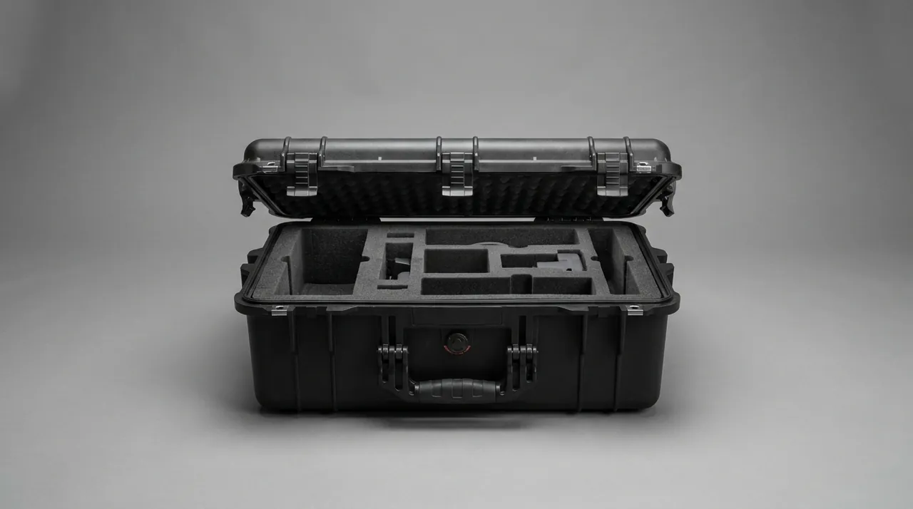
Mechanical and environmental validation can reference MIL-STD-810H: drop (Method 516.8), random vibration (Method 514.8), temperature-humidity cycling (Method 507.6), salt fog (Method 509.6) and low pressure (Method 500.6) correspond to handling drops, road and bench vibration, cross-climate transport, coastal and winter road salt, and high-altitude or air transport. For vehicle road testing and intercity transport, the ISTA series is recommended, for example ISTA 3A for LTL shipping, for whole-package validation. Flame retardancy is rated per UL94, commonly targeting V-0 or V-1, and impact can be described on the IK scale, typically 0.5 to 20 joules.
| Transport scenario | Suggested IP | Suggested methods | Key focus |
|---|---|---|---|
| --- | --- | --- | --- |
| In-plant bench circulation | IP54 to IP65 | Drop, stacking | Location and clearance |
| Intercity road test transport | IP65 | Random vibration, ISTA 3A | Vibration and fixation |
| Rainy season and wading tests | IP67 | Dust, water | Window cleanliness and sealing |
| High altitude and air freight | IP67 | Low pressure, drop | Sealing and pressure equalization |
| Coastal and winter roads | IP67 | Salt fog, temperature-humidity cycling | Corrosion and condensation |
| Export by sea | IP67 | Salt fog, temperature-humidity cycling | Long-term moisture protection |
LiDAR Transport Fixation and Window Protection
LiDAR is one of the most demanding items in the sensor set. Fixation should achieve three-point location, surface-contact support and full clearance of the optical window. The liner is cut around the LiDAR base and mounting flange to form a three-point location so the unit is not held by a single face, the body is supported on high-density EVA over a contact area so point loads cannot press the housing, and the window area must be fully clear with no material contact, with a dedicated window cover fitted and a finger recess for removal.
There are three disciplines for window protection. First, never touch the optical window with bare hands, and wear powder-free gloves when handling. Second, confirm the window cover is fitted and itself clean and dust-free before packing. Third, never place materials that generate dust or debris inside the case, such as low-density polyethylene foam crumb, and use a non-shedding high-density EVA or equivalent liner material. For mechanical LiDAR, avoid long periods upside down or on its side, which can redistribute bearing lubricant, and for high-speed models lock or secure the rotating assembly as required by the manufacturer.
For the housing and mounting face, build anti-rotation and anti-shift features into the liner so the unit cannot rotate against the liner during transport and pull on the harness. If the LiDAR must travel with its bracket, fix the bracket rigidly in a separate compartment so it cannot swing and strike the sensor body. For related vibration isolation and clearance practice, see the thinking in Precision Instrument Cases.
Camera, mmWave Radar and Ultrasonic Sensor Protection
The heart of a camera is the lens group and image sensor. The protection focus is a clearly defined lens orientation, no contact between the optical surface and any material, and avoidance of prolonged direct strong light. The liner should be cut along the optical axis so the lens surface is suspended, and if contact is unavoidable, use a clean soft material with controlled pressure. For modules with active focus or optical stabilization, avoid sustained vibration and consider locking the mechanism during transport as the manufacturer requires.
The heart of a millimeter-wave radar is the antenna array and high-frequency circuit. The protection focus is avoiding metal obstruction and deformation, avoiding static, and preventing connector stress. If the radome has a coating or a special surface, it must not rub against rough material, and connectors should be capped to prevent pin deformation and oxidation. The heart of an ultrasonic sensor is the diaphragm and housing; because pressure on the diaphragm can change the frequency response, the units must not be stacked under load and should be stored upright in independent compartments.
Harness and connector protection matters just as much. Coil harnesses above the minimum bend radius, give connectors independent pockets so the mating face is not contaminated, and avoid sharp bends on high-frequency coaxial cable that would change impedance. If sensors must remain powered or connected during transport, reserve cable routing and connector positions in the liner so cables cannot tangle with the sensors and take load.
Carrying Calibration Targets and Tooling
Calibration is a key step after sensor installation, and calibration targets and tooling are often transported together with the sensors. Common calibration items include calibration boards and targets, corner reflectors, reflective panels and alignment fixtures. These items are sensitive to geometric accuracy: once a target deforms or is contaminated, the calibration result carries a systematic error, and that error is easily misread as a sensor fault.
Three rules apply to carrying them. First, lay targets flat or fix them in the designed attitude so they cannot deform under load. Second, the reflective or patterned face must not rub against any material, so isolate it with lint-free paper and fit a protective cover. Third, keep tooling and fixtures in a separate compartment so they cannot knock against sensors. For large calibration boards, use split transport, placing the main item in the lower level and accessories in the upper tray, or use a dedicated flat case.
When targets and sensors travel in the same case, mark the case exterior clearly with the contents and a precision optical parts, no heavy load warning, and state part numbers and quantities on the checklist so the vehicle installation team can verify quickly. For calibration kits that travel repeatedly between sites, keep one file per case recording usage count and lending history, and replace targets that have deformed or become contaminated.
ESD, Moisture and Cleanliness Requirements
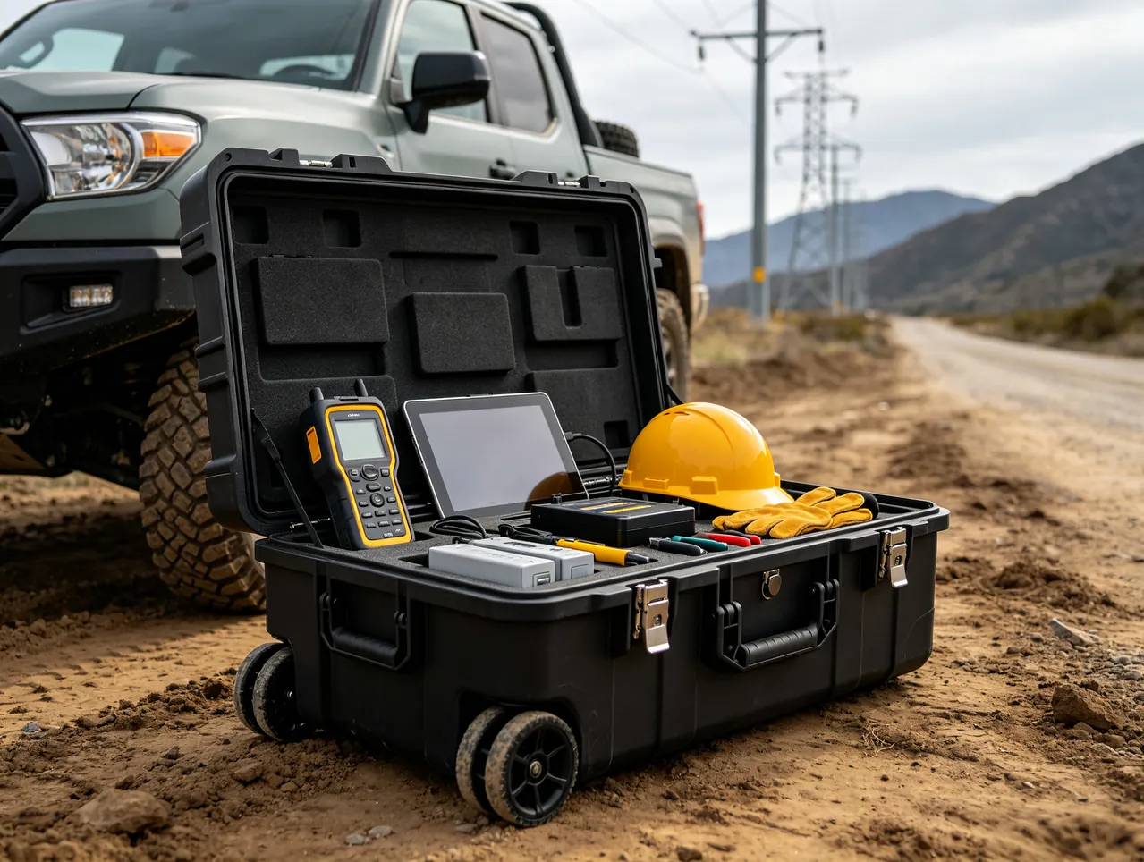
ESD control is a firm requirement for sensor transport. Compartments containing image sensors, laser driver circuits and high-frequency chips should use a conductive or dissipative liner with a grounding terminal reserved on the case, and sensors should be bagged in anti-static or shielding bags before going into the liner. Wear an anti-static wrist strap during work and avoid repeatedly rubbing the case in a dry environment or on synthetic carpet. The relevant standard thinking is in the IEC 61340 series, and for high-frequency modules that need EMI shielding, evaluate an added shielding layer or an aluminum case as described in Anti-Static and EMI Shielding Solutions.
For moisture, condensation and fogging of optical parts is a common fault source. Place desiccant inside the case with a humidity indicator card and keep the case at IP65 or above so external moisture cannot enter; for cross-climate transport or marine shipping, add a humidity logger and check the curve on arrival. Before moving from a cold environment into a warm room, let the case equalize inside before opening the lid, avoiding condensation from a rapid temperature difference. For models with high cleanliness requirements, pack inside a clean room.
For cleanliness, the liner material must be non-shedding and non-dusting, avoiding foam that crumbles or powders easily, and the case must not store items that generate dust. Reusable liners should be cleaned and inspected periodically, and replaced as soon as wear produces crumbs so a long-serving liner does not become a contamination source. For high-cleanliness transport of semiconductor and wafer items, see Wafer and Semiconductor Part Transport Solutions.
Shell Material and Structure Selection
The shell material decides weight, rigidity, cleanability and cost. A rotomolded case is made in one piece from LLDPE with generous wall thickness, no weld seam and excellent impact and weather resistance, suited to large sensor groups and calibration kits. An injection-molded case is molded from PP, ABS or PC with a thin wall, tight precision, a clean appearance and low cost, suited to mid and small sensors and modules. An aluminum case offers high strength, good rigidity, heat dissipation and EMI shielding, suited to high-frequency modules and precision parts that need shielding and cleanliness, but it costs more and resists dents less well than rotomolding.
| Material route | Advantages | Limits | Typical fit |
|---|---|---|---|
| --- | --- | --- | --- |
| Rotomolded | Impact and weather resistant, can be large | Higher self-weight | Large radar groups, calibration kits |
| Injection-molded | Light, precise, low cost | Limited load and size | Cameras, mmWave radar |
| Aluminum | Rigid, can shield and dissipate | Higher cost, dents | High-frequency modules, precision parts |
| Sheet metal plus liner | Customizable, rack mountable | Sealing depends on design | Fixed laboratory stations |
Screen first on five items, namely total sensor weight, maximum size, transport mode, whether shielding is needed and the cleanliness class, then review with total cost of ownership. For most teams the sensible configuration is rotomolding or injection molding for the bulk and aluminum for precision and high-frequency items. For general material and liner methods see Plastic Protective Cases: Material and Structure.
Impact, Vibration and Calibration Accuracy Retention
Calibration accuracy is the final acceptance test for sensor transport. Impact and vibration affect accuracy through two paths: directly causing mechanical deformation or optical element displacement, and over time loosening fasteners or collapsing the liner so the sensor slowly migrates inside the case. Transport validation therefore must not stop at one drop test but cover random vibration and the accumulated effect of repeated handling.
Three measures are recommended. First, fixation before cushioning: make sure the sensor cannot move inside the case, then use the liner to absorb and reduce transmitted impact. Simply adding thicker cushioning without fixation can allow a secondary impact that is worse than the original. Second, control the natural frequency: the liner and sensor combination should avoid being close to the dominant vibration frequency of the vehicle or bench, so resonance amplification is reduced, adjusting liner density or adding restraint where necessary. Third, confirm calibration after transport: for critical sensors, run a quick calibration check or static inspection before installation to prove that transport introduced no drift, and record the result.

For teams doing intercity road testing, add a shock label and tilt label to the outer box and read them on arrival to judge whether an over-limit event occurred. For high-value sensors, a temperature, humidity and shock logger produces an auditable transport file.
Temperature Control and Hot/Cold Transport
Temperature affects sensors in two ways: the operating point of electronic components drifts, and optical parts condense and fog. Most sensors only need to avoid extremes rather than hold a precise set point, in which case an insulating liner plus a temperature logger delivers traceability. Where a low-temperature environment must maintain standby readiness, or a high-temperature environment risks softening plastic parts, an active temperature-controlled case with cooling or heating is needed.
| Temperature scheme | Stability | Duration | Main limit |
|---|---|---|---|
| --- | --- | --- | --- |
| Insulating liner | Medium | A few hours | Strongly affected by ambient temperature |
| Insulating liner plus phase-change material | Good | 12 to 48 hours | Requires pre-conditioning and sizing |
| Active temperature-controlled case | High | Long duration | Needs power, heavy |
| Ambient case plus logger | Low | Unlimited | Records but does not control |
Whichever scheme is used, avoid rapid temperature swings: after removal from a cold environment, let the case equalize while closed before opening the lid, preventing condensation on optical surfaces. For air freight, consider how low pressure affects a sealed case and fit a pressure-equalization valve where needed, and follow the restrictions that apply to lithium battery transport.
Safe Transport of Batteries and Power Modules
Sensor testing often involves power modules, mobile power banks and lithium batteries. Lithium-ion batteries carry a thermal runaway risk in transport, so batteries should be stored in a separate compartment, kept away from metal parts to prevent short circuit, fitted with protective caps or insulation on the terminals, and protected from crushing and puncture. For air transport, follow the lithium battery restrictions such as state of charge and packaging requirements, and mark the case exterior clearly with the battery presence and capacity.
For sensor modules containing batteries, confirm the power is off and the connectors are capped before transport. For recording devices that must stay powered, use an independent power supply and secure it well so vibration cannot pull on cables. For transport thinking on energy storage and charging equipment, see Battery Energy Storage Module Transport Solutions and Charging Module and Power Protection Solutions.
Typical Application Scenarios and Configurations
| Scenario | Recommended configuration | Key point |
|---|---|---|
| --- | --- | --- |
| In-plant bench circulation | Injection case plus EVA liner plus clearance pockets | Light, fast access |
| Intercity road test | Rotomolded case plus independent compartments plus shock labels | Vibration and anti-shift |
| Rainy season wading test | IP67 case plus desiccant and humidity card | Dust and condensation |
| Calibration kit transport | Flat case plus target fixation plus protective covers | Geometric accuracy retained |
| High-value radar transport | Aluminum case plus EVA plus logger | Shielding and traceability |
| Export by sea | IP67 case plus corrosion package | Long-term moisture protection |
| Sensor rental circulation | Standard case plus numbered labels plus checklist | Asset traceability |
Where a domain controller and harness must travel together, use a partitioned case that separates high-value sensors from harnesses and brackets so they cannot crush each other. For more detailed practice on electronic control modules, see Electronic Equipment and Module Protection.
Procurement and Acceptance Checklist
Sensor case procurement is usually tied to an equipment purchase or an R and D project, so technical clauses must be clear and verifiable. The recommended checklist is: first, the sensor and tooling list with dimensions, weights, optical window orientation and quantities as the input to liner design; second, the protection rating and governing standard, GB/T 4208 or IEC 60529, stating whether IP67 is required; third, mechanical and environmental validation requirements, including drop height, random vibration level, and whether ISTA and MIL-STD-810H method numbers are referenced; fourth, ESD requirements such as surface resistance range, grounding terminal and liner type; fifth, cleanliness and material requirements, namely non-shedding, non-dusting and a material class suitable for contact with optical parts; sixth, liner and clearance design, including full window clearance, three-point location and independent compartments; seventh, temperature control and recording, including the insulation scheme, logger position and pressure-equalization valve; eighth, accessories such as handle, casters, protective covers, labels and checklist; and ninth, documents including test reports, material certificates and sampling plan, plus lead time and after-sales terms.
At acceptance, use first-article plus sampling: check the liner fit with sensors, whether the optical window clearance is complete, tongue contact, latch compression and grounding continuity on the first article, then verify the IP rating, representative drop and random vibration items, liner dimensional consistency and a non-shedding material check on sampled units. For projects that must retain calibration accuracy, run a calibration check before and after the transport validation so that data proves no drift was introduced.
Common Mistakes to Avoid
Mistake one: ordering a case by size and ignoring window clearance, when any contact with the optical window can scratch or contaminate it. Mistake two: adding cushioning without fixation, so the sensor suffers a secondary impact inside the case that is worse than the original. Mistake three: ignoring ESD and cleanliness and using ordinary foam, so shedding and static damage the optoelectronic parts at the same time. Mistake four: skipping the post-transport calibration check, so calibration drift is misread as a sensor fault. Mistake five: carrying calibration targets with sensors under load, so target deformation creates a systematic error. Mistake six: mixing batteries with metal parts, creating short-circuit and thermal runaway risk. Mistake seven: ignoring condensation control on cross-climate transport, so the case fogs as soon as it is opened. Mistake eight: keeping no transport record, so damage responsibility cannot be traced. Putting these into the review table prevents most failure scenarios.
JUNZHJIA Customization Capability
JUNZHJIA provides customized and volume supply of sensor transport cases for vehicle OEMs, Tier 1 suppliers, autonomous-driving companies and testing organizations. We machine high-density EVA liners, full optical window clearance structures, three-point locations and independent compartments from the sensor list and window orientation, and support dissipative and conductive surface layers, grounding terminals and EMI shielding options. The shell can follow any of three material routes, namely rotomolding, injection molding and aluminum, and can be supplied with handles, casters, a pressure-equalization valve, temperature, humidity and shock logger positions, and a unified numbering and QR code scheme. We can provide GB/T 4208, MIL-STD-810H and ISTA related test documents and support structural review, sampling and mass production. For teams sharing multiple sensor models, we support a modular program with standard cases and dedicated liners, combining long case reuse with model-specific liners to cut long-term procurement and inventory cost.
Frequently Asked Questions (FAQ)
Question: What is the essential difference between an ADAS sensor transport case and an ordinary instrument case? Answer: The essential difference is the payload profile and the consequence of failure. An ordinary instrument case protects a single device, while a sensor transport case often carries LiDAR, cameras, mmWave radar, harnesses and calibration tooling together, where optical parts are sensitive to cleanliness and attitude, electronic parts are sensitive to static, and calibration items are sensitive to geometric accuracy. A single window contamination or calibration drift usually surfaces only at the vehicle calibration stage, and rework is extremely expensive. A sensor transport case must therefore solve location and clearance, ESD, moisture and condensation control and accuracy retention at the same time.
Question: What matters most when transporting LiDAR? Answer: Three things. First, the optical window must be fully clear with no material contact, a dedicated cover should be fitted, and powder-free gloves must be worn, since bare fingers must never touch the window. Second, fixation must use three-point location with surface-contact support so point loads do not press the housing, while anti-rotation features prevent the unit turning against the liner and pulling on the harness. Third, the liner material must be non-shedding, avoiding foam that crumbles or powders, so dust cannot settle on the window and degrade imaging. Mechanical LiDAR should also not be stored upside down or on its side for long periods, and the rotating assembly should be locked as the manufacturer requires.
Question: Why is a calibration check needed after transport? Answer: Impact and vibration affect calibration accuracy through two paths: directly causing mechanical deformation or optical element displacement, and over time loosening fasteners or collapsing the liner so the sensor slowly migrates inside the case. Neither shows up as obvious damage when the case is opened, but both appear at the vehicle calibration stage as abnormal point clouds or imaging offset and are easily misread as a sensor fault. For critical sensors, run a quick calibration check or static inspection before installation, after transport validation or an intercity road test, so data proves that transport introduced no drift, and record the result.
Question: Should the liner be EVA or another material? Answer: Prefer high-density, non-shedding EVA or an equivalent material, cut to the sensor outline and window orientation to achieve three-point location and surface-contact support. Avoid low-density foam that powders, crumbles or sheds, because crumbs and dust contaminate the optical window and lens. For compartments that need ESD control, use conductive or dissipative EVA with a grounding terminal reserved. Whichever material is chosen, the optical window area must be fully clear, and the liner should be cleaned and inspected periodically, replaced as soon as wear produces crumbs.
Question: How should camera lenses be protected? Answer: Three disciplines. First, the optical surface must not contact any material, so the liner is cut along the optical axis to suspend the lens; if contact is unavoidable, use a clean soft material with controlled pressure. Second, avoid prolonged direct strong light on the lens surface, which can damage coatings and the sensor. Third, confirm the lens cap or protective film is fitted and clean before transport, and never store dust-generating items in the case. For modules with active focus or optical stabilization, consider locking the mechanism as the manufacturer requires and avoid sustained vibration.
Question: How do I prevent static damage during sensor transport? Answer: Compartments containing image sensors, laser driver circuits and high-frequency chips should use a conductive or dissipative liner with a grounding terminal reserved on the case, and sensors should be bagged in anti-static or shielding bags before going into the liner. Wear an anti-static wrist strap during work and avoid repeatedly rubbing the case in a dry environment or on synthetic carpet. The relevant standard thinking is in the IEC 61340 series. For high-frequency modules that need EMI shielding, evaluate an added shielding layer or an aluminum case, and check the continuity between the shielding layer and ground so that poor grounding does not create interference.
Question: Why is condensation control needed for cross-climate transport? Answer: Because fogging of optical parts is a common fault source. When a case moves quickly from a cold environment into a warm humid room, water vapor in the air condenses on the colder optical surfaces and metal parts, blurring imaging and even risking a short circuit. Place desiccant inside the case with a humidity indicator card and keep the case at IP65 or above so external moisture cannot enter. After removal from a cold environment, let the case equalize while closed before opening the lid, avoiding a rapid temperature difference. For cross-climate or marine shipping, add a humidity logger and check the curve.
Question: What should be checked most carefully at acceptance? Answer: Check the liner fit with sensors, whether the optical window clearance is complete, tongue contact, latch compression and grounding continuity on the first article. Then verify the IP rating, representative drop and random vibration items, liner dimensional consistency and a non-shedding material check on sampled units. For projects that must retain calibration accuracy, run a calibration check before and after the transport validation so that data proves no drift was introduced. At the same time verify the GB/T 4208, MIL-STD-810H and ISTA related documents and the sampling plan, and write critical metrics into the technical specification so that verbal promises can be verified.
For further reading, see Precision Instrument Cases: Vibration and Temperature-Humidity Control, Anti-Static and EMI Shielding Solutions, Wafer and Semiconductor Part Transport Protection and Cushion Liner and Custom Cutting Design. JUNZHJIA offers a complete matrix from standard ADAS sensor transport cases to fully custom perception equipment programs; select according to your sensor list and calibration requirements.
This article is SEO/GEO technical content. Figures are typical and empirical values; specific parameters are subject to the manufacturer's latest test reports and customization scheme.