

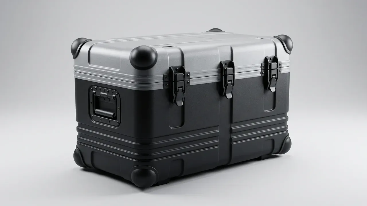
Quick answer: The pressure decay method charges a case to 20 kPa, settles, then times 60 seconds of drop against a 0.5 kPa limit. A reading only counts when the case, the fixture and the sensor are all in order.
Table of contents
- What an air leak test measures
- Setting 20 kPa, 60 seconds and 0.5 kPa
- How much temperature moves the number
- Four places where leaks start
- Passing the decay test is not IP67
- FAQ
1. What an air leak test measures
An air leak test does not ask whether water gets in. It asks how much gas leaves a closed cavity per unit of time: leak rate equals pressure drop times cavity volume, divided by the measuring window. A 30 L case losing 0.5 kPa in 60 seconds passes roughly 250 Pa·L/s, enough to catch a missing gasket or a latch not fully closed.
The method spread through case plants for three reasons: no water contact, tens of seconds per piece, and full inspection instead of sampling.
The method has limits. An air leak test reports an equivalent leak, not a protection grade, and assumes the shell stays rigid. Below 2 mm wall thickness a lid sags under 20 kPa, cavity volume shifts, and the reading shifts with it.
2. Setting 20 kPa, 60 seconds and 0.5 kPa
Twenty kilopascals is not arbitrary. Lower and the signal drowns in noise; higher and a thin shell balloons, the lid sinks 1–2 mm, the gasket is pushed aside and a false leak appears. 20 kPa is about 2 m of water column, twice the head in IPX7.
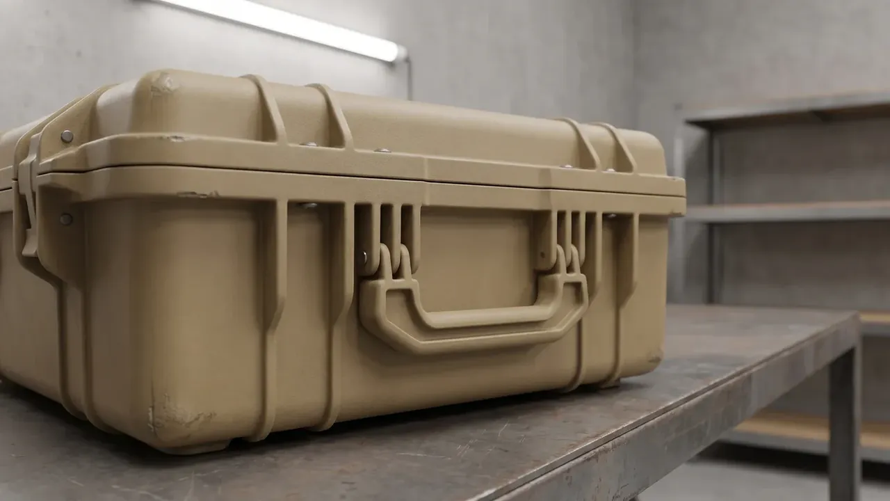
The 60 seconds is best split in two. Gas heats as it is compressed, so an air leak test that times from the moment of charge reads a falsely high start pressure; settle 20 seconds, then count 60.
The 0.5 kPa line comes from volume. For one leak rate a larger cavity loses less pressure: 30 L dropping 0.5 kPa is about 250 Pa·L/s, while a 5 L case at the same figure holds one sixth of that leak, so small cases are often held to 0.1 kPa.
Sensor choice fails more often than the parameters do. A 0–35 kPa range at ±0.2% full scale with 1 Pa resolution is enough; below 1 Pa, a 0.5 kPa limit spans five counts and quantisation eats half the margin.
| Parameter | Setting | Note |
|---|---|---|
| Charge pressure | 20 kPa | about 2 m of water |
| Settle time | 20 s | gas matches wall |
| Measuring window | 60 s | counted after settle |
| Decay limit | 0.5 kPa | 30 L cavity |
| Sensor resolution | 1 Pa | 0–35 kPa range |
3. How much temperature moves the number
Gas pressure follows temperature at roughly 0.34% per °C. At a 20 kPa charge one degree is 68 Pa, which sounds small until the budget is 500 Pa: a 3 °C difference takes 41% of it.
| Difference | Drift at 20 kPa | Share of 0.5 kPa |
|---|---|---|
| 1 °C | 68 Pa | 14% |
| 3 °C | about 0.20 kPa | 41% |
| 5 °C | about 0.34 kPa | 68% |
That is why an air leak test calls for two hours of soak. A case straight off the moulding machine can run 8–10 °C above shop temperature, and on the fixture it reads a large decay and is condemned as leaking.
Three habits keep the error down: dry the air supply to within 2 °C of ambient, keep the bench off windows and outlets, and never hold the case against the body wall, since a 33 °C palm warms a patch fast.
Charging too quickly is the other trap in an air leak test. Filling 30 L to 20 kPa in 0.3 seconds can raise gas temperature past 5 °C, and a 20 second settle may not be enough.
4. Four places where leaks start
Eight out of ten failures in a lot come from four places, always in this order: relief valve, hinge bore, weld line, insert thread.
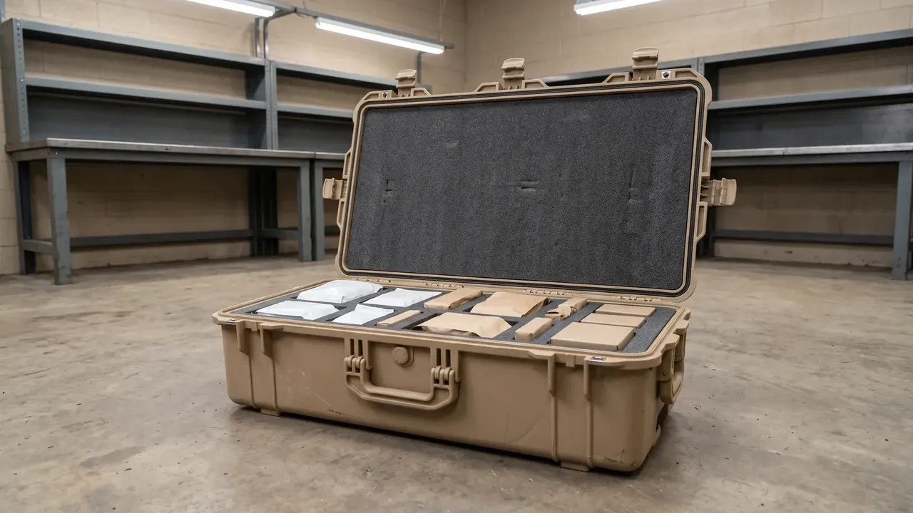
The valve comes first: its sealing face is tiny. One grain of sand 0.5 mm across under the disc sends decay past 100 Pa while the case looks perfect.
The hinge bore comes second: it runs through the wall. Pin clearance is often 0.1–0.2 mm and a single O-ring does the sealing; pinched or missing at assembly, air goes straight through.
The weld line comes third, opposite the gate. Ten degrees low on melt or fifteen on mould temperature leaves a continuous micro-gap where two flow fronts meet, invisible by eye, obvious under pressure.
The insert thread comes fourth: blind-hole floor thickness. Tap 1 mm too deep, leave 0.8 mm of wall, and gas seeps along the thread.
| Location | Cause | Fix |
|---|---|---|
| Relief valve | grit under the disc | blow out, retest |
| Hinge bore | O-ring pinched | new ring, add a stop |
| Weld line | low melt or mould temp | reset process |
| Insert thread | thin blind floor | deepen the floor |
Validate the fixture first: clamp the halves, run 60 seconds dry, keep decay under 0.05 kPa, then feed a 0.5 mL/min calibrated leak and confirm the bench sees it. A spread above 0.1 kPa across three runs of an air leak test points at the bench, not the case.
5. Passing the decay test is not IP67
An air leak test uses gas; a protection grade uses liquid. Neither replaces the other. Surface tension lets a 0.05 mm hole hold back 1 m of water, while the same case shows the leak instantly under pressure.
That sensitivity cuts both ways: the decay method catches micro-leaks long before immersion, and also condemns sound parts, such as a gasket with release agent on its face, where gas travels the interface.
A case that passes IEC 60529 IPX7 at 1 m for 30 minutes usually decays under 0.3 kPa in 60 seconds; a case decaying 0.8 kPa shows droplets on the inner wall within 10 minutes.
The specification carries two lines: a decay limit with its parameters, and an immersion depth with its duration. One line merges two failure modes.
Keep the log wide enough too: date, serial, ambient temperature, set pressure, settle time, start pressure, end pressure, decay, verdict, bench number. Drop the ambient column and nobody can tell, months later, whether a lot drifted because it leaked or because it was cold.
Conclusion
A reading from an air leak test stands only when parameters, temperature, fixture and sensor all agree. Twenty kilopascals and 60 seconds set sensitivity, 0.5 kPa sets the verdict, and one degree of drift consumes a seventh of the budget. Report the decay figure beside an immersion result, and the question of whether a case is sealed gets an answer.
This article discusses only the container (case body) side of specifications and design intent, and does not cover any handling, loading or use of the contents.
Related Reading
- Choosing case seal materials
- Dustproof and waterproof case standards
- IP67 moulded protective case standards
- Waterproof case standards and acceptance
Related Products
- 8 Series — Gun Cases; Military Equipment Cases; Camera Equipment Cases; Drone Cases; Watch Cases; Knife Cases; First Aid Cases; Electronics Equipment Cases
- WL8-2812 PP Gun Case — model WL8-2812
- All protective cases and toolboxes: 7 series, 158 models