

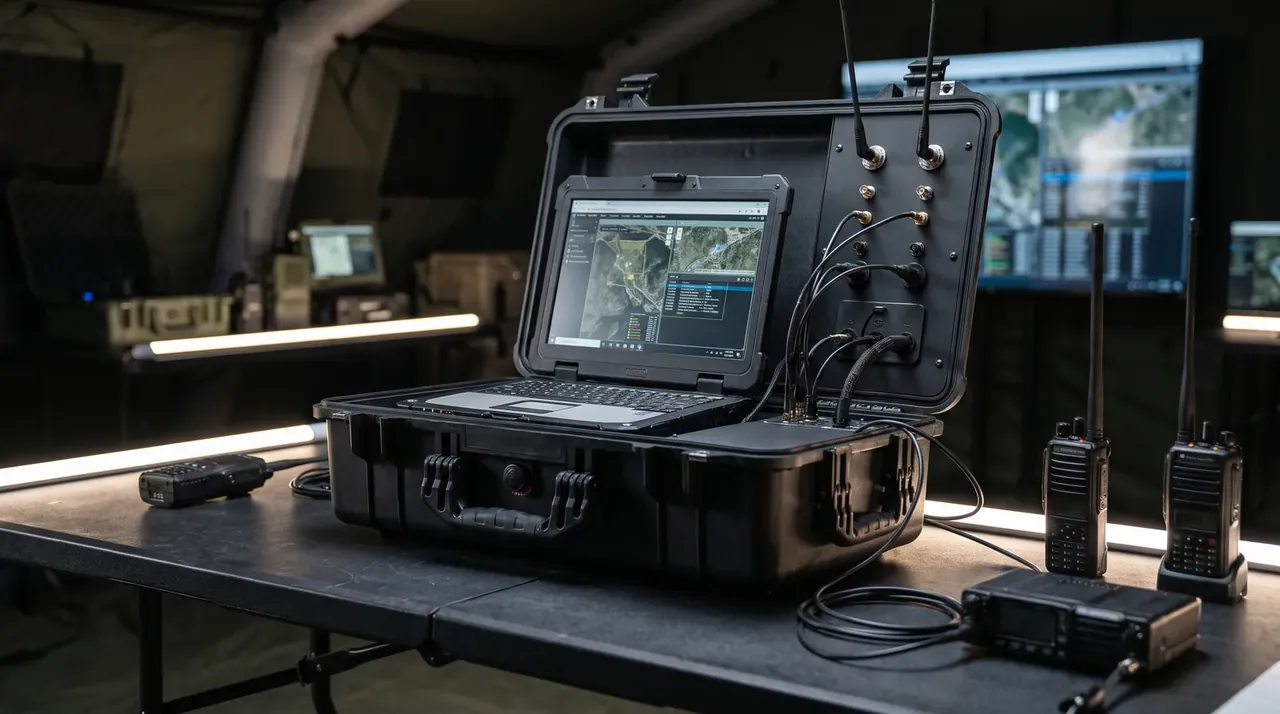
Quick answer: A battery module case does two jobs on the bench: 2 mm barriers between tab centres 18 mm apart, and four 20 mm ports that carry probes outside.
Table of contents
- Why the Tab Barrier Is Fixed at 2 mm
- Where the Four Sensing Ports Land
- An Insulating Liner at 10^12 Ohms, on Purpose
- Cable Ports and the Fifteen-Second Lid Rule
- Keeping the Internal Rise Under 5 K
- FAQ
1. Why the Tab Barrier Is Fixed at 2 mm
A 355 × 150 × 108 mm module sits in the cavity with its tabs standing 12 mm proud of the end face, the two centres 18 mm apart. Across that distance one loose lead falling on the pair is a dead short.
The barrier is 2 mm thick, and three limits squeeze that number. At 1 mm the rib top wanders 0.4 mm after the mould cools and scrapes the tab root on the way in. At 3 mm the rib eats 3 mm of an 18 mm centre distance, leaving a 7.5 mm slot per side for a 30 mm tab that needs room to move, so the module jams halfway down. Two millimetres with 1.5 mm clearance per side lets the tab float without touching.
Height runs 16 mm, four above the tab, with 3 mm of free space to the lid foam that closes as the lid lands. Cut it to 12 mm and the module shifts 2 mm vertically, walking the tab root out from behind the barrier. Past 20 mm the module has to be lifted 8 mm further at changeover, which ends one-handed handling.
| Tab centre distance | Rib thickness | Rib top to tab | Slot per side | Module length served |
|---|---|---|---|---|
| 14 mm | 2 mm | 3 mm | 6 mm | 280–320 mm |
| 18 mm | 2 mm | 4 mm | 8 mm | 330–380 mm |
| 22 mm | 2.5 mm | 5 mm | 9.7 mm | 380–420 mm |
| 26 mm | 3 mm | 6 mm | 11.5 mm | 420–480 mm |
2. Where the Four Sensing Ports Land
Two points sit at the tab roots, one on the top face, one in the centre of the base. The first pair answers whether the joint is heating; the second whether heat is even or piling up in a corner.
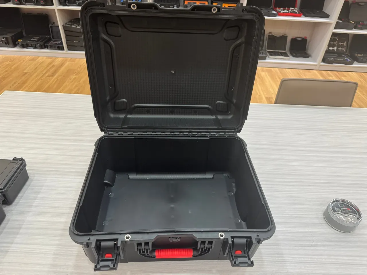
All four ports run through the long side wall at 20 mm, hole centre 8 mm off the tab root. Shrink to 16 mm and the 15 mm grommet has half a millimetre left, rolling its lip after three insertions. Open to 25 mm and the 5 mm annulus becomes a convection path worth 2 K of internal rise.
Position holds within ±3 mm. A probe seated 6 mm deep reads 2 mm off the tab; drift 6 mm and it touches the can, so the two points flatten into one shell reading.
The base point is the one people delete. An 8 mm pocket of still air traps heat, and after 2 h the base runs 4 K above the top face.
| Sensing point | From tab root | Port diameter | Depth | What it reads |
|---|---|---|---|---|
| Positive tab root | 8 mm | 20 mm | 6 mm | Joint heating at the busbar |
| Negative tab root | 8 mm | 20 mm | 6 mm | Symmetry against the positive side |
| Top face, mid-length | 90 mm | 20 mm | 4 mm | Mean can temperature |
| Base centre | 150 mm | 20 mm | 4 mm | Trapped heat under the module |
3. An Insulating Liner at 10^12 Ohms, on Purpose
Most enclosures chase a conductive liner. This one goes the other way, because the bench is already bonded and a second path to earth is a liability. Strapped to a grounded fixture, a dissipative layer would sit in parallel with the tab and push stray current through the sense leads.
The foam is cross-linked polyethylene: 5 × 10^13 Ω surface resistance, 10^14 Ω·cm volume resistivity, 8 mm thick, 45 kg/m³. Fifty insertions leave the cavity below 200 V on a static meter, where plain EVA under the same handling reaches 1.8 kV.
Humidity breaks the figure quietly. At 80% RH an adsorbed film drops it to 8 × 10^11 Ω, still the same order; water uptake under 1% brings it back to 3 × 10^13 Ω after 72 h in a damp chamber.
Conductive foam suits a shipping case and hurts this one.
4. Cable Ports and the Fifteen-Second Lid Rule
Cable ports are drilled apart from sensing ports though both are 20 mm. Six conductors pass: two at 4 mm² for the main loop, four at 0.5 mm² for signals, bundled to 14 mm. A 2 mm silicone grommet leaves a 3 mm annulus.
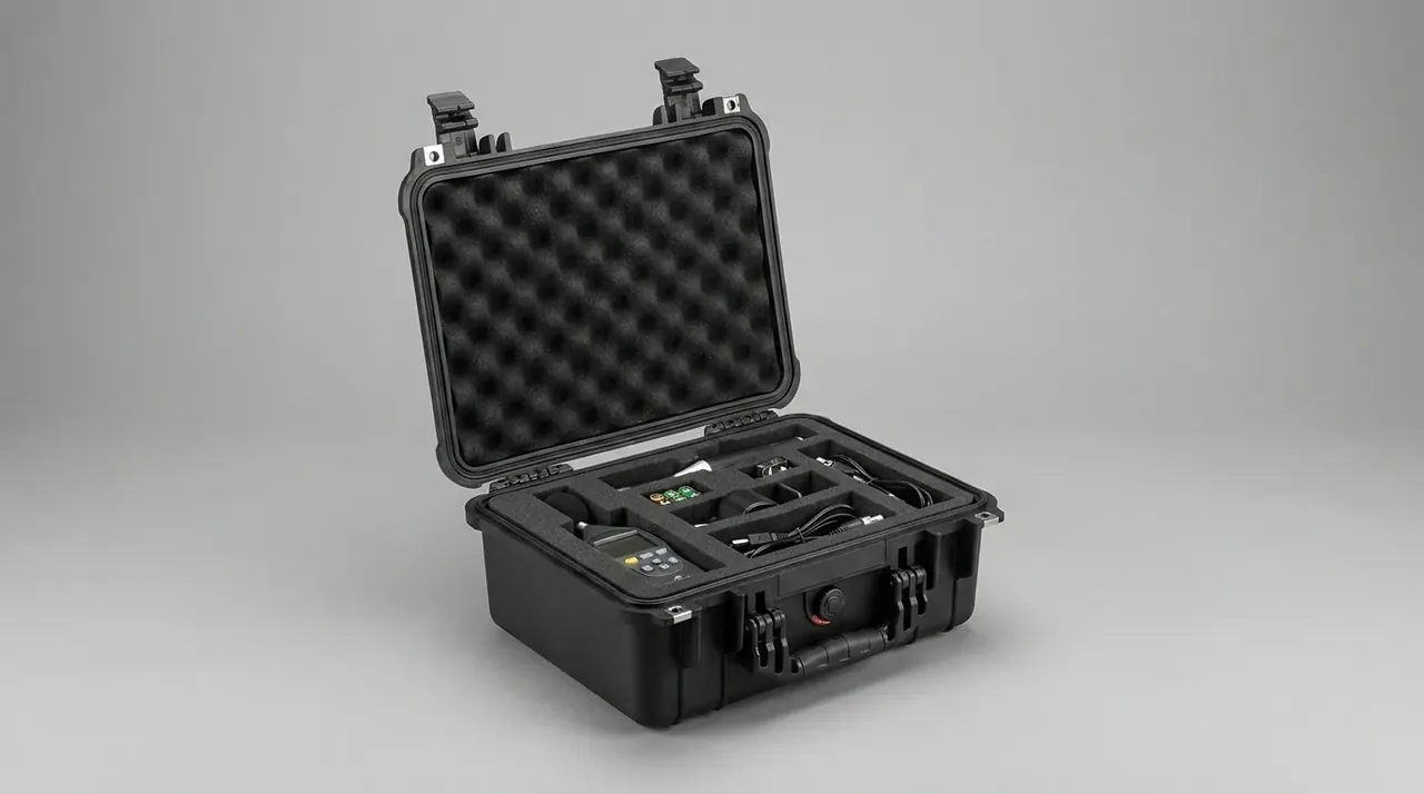
A roller microswitch on the hinge side does the interlocking. At 8° of lid travel the roller releases, the contactor drops out in 0.2 s, and a 100 Ω bleed resistor pulls the loop from 60 V to 5 V in 11 s. That is 14.2 s against a 15 s allowance.
The harness gets a 30 mm service loop each side and a tie-down every 150 mm. After 5000 lid cycles the grommet has stretched under 1 mm and the bundle has moved under 2 mm.
5. Keeping the Internal Rise Under 5 K
The 5 K figure is module surface against ambient: 30 ℃ inside after 2 h in a 25 ℃ room. Three paths share the load.
A 4 mm solid modified-PP wall at 0.22 W/(m·K) runs 3 K above ambient outside and passes heat to the room, about 55% of the load. The 8 mm liner takes about a tenth and saturates after 2 h. The rest leaves through the ports and the 10 mm still-air gap under the lid.
A thicker liner works backwards. The same duty cycle in a 15 mm liner stabilises at 7 K, because the foam keeps heat inside instead of letting the wall do its job.
Conclusion
A battery module case earns its place on the bench with four details: a 2 mm barrier, four 20 mm ports that carry thermocouples outside, a liner above 10^12 Ω, and a lid switch that clears the loop under 15 s. Get all four right and the internal rise settles at 5 K. Anything beyond that belongs to the fixture, not the shell.
Related Reading
- How storage module enclosures are built and tested
- Criteria for choosing a battery safety case
- General design logic for battery enclosures
- Enclosure layout for UPS battery cabinets
Related Products
- 8 Series — Gun Cases; Military Equipment Cases; Camera Equipment Cases; Drone Cases; Watch Cases; Knife Cases; First Aid Cases; Electronics Equipment Cases
- WL8-2812 PP Gun Case — model WL8-2812
- All protective cases and toolboxes: 7 series, 158 models