

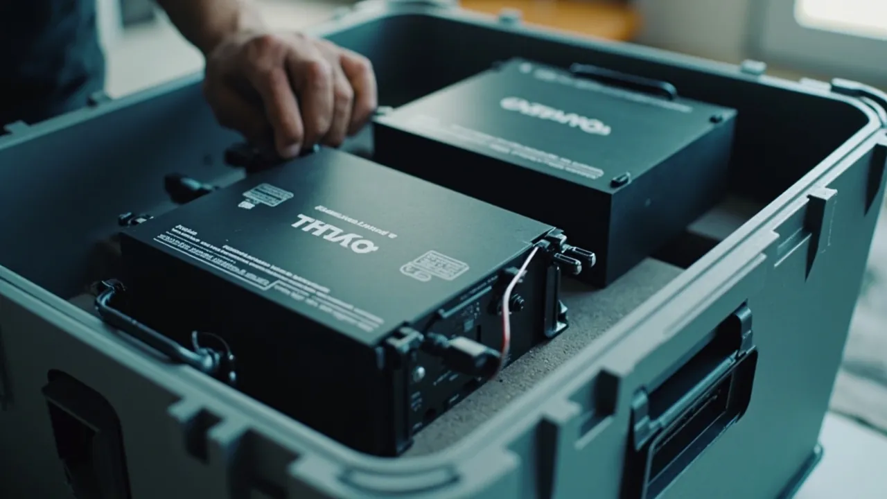
An energy-storage battery module case is fundamentally different from a case for ordinary industrial equipment. It carries mechanical and environmental protection, but it also becomes a link in the dangerous goods compliance chain, and in an extreme event it must buy time for thermal runaway response. The conclusion first: a competent energy-storage module case must satisfy three requirement groups at the same time. The regulatory group covers the eight UN38.3 tests, the UN3480 and UN3481 classifications and marking, the IATA PI965 to PI967 air freight restrictions, and the ADR and IMDG requirements for road and sea. The thermal safety group covers module-level runaway propagation barriers, controlled pressure relief and gas vent paths, and a flame-retardant material system. The mechanical and environmental group covers the sealing grades of IEC 60529 / GB/T 4208, transport testing under ISTA and GB/T 4857, and the necessary static load and stacking capability.
The energy storage industry has shifted in recent years from project-based delivery to volume delivery, and modules and cabinets now move between regions constantly. A 100 kWh class module can weigh several hundred kilograms, so transport must prevent cell deformation, busbar damage and connector damage, while also satisfying increasingly strict compliance review by air and sea carriers.
More critically, lithium batteries carry the irreversible risk of thermal runaway. Once a cell enters thermal runaway through internal short circuit, mechanical damage or external heating, the heat and combustible gas released can propagate through the module. In that situation the case is not a protective box but a risk container. Its job is to limit the energy release envelope, provide a vent path, maintain structural integrity and buy the carrier time for emergency response.
This article is written for structural engineers, EHS and compliance owners, and logistics and purchasing staff at energy storage system integrators. It covers the regulatory map, thermal safety design, mechanical structure, sealing and validation, so that shipping becomes compliant and traceable rather than merely possible.
Note: this article provides engineering and compliance design reference and does not constitute legal advice. Transport modes and routes should follow currently effective regulatory texts, carrier requirements and transport assessment reports issued by qualified testing bodies.
Contents
- 1. The Three Hard Constraints: Regulation, Thermal Safety, Mechanics
- 2. Regulatory Map: UN38.3, UN3480/3481 and IATA PI965-PI967
- 3. How the Eight UN38.3 Tests Shape Case Design
- 4. State of Charge Limits and Pre-Shipment Preparation
- 5. Thermal Runaway Mechanisms and Module-Level Safety
- 6. Runaway Propagation Barriers: Materials and Structure
- 7. Pressure Relief and Gas Vent Path Design
- 8. Mechanical Protection: Module Fixing, Busbars and Connectors
- 9. Electrical Insulation and BMS Static Protection
- 10. Sealing Grades and Condensation: IP65/IP67 and Breather Valves
- 11. Temperature Management: Cold, Heat and Container Environments
- 12. Hazard Labels, Documents and Package Marking
- 13. Transport Validation: UN38.3 T.3/T.4, ISTA and GB/T 4857
- 14. Common Misconceptions and Compliance Recommendations
- Frequently Asked Questions
- Conclusion and Related Reading
1. The Three Hard Constraints: Regulation, Thermal Safety, Mechanics
Constraint one: regulatory compliance. Lithium batteries are dangerous goods. International transport requires type testing under Section 38.3 of the United Nations Manual of Tests and Criteria (commonly called UN38.3) together with a test summary. Sea and road transport must additionally meet the classification, packaging, marking and documentation requirements of the IMDG Code and ADR respectively. Without compliant documentation, no case design, however good, will be accepted onto a vessel, an aircraft or a road vehicle.
Constraint two: thermal safety. Module-level thermal runaway is not simply a single-cell problem. It involves heat generation rate, the heat absorption capacity of adjacent cells, the gas vent path and the structural integrity of the case. The proper role of the case in thermal safety is to limit the propagation envelope and maintain structure, not to extinguish a fire.
Constraint three: mechanical and environmental. Modules are heavy with a high centre of gravity and internal rigid connections such as busbars, bolts and connectors, making them sensitive to shock and vibration. Sea containers can also reach high temperatures and high humidity with condensation, so the case needs appropriate sealing and breathing design.
| Constraint group | Key requirement | Standards and methods | Design implication |
|---|---|---|---|
| --- | --- | --- | --- |
| Regulatory | Type testing, classification, marking, documents | UN38.3, UN3480/3481, IATA PI965-PI967, ADR, IMDG | Structural strength, label layout, document package |
| Thermal safety | Limit propagation, controlled relief | Module propagation testing, UL94 material flammability | Flame-retardant inserts, thermal barriers, vent paths |
| Mechanical and environmental | Shock, vibration and moisture resistance | IEC 60529 / GB/T 4208, ISTA, GB/T 4857 | Sealing structure, locking structure, insert retention |
| Electrical | Insulation and static control | ESD control requirements, insulation resistance requirements | Insulating barriers, grounding and bonding design |
2. Regulatory Map: UN38.3, UN3480/3481 and IATA PI965-PI967
What UN38.3 covers. UN38.3 is the type testing requirement for lithium battery transport, verifying that cells and batteries, including modules, are safe under transport conditions. It does not address the packaging container itself, but the container must not cause additional damage to the battery under those test conditions, and the battery must not disassemble or ignite after testing. Case design must therefore be built around the mechanical and temperature conditions of T.2 through T.5.
UN number classifications.
- UN3480: lithium ion batteries transported alone, without equipment.
- UN3481: lithium ion batteries contained in equipment, or packed with equipment.
- UN3090 / UN3091: lithium metal batteries, alone or contained in or packed with equipment.
Energy storage modules are commonly handled as UN3480 when shipped as standalone cargo. If they are packed together with PCS or BMS control cabinets as part of an equipment assembly, UN3481 may apply. The classification directly determines packing level, marking and documentation, so it must be confirmed at the start of a project.
Air freight restrictions: IATA PI965 to PI967. The International Air Transport Association dangerous goods regulations use packing instructions to distinguish cases: PI965 covers lithium ion batteries shipped alone under UN3480, PI966 covers batteries packed with equipment, and PI967 covers batteries contained in equipment.
State of charge limits. Air freight rules impose state of charge limits on lithium ion batteries shipped alone under UN3480, commonly requiring no more than 30 percent of rated capacity. That figure is adjusted through rule revisions and the currently effective text should always be consulted. Some sea and road regulatory systems apply similar or related limits. A SoC limit means discharge preparation before packing is a necessary compliance step, not an optional one.
Road and sea. European road transport is governed by ADR and sea transport by the IMDG Code. For general requirements on dangerous goods transport and case compliance, see dangerous goods transport and case compliance.
| Transport scenario | Common UN number | Main rules | Key limits |
|---|---|---|---|
| --- | --- | --- | --- |
| Module alone by air | UN3480 | IATA PI965 | SoC commonly capped at 30 percent, strict packing level |
| Module with equipment by air | UN3481 | IATA PI966 / PI967 | Graded by packing form, different marking |
| Module by sea | UN3480 / UN3481 | IMDG Code | Segregation, marking and documentation |
| Module by road | UN3480 / UN3481 | ADR or equivalent national rules | Vehicle, marking and accompanying documents |
| Lithium metal batteries | UN3090 / UN3091 | IATA PI968 to PI970 | Different rules from lithium ion, confirm separately |
3. How the Eight UN38.3 Tests Shape Case Design
UN38.3 contains eight tests, and each implies requirements for the packaging design.
| Test | Name | Condition direction | Implied case design requirement |
|---|---|---|---|
| --- | --- | --- | --- |
| T.1 | Altitude simulation | Low pressure environment | Sealed case needs pressure equalization capability |
| T.2 | Thermal test | High and low temperature cycling | Insert materials must resist temperature without embrittling or softening |
| T.3 | Vibration | Defined frequency range and duration | Fastening and support must resist fatigue loosening |
| T.4 | Shock | Defined acceleration and pulse width | Cushioning insert must absorb shock and limit displacement |
| T.5 | External short circuit | External short circuit condition | Electrical isolation between terminals and conductors |
| T.6 | Impact and crush | Mechanical load | Case must resist crushing, module must resist deformation |
| T.7 | Overcharge | Electrical condition | BMS related, indirectly related to packaging |
| T.8 | Forced discharge | Electrical condition | Indirectly related to packaging |
Why T.1 matters. The test is conducted under low pressure to verify cell and battery tolerance. The direct implication for packaging is that a sealed case unable to balance internal and external pressure can suffer gasket eversion, case bulging or difficulty opening during high-altitude or plateau transport. The solution is a controlled pressure relief structure; see case pressure equalization valve.
Why T.2 matters. Temperature cycling tests the thermal stability of insert materials. Ordinary PE foam softens at high temperature and embrittles at low temperature, and either behaviour can cause support failure. Insert materials should retain shape and elasticity across the transport and storage temperature range. For related design thinking, see extreme temperature case design.
Why T.3 and T.4 matter. Vibration and shock are the most sustained and most universal loads in transport. Module fixing must resist both loosening from sustained vibration and displacement from instantaneous shock. The former requires anti-loosening features such as thread locking, locating shoulders and elastic preload; the latter requires the absorbing and recovering capability of the cushioning insert.
Why T.5 and T.6 matter. External short circuit and impact crush point to electrical isolation and structural strength. Terminals, busbars and metal case components must maintain reliable insulation distances so that displacement or condensation during transport cannot cause creepage or short circuit.
4. State of Charge Limits and Pre-Shipment Preparation
The engineering meaning of a SoC limit. The lower the state of charge, the less electrochemical energy is stored inside the cell, and the less energy is released during an internal short circuit. Transport rules therefore generally require a reduced SoC. From an engineering standpoint, reducing SoC reduces the risk source, while the case limits the consequences. The two are complementary, not interchangeable.
A standard pre-shipment preparation sequence.
- Confirm the type test status of the cells and module, checking that the UN38.3 test summary covers the model and batch.
- Adjust SoC to the required range per the applicable rules, and record the adjusted value and the test time.
- Perform visual and insulation inspection, confirming no swelling, no electrolyte leakage, no terminal damage and acceptable insulation resistance.
- Confirm the BMS is in a safe state, for example transport mode or low-power mode activated.
- Complete packing and fixing, confirming the module has no free space to move inside the case.
- Complete marking and documentation, including hazard labels, UN number, package marks and transport documents.
- Record and retain the packing inspection record, SoC record and packing photographs.
Additional considerations for sea freight. Sea transport involves long duration, large temperature swings and high humidity inside the container. Beyond SoC control, internal humidity management and condensation risk need attention. Condensation reduces insulation and corrodes metal parts. For related sealing and breathing design, see waterproof case IP ratings explained.
5. Thermal Runaway Mechanisms and Module-Level Safety
The basic chain. Lithium battery thermal runaway typically passes through three stages. First, internal heat generation begins through internal short circuit, mechanical damage, overcharge or external heating, and temperature rises. Second, once temperature passes a threshold, the separator fails and the cathode and anode materials begin exothermic reactions, so the heat generation rate rises sharply. Third, at higher temperature the electrolyte decomposes and generates large volumes of combustible gas, internal pressure rises until the vent opens, and hot gas and particles are ejected.
Three critical points at module level.
Point one: the energy release of a single cell cannot be prevented, only its sphere of influence limited. The core objective of module-level design is therefore runaway propagation resistance, preventing adjacent cells from entering runaway sequentially due to heat exposure.
Point two: gas venting must be addressed. The gas produced by thermal runaway is combustible and hot. If the case is fully sealed with no vent design, gas cannot escape, internal pressure rises, and the case structure can fail, potentially ejecting fragments. Complete sealing is therefore not always an advantage in an energy-storage module case.
Point three: structural integrity determines emergency response time. The ability of the case to maintain structural integrity under high temperature and shock directly affects the response time available to carriers and fire services.
Summary of design principles. The reasonable role of the case in thermal safety is to limit the propagation envelope, provide directional venting, maintain structural integrity and buy time for emergency response. Any claim of preventing ignition or fully blocking thermal runaway lacks an engineering basis.
6. Runaway Propagation Barriers: Materials and Structure
Three dimensions of material selection.
Dimension one: flammability rating. Insert and structural materials should meet the applicable flammability requirement. UL94 V-0 is a commonly referenced grade in electronics and new energy applications, meaning the specimen self-extinguishes within 10 seconds after flame removal in the vertical burning test with no dripping that ignites cotton. Quote the specimen thickness and orientation alongside the grade.
Dimension two: temperature capability. Materials must maintain shape and support function under expected thermal exposure. Temperature capability varies widely between material systems and should be selected against the thermal behaviour of the module.
Dimension three: thermal insulation capability. Insulating materials with low thermal conductivity slow heat transfer to adjacent cells. Common approaches include thermal barrier layers between module positions and insulating panels on the inner walls of the case.
Three structural barrier strategies.
- Zoned isolation: divide modules into separate cavities with solid thermal barrier walls between them to limit the propagation path.
- Directional heat routing: design a directional exhaust channel at the top or end of the case to lead hot gas away from personnel and combustible materials.
- Pressure management: allow internal pressure to release in a controlled way through a relief structure, avoiding shell failure.
| Material or structure | Primary function | Advantages | Limitations |
|---|---|---|---|
| --- | --- | --- | --- |
| Flame-retardant EVA or EPDM insert | Cushioning, flame retardancy, locating | Combines cushioning with flame retardancy, good formability | Performance decays under long-term high temperature |
| Metal inner frame | Structural strength and heat conduction | High rigidity, heat resistant | Adds weight, requires insulation treatment |
| Thermal barrier divider | Slows heat transfer | Acts directly on the propagation path | Adds volume and weight |
| Flame-retardant coating or wrap | Surface flame retardancy | Lower cost | Limited scratch resistance |
| Steel outer case | Structural integrity and crush resistance | High strength, recyclable | Heavy, requires corrosion protection |
7. Pressure Relief and Gas Vent Path Design
Why relief is needed. The T.1 altitude simulation test already demonstrates the existence of pressure differentials. Under thermal runaway, internal pressure rises far faster than in normal transport conditions. The purpose of relief design is to give pressure a controlled exit rather than letting it destroy the case.
Three ways to implement relief.
Option one: one-way relief valve. Releases when internal pressure exceeds a set threshold while preventing external water and dust from entering. Suited to applications that must maintain a relatively high sealing grade.
Option two: breathable membrane or waterproof vent. Uses a hydrophobic membrane to provide continuous slow pressure equalization while maintaining the IP rating. Suited to normal transport pressure management.
Option three: directional relief channel. A structurally weaker or openable area is designed at a specific location so that gas vents in a chosen direction during runaway. This requires coordination with the carrier and clear indication of the vent direction on the label.
Vent path design points.
- The vent direction should avoid the personnel handling face and adjacent combustible materials.
- The vent path must not be blocked by inserts or fixing components.
- No easily melted or flammable accessories should be located near the vent opening.
- For multi-cavity cases, evaluate air communication between cavities so that cross-flow does not enlarge the affected area.
An important compliance boundary. Relief design must not weaken the basic strength requirements of dangerous goods packaging. Any change involving packaging structure should be re-evaluated against the applicable packing level and test requirements.
8. Mechanical Protection: Module Fixing, Busbars and Connectors
Three levels of module fixing.
Level one: in-case locating. Molded inserts or locating blocks limit horizontal movement of the module. The purpose of locating is not clamping but limiting the maximum displacement. Over-tight clamping creates sustained stress under vibration.
Level two: vertical restraint. Bottom support and top retention limit vertical movement. Modules are heavy, so vertical acceleration is the dominant load source.
Level three: anti-loosening fastening. Bolted connections should use anti-loosening measures, and torque should be confirmed during the packing inspection.
Busbar and connector protection. A busbar is a rigid conductor, and relative displacement during transport bends it, potentially cracking the connection point. Connectors can loosen or deform their terminals under vibration. Protection points are: busbars need independent support, connectors need protective caps, and harnesses need fixing points and must not be left under tension.
Specific insert design requirements. Custom insert cavities should conform to the module outline so that no displacement occurs in transit. The insert base should include a cushioning layer to absorb vertical shock, and top retention should apply light preload without over-compression. For design methods, see custom foam insert design guide and cushion liner design and shock absorption.
9. Electrical Insulation and BMS Static Protection
The goal of insulation design. Battery systems can operate at several hundred volts or more, and insulation failure during transport creates short circuit and electric shock risk. Insulation design must address solid insulation such as barriers and brackets, creepage distance and clearance together, with margin for possible condensation and contamination.
Critical insulation locations.
- Between the module and metal case components: use insulating barriers or insulating coatings.
- Between terminals and adjacent conductors: maintain the specified creepage distance and clearance.
- Where busbars pass through: use insulating sleeves or isolating structures.
- Where harnesses contact metal edges: add sleeving to prevent insulation abrasion over time.
BMS static protection. A BMS control board contains an MCU, sampling chips and communication interfaces, all of which are static-sensitive. During transport and handling, avoid touching interfaces directly after triboelectric charging. See ESD shield case design.
Practical insulation checking. Measure insulation resistance before packing and record it. For high-voltage modules, use the specified test voltage. Record the ambient temperature and humidity alongside the reading, because insulation resistance is strongly humidity dependent. Insulation data without recorded ambient conditions has limited comparability.
10. Sealing Grades and Condensation: IP65/IP67 and Breather Valves
IEC 60529, and the equivalent GB/T 4208, uses two digits to define enclosure protection. The first digit covers solid ingress including dust, the second covers water.
| IP rating | Dust | Water | Positioning for module transport |
|---|---|---|---|
| --- | --- | --- | --- |
| IP54 | Limited dust protection | Splash resistant | Short in-plant transfer with covered handling |
| IP65 | Dust tight | Jet-water resistant | Road transport, ordinary warehousing |
| IP67 | Dust tight | Short-term immersion | Sea freight, intermodal, rainy season |
| IP68 | Dust tight | Continuous immersion | Special cases, usually unnecessary |
Why condensation is a special concern. An energy-storage module case contains metal conductors and insulating components, and condensation reduces insulation and corrodes metal. Condensation occurs when internal humidity is relatively high and the temperature falls below the dew point. In a highly sealed case, humidity management therefore cannot rely on sealing alone; it also requires desiccant and controlled breathing.
Balancing sealing and breathing.
- A fully sealed case develops large pressure differentials during temperature cycling, which can damage seals.
- A fully open case cannot exclude water and dust.
- The sensible approach is sealing plus controlled breathing: the case is sealed overall, with a hydrophobic breathable vent providing pressure equalization while blocking liquid water.
For sealing material and structure options, see case seal materials and structure and IP67 protective case design and validation.
11. Temperature Management: Cold, Heat and Container Environments
The effect of high temperature. Container interiors can reach significantly higher temperatures than ambient under direct sunlight. High temperature accelerates material aging, speeds electrolyte side reactions and affects the dimensional stability of insert materials. The material system should retain function across the expected high temperature range.
The effect of low temperature. Low temperature reduces the elasticity of insert materials and therefore their cushioning capability. Battery capacity and charge-discharge capability also fall at low temperature, but that is a system behaviour rather than a packaging issue. The packaging concern is that the insert does not embrittle or powder at low temperature.
The effect of thermal shock. Moving from cold storage to warm transport creates thermal shock, producing internal material stress and condensation. Thermal shock affects sealing structures most noticeably, because different materials have different coefficients of thermal expansion.
Measures that can be taken.
- Select a wide-temperature material system and state the temperature range in the technical agreement.
- Where necessary, add an insulating panel to the inner wall to slow heat transfer.
- Fit desiccant and humidity indication to control condensation risk.
- For transport on extreme climate routes, consider recording internal temperature and humidity data for traceability.
For related design thinking, see extreme temperature case design.
12. Hazard Labels, Documents and Package Marking
Marking is the physical evidence of compliance. Carriers look at marking first when accepting cargo, and non-conforming marking leads to immediate rejection.
Common marking elements.
- Class 9 dangerous goods label (lithium battery label): applied as required, with compliant size and position.
- UN number: UN3480, UN3481 and so on.
- Package marks: applied according to the applicable packing level.
- Orientation marks: arrows pointing up and similar.
- Emergency contact information: provided as required by the applicable rules.
- Overpack marks: applied when a pallet or outer box is used.
Supporting documents.
- UN38.3 test summary.
- Transport condition assessment or transport test report, per carrier and regulatory requirements.
- Dangerous goods declaration documents, per transport mode.
- Packing inspection and SoC records.
- Material safety data sheets as applicable.
Practical advice on label layout. Reserve a flat surface for the label area during case design. Avoid applying labels over curved surfaces or reinforcing ribs, where edges lift and peel. For reusable cases, use durable labels or provide a dedicated label recess. Marking is not a late-stage add-on; it should be planned alongside the structural design of the case.
13. Transport Validation: UN38.3 T.3/T.4, ISTA and GB/T 4857
A three-layer validation logic.
Layer one: cell and battery type testing. Covered by UN38.3, verifying that the cells and battery themselves are safe under transport conditions. This is a mandatory compliance requirement.
Layer two: packaging performance testing. Conduct the applicable tests for the intended packing level. For non-dangerous-goods scenarios or as supplementary validation, ISTA procedures or the GB/T 4857 series can be used.
Layer three: system-level transport simulation. Load actual modules into the actual case and run drop, vibration, stacking and temperature-humidity cycling validation for the real distribution environment, then check internal displacement, insulation resistance and insert condition.
Example quantified acceptance criteria for validation.
| Validation item | Example criterion | What to record |
|---|---|---|
| --- | --- | --- |
| Vibration | Fasteners not loosened, insert not displaced, insulation resistance acceptable | Frequency range, duration, axis |
| Shock or drop | No case rupture, no seal failure, no visible module deformation | Height or acceleration, orientation, cycles |
| Stacking | No permanent deformation, no cavity collapse | Load, duration, ambient temperature and humidity |
| Temperature and humidity cycling | No condensation pooling, no material embrittlement or softening | Temperature range, cycle count, humidity |
| Pressure change | No gasket eversion, case opens normally | Pressure differential range, duration |
On the boundaries of standards citation. Certain environmental test methods, such as the temperature, humidity, vibration and shock methods in MIL-STD-810H, can be used as methodology reference, but note that this standard is a test methods standard and not a military certification. When citing it in a commercial context, describe it as testing conducted according to the corresponding methods. See MIL-STD-810H environmental testing and case compliance, transport packaging test procedures and ISTA, GB/T 4857 transport packaging testing and ASTM D4169 distribution cycle testing.
On validating shock-resistant structures. The energy absorption and recovery capability of the cushioning structure is central to shock testing; see sealing and shock-resistant structure design.
14. Common Misconceptions and Compliance Recommendations
Misconception one: treating a storage module like ordinary equipment. Ignoring UN38.3, UN numbers, hazard labels and documentation means the cargo gets rejected at the port or airport.
Misconception two: assuming a more sealed case is always safer. A fully sealed case with no relief design carries risk both under pressure differentials and under thermal runaway. Sealing and controlled breathing must be balanced.
Misconception three: setting no ignition as a packaging design goal. Packaging cannot prevent single-cell thermal runaway; it can only limit propagation and consequences. Such wording should not appear in marketing or documents.
Misconception four: SoC is unrelated to safety. SoC directly determines the energy a cell can release and is a key risk-source control parameter.
Misconception five: measuring insulation resistance without recording ambient conditions. Humidity strongly affects insulation resistance, and records without ambient conditions cannot be compared or traced.
Misconception six: skipping insert-to-module fit validation. A compliant insert drawing does not mean the physical fit is correct. Physical trial fitting and transport validation are compulsory.
Compliance and engineering recommendation checklist:
- Confirm the transport scenarios (air, sea, road) and the applicable UN number at project start, and lock the packing level requirements.
- Verify that the UN38.3 test summary covers the model and batch.
- Adjust SoC as required and retain records.
- Design controlled relief and directional vent paths, and assess their impact on packaging strength requirements.
- Use flame-retardant, temperature-resistant materials for inserts and structural parts, with the temperature range and flammability grade stated in the technical agreement.
- Design the insulation scheme for high-voltage modules, specifying creepage distance and clearance requirements.
- Fit desiccant and humidity indication to control condensation risk.
- Reserve the label area during the structural design stage.
- Complete three-layer validation (battery type testing, packaging performance testing, system-level transport simulation) and retain quantified records.
- Maintain communication with qualified testing bodies and carriers so that documentation and marking remain current.
On supplier selection. An energy-storage module case requires coordination across structure, materials, sealing, thermal safety and compliance documentation, so the supplier should be able to support insert drawing review, physical trial fitting, and sealing and transport test coordination. In the protective case sector, JUNZHJIA provides end-to-end support from case structure design and molded insert customization through sealing and transport validation. Its manufacturing system under Kexin New Materials (Guangdong) Co., Ltd. can develop molded inserts by module outline and weight, configure flame-retardant and insulating material options, and cooperate on trial fitting and validation records. For selection methodology, see instrument case selection guide and how to choose a case OEM factory.
Frequently Asked Questions
Q: Does an energy storage module case require UN38.3 certification? A: The subject of the requirement needs to be distinguished. UN38.3 is a type testing requirement for cells and batteries, including modules, verifying the safety of the battery itself under transport conditions rather than certifying the packaging container. What the case must do is ensure that under the UN38.3 test conditions, particularly altitude simulation, thermal, vibration and shock, it does not cause additional damage to the battery, and that it meets the performance requirements of the applicable packing level. In practice, projects therefore run two tracks in parallel: the battery side completes UN38.3 testing and obtains a test summary, while the packaging side completes performance testing for the applicable packing level and issues records. If a customer or carrier asks for packaging certification, confirm which standard and which packing level they mean, so that document gaps are not created by conceptual confusion.
Q: Is a higher sealing grade always better? A: No. In energy storage applications a balance is required. High sealing blocks water and dust, but it also creates larger pressure differentials during temperature and altitude changes, which can damage seals and make the case difficult to open. Under thermal runaway, a fully sealed case without a relief path also faces structural failure risk from rapidly rising internal pressure. The sensible approach is overall sealing plus controlled breathing: the case maintains IP65 or IP67 capability while a hydrophobic breathable vent provides pressure equalization, with a directional relief channel added where necessary. The key is to include the relief structure in the overall strength assessment, and to reconfirm that any structural change still meets the applicable packaging requirements and test conditions.
Q: Do state of charge limits affect case design? A: Indirectly. The SoC limit is a risk-source control measure that reduces the electrochemical energy stored in a cell and therefore the energy released during an internal short circuit. Its indirect effect on case design is that a lower SoC does not change module weight, dimensions or centre of gravity, so mechanical fixing and cushioning requirements are unchanged. In some projects, however, customers may require integrated SoC monitoring or logging devices inside the case, which affects internal layout and harness routing. SoC adjustment must also be completed before packing, which means the packing workflow should include a SoC confirmation step with retained records. It is advisable to combine the SoC record, insulation check record and packing inspection record into a single packing checklist to form a complete traceable chain.
Q: If thermal runaway occurs during transport, what can the case actually do? A: It should be positioned objectively. A case cannot prevent single-cell thermal runaway nor extinguish the reaction. Its function is to limit consequences. First, thermal barrier dividers and zoned structure slow heat transfer to adjacent cells and adjacent cavities, reducing propagation probability. Second, directional relief and exhaust channels lead hot gas away from personnel and combustible materials, preventing the case from failing as a whole and ejecting fragments due to rising internal pressure. Third, flame-retardant materials and structural integrity design buy response time for carriers and emergency responders. For external communication, avoid absolute claims such as fireproof or fire-preventing case body, and use verifiable wording such as limiting the thermal propagation envelope and maintaining structural integrity.
Q: How should insert materials be selected? Can ordinary PE foam be used? A: Caution is needed. Ordinary PE foam is inexpensive and cushions reasonably, but it has two problems. First, its temperature capability is limited: it softens at high temperature and embrittles at low temperature, so it may lose support capability after temperature cycling. Second, it generally has no flame retardancy, so under thermal exposure it can become a fuel source and release smoke. Energy storage applications tend to use material systems with flame retardancy and temperature resistance, such as flame-retardant EVA, flame-retardant EPDM, or combinations with other structural components. Selection should confirm the flammability grade together with specimen thickness and orientation, the permitted temperature range, compression set behaviour, and performance decay over long-term use. Final judgement should rest on physical trial fitting and transport validation results, because a compliant drawing does not mean a usable part.
Q: What additional points apply to sea freight export of energy storage modules beyond UN38.3? A: Sea freight adds concerns in both environmental and documentary areas. On the environmental side, duration is long, temperature cycling is large and container humidity is high, so sealing grade, desiccant quantity and condensation risk need attention, metal parts should have corrosion protection, and pressure changes may stress seals so a breather vent is advisable. On the documentary side, classification, packing level, marking and declaration must be confirmed under the IMDG Code, and overpacks must be marked per the rules. Loading position, segregation requirements and emergency contact information may also be checked by the carrier. Confirm the specific marking and document checklist with the carrier before booking, so the shipment is not rejected on arrival.
Q: What insulation performance should the case achieve? A: It depends on the module voltage class and the applicable requirements; there is no universal figure. In practice, determine the required creepage distance and clearance from the system maximum voltage, referencing the relevant system standards and customer specifications. Install insulating barriers or sleeves between the module and metal case components, between terminals and adjacent conductors, and where busbars pass through. Add sleeving where harnesses contact metal edges to prevent insulation abrasion. Measure and record insulation resistance before packing, and record ambient temperature and humidity as well, because humidity strongly affects readings. Condensation must also be considered: even if initial insulation is acceptable, condensation during transport can reduce insulation performance, which makes humidity management part of insulation design.
Q: How can a case design be proven to actually work? A: Use three layers of validation. Layer one is battery-level type testing, covered by UN38.3 with a test summary obtained. Layer two is packaging container performance testing for the applicable packing level. Layer three is system-level transport simulation: load actual modules into the actual case and run vibration, shock or drop, stacking and temperature-humidity cycling for the real distribution environment, then open the case and check internal displacement, fastening condition, insert deformation and insulation resistance. The value of layer three is exposing the gap between a compliant drawing and a physical mismatch. Whichever layer is performed, quantified criteria must be defined before execution, for example no loosened fasteners, no insert displacement and insulation resistance not below a stated value. A pass conclusion without quantified criteria has little engineering meaning.
Q: How should the return on investment for this case solution be assessed? A: Assess it as avoided rejection and incident cost. The main benefit items are avoiding port rejection and demurrage charges caused by marking or documentation non-conformity, avoiding module rework or scrap caused by case damage, reducing incoming inspection failures from insulation or condensation problems, lowering handling labour, and being better able to provide compliance evidence during customer audits and insurance processes. Cost items include case and insert purchase, maintenance and replacement, packing labour and document management. In energy storage projects, the cost of a single rejection or a single scrapped module usually far exceeds the entire packaging investment, so assessment should be based on risk exposure rather than simple price comparison. Reusable circulation solutions also generally outperform single-use wooden crates across multiple deliveries.
Conclusion and Related Reading
An energy storage module transport case is a cross-disciplinary engineering item. It is simultaneously a component of the dangerous goods compliance chain, the last physical barrier for thermal safety, and the mechanical protection carrier for heavy precision equipment. Its correct design goal is not to completely prevent risk but to ship compliantly, limit the consequence envelope, maintain structural integrity and leave a traceable record. The path can be summarized in four steps: first lock the transport scenario and applicable regulations and confirm the UN number and packing level; then design sealing, cushioning, insulation and fixing around the UN38.3 test conditions; then address thermal safety with flame retardancy, thermal barriers and controlled relief; and finally confirm through three-layer validation with quantified criteria.
On the supply side, a manufacturer able to support structural design, insert customization, sealing solutions and transport validation coordination substantially reduces project iterations and documentation risk for energy storage projects. In protective case customization, JUNZHJIA supports developing molded inserts by module outline and weight, configuring flame-retardant and insulating materials, cooperating on breather and relief structure design, and supporting trial fitting and validation records. This makes it suitable for energy storage system integrators that need stable long-term supply and OEM/ODM cooperation.
Related Reading