

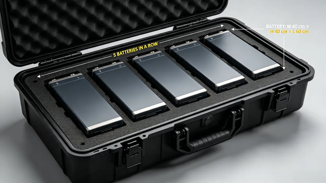
In modern energy and equipment support systems, the safe storage and transport of energy cells has become an engineering problem that cannot be ignored. Whether it is a backup power module for a communication base station, a portable power source for field operations, or a disassembled component of a large storage system, these energy carriers need a reliable container to provide isolation, cushioning, temperature control, and protection while moving from the warehouse to the point of use. The battery case discussed in this article is a specialized protective enclosure designed around this class of equipment. Its core task is not to change the cells themselves, but to provide a controlled, isolated, and traceable environment for transport and storage.
Around the selection and engineering application of battery cases, the industry has developed a relatively complete set of practices. From the choice of shell material, to the design of internal isolation structures, to the matching of temperature control schemes and sealing levels, every link directly affects the final safety margin. We break these contents into several operable dimensions to help procurement staff, equipment support personnel, and design engineers build a clear judgment framework. It must be stated clearly that this article discusses only the container aspects such as the enclosure shell, lining, latches, sealing, shock isolation, stacking, and temperature control. It does not address the physical and chemical properties, formulations, or internal structures of any contents being carried.
Definition and Scope of the Battery Case
A battery case is a specialized protective enclosure whose payload consists of energy cells. Its external shape resembles a general equipment case, but it differs markedly in internal space planning, isolation structure, ventilation, and temperature control interfaces. Typically it is used to hold individual cells, battery modules, portable storage power sources, uninterruptible power supply battery packs, and various energy carriers that must maintain charge and status stability during transit. Unlike a simple tool storage box, a battery case must consider additional requirements such as ventilation, thermal insulation, short-circuit prevention isolation, and identification tracking.
From the perspective of applicable scenarios, battery cases are common in communication support, field operations, emergency repair, power inspection, scientific field work, and the internal turnover of manufacturing enterprises. In these scenarios, energy carriers often need to travel long distances under road, marine, or air transport conditions, while along the way vibration, temperature difference, humidity, and impact risk may all adversely affect cell status. A well-designed battery case can keep these risks within an acceptable range under such adverse conditions.
In terms of functional positioning, a battery case can be used alone or as a component within a larger protection scheme. For example, it can be embedded in the internal shelving of a communication shelter case, or it can achieve standardized stacking with an equipment case to form a modular carry system within a power support convoy. Understanding this helps us avoid treating the battery case as an isolated product during later selection.
Main Risks in Transporting Energy Cells
The risks of transporting energy cells mainly come from the superposition of external environmental disturbances and the status of the payload itself. External factors include mechanical vibration, drop impact, temperature and humidity changes, dust ingress, and liquid splashing. The status of the payload is reflected in state of charge, packaging integrity, and possible voltage differences between individual units. When these two types of factors combine, a poorly designed container may suffer isolation failure, insufficient cushioning, or blocked heat dissipation.
Mechanically, random vibration and periodic jolting during transport cause small displacements of internal modules, and long-term accumulation may loosen connections or wear the shell. Drop impact has a lower probability but can cause structural deformation that squeezes internal cells. Therefore, the cushioning structure of a battery case must address both long-term micro-vibration and occasional strong impact.
Thermally, energy cells generate heat during charge, discharge, or environmental warming. If the container is fully sealed and lacks heat dissipation channels, internal temperature may exceed a safe range. Conversely, in low-temperature environments the usable capacity of some energy carriers declines, which requires the container to provide a degree of thermal retention. The difficulty of temperature control lies in its frequent contradiction with dust and water protection, so a reasonable balance must be struck in design.
Beyond mechanics and heat, dust, salt spray, and moisture are also common threats. Dust may accumulate at interfaces and affect ventilation or create micro-short risks; salt spray corrodes metal parts; moisture may condense into droplets under day-night temperature swings. To counter these risks, the battery case needs basic protection through a case seal strip and drainage structures, which is why sealing design occupies an important position in battery cases.
Isolation Design: Physical Separation of Cells and Modules
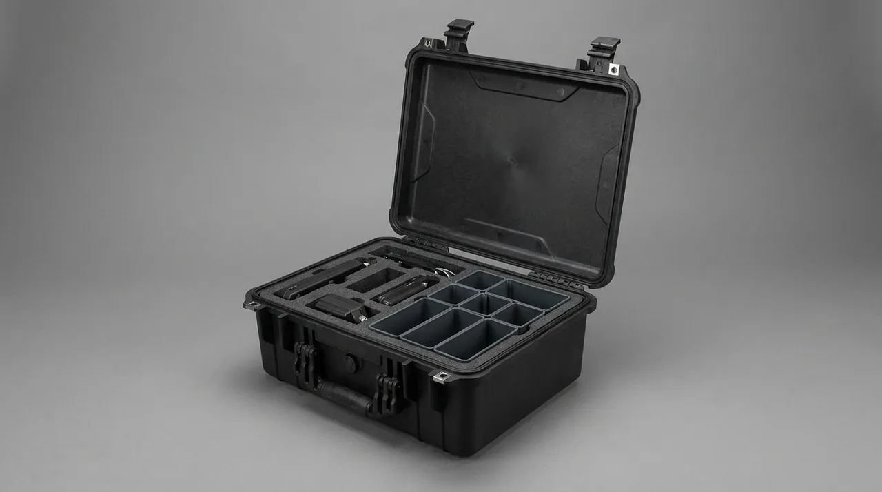
Isolation is one of the core features that distinguish a battery case from an ordinary storage box. Isolation refers to using physical structures to separate multiple payloads from each other, so they cannot collide, squeeze, or contact during transport. Common isolation methods include independent compartments, partition plates, elastic wrapping, and foam lining segmentation. Adequate clearance should be left between compartments to avoid friction between modules under vibration.
At the module level, isolation usually adopts a compartmentalized design, dividing one enclosure into several independent sub-spaces, each holding one module or a group of cells. This design reduces mutual interference and limits the scope of impact when one compartment experiences an anomaly. The partition plates should have certain stiffness to avoid collapse under stacking pressure.
Isolation design must also consider protection of terminals and connectors. The electrode terminals of the payload are the parts most in need of protection, and are usually covered with insulating caps, foam sleeves, or custom linings to prevent metal conductors from being exposed or accidentally contacted during transport. For custom linings, the cushioning and forming methods of a case foam lining can be referenced and cut precisely according to module shape.
From engineering practice, isolation is not the denser the better. Excessive isolation sacrifices space utilization and increases self-weight; insufficient isolation fails to handle impact. The reasonable approach is to determine compartment size and cushioning thickness based on module shape, weight, and transport mode, and to verify through drop and vibration tests at the sample stage. This is where a high-strength case structure adds value to safety design.
Selection of Internal Cushioning Systems
The lining is the part of the battery case that directly contacts the payload, and its cushioning performance determines the survival probability of modules under vibration and impact. Common lining materials include polyethylene foam, polyurethane sponge, cross-linked foam, and die-cut foam. Different materials vary in resilience, density, temperature resistance, and cost, and must be selected according to transport intensity.
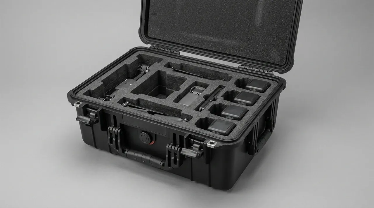
Polyethylene foam has a closed-cell structure and low water absorption, suitable for cushioning and isolation in general environments. Polyurethane sponge is highly soft with good conformability, often used for wrapping irregular shapes. Cross-linked foam performs better in temperature resistance and compression set, suited to occasions with higher stability requirements. Die-cut foam can achieve precise compartments through numerical control cutting, giving each module its own recess.
The determination of cushioning thickness should reference the transport vibration spectrum and drop height. As a general principle, heavier modules need thicker cushioning layers, and harsher transport conditions need higher resilience. When enclosure size is limited, double-layer foam or local thickening can enhance protection at critical locations. For grid cutting and thickness design, the engineering advice in custom foam factors can be consulted.
It must be emphasized that the lining must both cushion and fix. A qualified lining should prevent obvious displacement of modules in any orientation, without creating extra stress through over-tightness. In actual assembly, straps, hook-and-loop fasteners, or pressure covers are often combined to complete fixation. Fixing and cushioning are both indispensable; relying on only one is difficult to achieve ideal protection.
Temperature-Controlled Transport: Passive Insulation and Active Cooling
Temperature control is one of the most challenging aspects of battery case design. In terms of implementation, temperature control can be divided into passive insulation and active cooling. Passive insulation relies on enclosure insulation layers and phase-change materials to slow heat exchange, suitable for short trips or small temperature fluctuations. Active cooling maintains a set temperature through semiconductor cooling, insulated air ducts, or external cold sources, suitable for long trips or high-temperature environments.
The key to passive insulation lies in the thickness and continuity of the insulating material. The foam layer within the wall, the air gap between lining and outer wall, all slow heat conduction. Phase-change materials absorb or release heat within a specific temperature range, smoothing internal temperature fluctuations. This scheme is simple and needs no power, but has limited capacity under extreme temperature differences or long transport.
Active cooling must consider power supply and ventilation. If the battery case itself carries energy cells, in theory part of that electricity could drive a cooling unit, but this introduces complexity in wiring, heat dissipation, and isolation. Therefore, actively temperature-controlled cases often feature independent air ducts, temperature sensors, and display interfaces, and must stay consistent with the general principles in the temperature-controlled case guide.
Regardless of method, temperature control design must coordinate with sealing design. Full sealing helps dust and water protection but hinders heat dissipation; ventilation openings help dissipation but may admit dust and liquid. Mature schemes usually adopt dust-proof ventilation structures, such as labyrinth air ducts or filtered vents, minimizing foreign ingress while ensuring cooling.
Sealing Structure and Protection Rating
Sealing is the foundation for a battery case to achieve dust and water protection. A typical sealing structure consists of a lid frame edge, an elastic seal strip, and a compression mechanism. When the lid closes, the strip deforms under pressure and fills gaps, blocking external dust and liquid. The material, cross-section shape, and compression amount of the strip directly affect the final result.
In terms of protection rating, the international ingress protection code is commonly used to describe dust and water resistance. Taking IP67 as an example, it means complete dust protection and the ability to withstand short immersion at a certain depth without water ingress. For battery cases operating in humid, dusty, or coastal environments, achieving a higher rating is necessary. For the meaning of ratings and test boundaries, the relevant explanation in a waterproof case can be referenced.
Aging of the seal strip is an important factor affecting long-term protection performance. Rubber or thermoplastic elastomer gradually hardens or cracks under ultraviolet light, ozone, and temperature changes, so regular inspection and replacement are required. At the selection stage, materials with better weather resistance and lower compression set can be prioritized to extend maintenance intervals. This is closely related to the selection of a case seal strip.
Besides the material itself, the installation precision of the sealing structure is also critical. The strip must fit continuously without breakpoints, and corners need special cutting or integral molding to avoid leak channels. In mass production, sampling immersion tests should verify the sealing consistency of each batch, ensuring outgoing products meet the nominal rating.
Latch Configuration and Theft Resistance
Latches are the components that prevent accidental opening and theft of a battery case during storage and transport. Common latch forms include toggle latches, quarter-turn latches, compression latches, and latch loops that accept padlocks. For occasions requiring higher security, keyed or coded compression latches can be used, which generate extra clamping force when locked, combining sealing and theft resistance.
When selecting latches, convenience and security must be balanced. Frequently opened turnover cases suit quick toggles with padlocks, convenient yet providing basic theft resistance; long-term sealing or high-value payloads suit integrated compression latches. Latch materials are mainly stainless steel or surface-treated metal to resist salt spray and wear. The relevant configuration principles can be found in case hardware latch.
Theft resistance depends not only on the latch itself but also on the overall box structure. For example, the enclosure should have no weak gaps that can be pried open when locked, and latch points should be distributed at uniform force positions. For transporting high-value energy carriers, seal holes, lead-seal positions, or electronic tracking interfaces can be added to form dual physical and management protection.
In field or public transport scenarios, the anti-misoperation of latches should also be considered. Some latches feature anti-loosening structures that will not spring open under severe vibration, which is practically meaningful against vehicle bumps. Combining latches with stacking fixation avoids chain risks from box shifting during transport.
Stacking Load and Transport Fixation
Battery cases often need multi-layer stacking in storage and transport, so stacking load capacity is a non-negligible indicator. Stacking ability mainly relies on the corner structure and wall stiffness of the enclosure. Reinforcement ribs, stacking corners, and reasonable cross-section design can transfer upper-layer weight evenly to lower boxes, avoiding local collapse. For corner load bearing, refer to case stacking corner.
When stacking, total weight and center-of-gravity distribution must be noted. After loading energy carriers, the center of gravity should be as central and low as possible to reduce overturning risk. With many stacking layers, anti-slip and limit measures should be taken at the bottom, such as rubber pads, limit blocks, or straps, to prevent the whole stack from sliding during vehicle braking.
For transport fixation, battery cases in a carriage or hold should be constrained with straps, guide rails, or fixing frames. A freely moving box generates huge inertial force during emergency braking or turning, possibly damaging itself or surrounding equipment. The setting of fixation points should match enclosure structural strength to avoid deformation when tightened. This is also the significance of case rounded corner in anti-collision and stacking safety.
In addition, stacking and fixation must consider that heat dissipation channels are not blocked. If the battery case uses passive or active temperature control, the stacking method should leave space before and after ventilation openings, avoiding completely covering the heat dissipation surface against other boxes or the carriage wall. In actual loading schemes, temperature-controlled and non-temperature-controlled boxes are often arranged in layers to balance safety and space use.
Identification System and Traceability Management
Transport of energy cells has high requirements for identification, because the status information of the payload needs to be read by relevant personnel in time. The outside of a battery case usually has pasted or etched identification, including content category, state-of-charge prompt, no-inversion, moisture and shock warnings, as well as serial numbers and batch information. Clear identification reduces misoperation probability.
Traceability management relies on unique coding and a recording system. Each battery case and its internal modules should have corresponding numbers, registered during warehousing, transport, and handover. Thus, when a problem occurs, the specific batch and responsible person can be quickly located. For batch equipment support, this traceability is often more important than single protection performance.
Identification materials also need to adapt to the transport environment. Outdoor identification should be weather-resistant, tear-resistant, and solvent-resistant to avoid blurring from friction or liquid erosion. Etching, silk-screen printing, or riveted metal plates are more durable choices, while ordinary paper labels suit indoor turnover. Identification positions should avoid latches and sealing surfaces to prevent affecting structural function.
At the compliance level, identification should also meet the prompt requirements of relevant transport norms. Although this article does not discuss the physical and chemical properties or transport classification of specific payloads, as a container the external prompt information of the battery case should be consistent with the internal packing list, avoiding misjudgment from information mismatch. This shares ideas with the container identification approach of ADR IMDG hazmat transport.
Shell Materials: Metal and Engineering Plastics
The shell material of a battery case determines the basic strength, weight, and environmental resistance of the enclosure. Common shell materials include aluminum alloy, steel plate, and engineering plastics such as ABS, polypropylene, and polycarbonate. Metal materials have advantages in strength and impact resistance but are heavier and need corrosion protection; engineering plastics are light with high forming freedom but slightly lower stiffness under extreme loads.
Aluminum alloy enclosures have excellent stiffness-to-weight ratio and corrosion resistance, suitable for occasions sensitive to weight yet requiring sturdiness. Through profile splicing or sheet metal bending, a neat frame can be formed, then completed with corner pieces and a sealing frame. For battery cases used long-term in coastal or high-humidity environments, aluminum alloy is often a stable choice. For comparison, refer to aluminum case.
Engineering plastic enclosures mainly use injection or rotational molding, able to form complex shapes in one piece and naturally provide some insulation and corrosion resistance. ABS, polypropylene, and polycarbonate each have characteristics: the first has good rigidity and surface texture, the latter two excel in impact and temperature resistance. For material differences, consult protective case plastic materials and PP ABS PC case difference.
Shell material selection should also combine with internal temperature control and isolation requirements. For example, metal shells conduct heat quickly and need extra insulation in passive thermal design; plastic shells insulate well but require attention to material temperature limits in high-temperature environments. Regardless of material, necessary environmental adaptability verification should be passed to ensure no obvious performance decline within the target use range.
Influence of Molding Process on Structural Strength
The molding process of the shell directly determines the geometric accuracy and structural consistency of the enclosure. Injection molding suits mass production of dimensionally accurate, finely surfaced boxes, but tooling investment is high and part size is limited. Rotational molding can produce large, uniformly walled, seam-free enclosures with outstanding impact and weather performance. Each has applicable boundaries; see rotomold vs injection case.
Blow molding is often used for hollow shells, obtaining good stiffness thin-wall structures at lower cost, suitable for cost-sensitive standard cases. Composite molding uses fiber-reinforced resin to obtain ultra-high specific strength for professional occasions with harsh weight and strength requirements. For these processes, refer separately to blow molding case and composite molding case.
The molding process also affects subsequent reinforcement design. For example, integrating reinforcement ribs during injection or rotational molding can significantly improve bending and torsion resistance without extra welding or splicing. The direction, density, and height of ribs need to be determined with stress analysis, related to the ideas in case reinforcement ribs.
In addition, wall thickness uniformity is an important manifestation of process quality. Sudden wall thickness changes easily produce internal stress and sink marks, reducing long-term reliability. Through reasonable gate design and process parameter control, the enclosure can be thickened at critical stress locations and thinned at non-stress locations, achieving a balance of weight and strength. This is consistent with the principles discussed in case wall thickness strength.
Acceptance Criteria and Daily Maintenance
Before a battery case is put into use, it should pass acceptance to confirm that its structure, sealing, and lining status meet expectations. Acceptance usually includes appearance inspection, closure sealing check, stacking load sampling, and lining fit confirmation. For products with a nominal specific rating, corresponding immersion and dust verification should also be performed to ensure batch consistency.
Daily maintenance runs through the entire use cycle. Before and after each transport, check whether the seal strip is intact, the latch is flexible, and the lining is shifted or damaged. When aging strips, stuck latch tongues, or collapsed foam are found, replace the corresponding parts promptly to avoid small problems evolving into protection failure. For seal maintenance, combine with case seal strip.
Environmental adaptability maintenance is also important. Battery cases used in coastal or chemical areas should be cleaned of salt and dirt regularly to prevent corrosion accumulation. During long-term storage, place them in a dry and ventilated place, keeping the lid slightly open or with desiccant to avoid internal moisture accumulation. For boxes with temperature control or sensing interfaces, also check the dust-proof cover and cable integrity.
Records support maintenance work. It is recommended to establish a usage file for each battery case, recording transport mileage, drop or impact events, and maintenance replacements. These data help predict component life and provide objective basis when disputes arise. Combining maintenance with identification traceability forms a closed-loop management.
Integration with General Equipment Cases
In equipment support systems, battery cases rarely exist in isolation; they often need to cooperate with communication, maintenance, and command cases. The key to integration is dimensional standardization and interface compatibility. When various protective cases adopt consistent external dimension modules and stacking structures, they can be quickly combined into functionally complete support units on a transport platform.
For example, in a power support convoy, a battery case can be arranged alongside a power distribution cabinet case, the former providing energy reserve and the latter completing power distribution; combined with a portable power station case as flexible supplement, a cascaded power supply capability is formed. This combination improves space utilization and simplifies field deployment.
In communication scenarios, a battery case can dock with equipment racks inside a communication shelter case through standardized cable channels to complete power connection. At this time, the positioning, fixation, and heat dissipation of the battery case need to be coordinated within the overall shelter layout to avoid local overheating or vibration transmission.
Integration is also reflected at the information management level. When multiple cases have a unified identification and coding system, commanders can see the position, status, and content of each box in the scheduling system, achieving refined support. This systemic benefit from container standardization is often more valuable than a single-box performance improvement.
Selection Checklist and Procurement Advice
When procuring a battery case, it is recommended to start from the use scenario, clarify the transport mode, environmental temperature and humidity, stacking layers, and turnover frequency, then determine shell material, protection rating, and lining form. Comparing prices without a clear scenario often leads to either insufficient protection or over-configuration. Establishing a scenario-based selection checklist can significantly improve decision efficiency.
Secondly, suppliers should be required to provide verifiable performance evidence, including protection rating test reports, stacking load data, and lining cushioning scheme descriptions. For critical uses, samples should be arranged for actual drop and vibration tests to verify whether manufacturer claims are true. If necessary, the test ideas in MIL-STD-810H case compliance can be referenced to formulate acceptance schemes.
Thirdly, the whole-life-cycle cost should be comprehensively considered. A battery case with slightly higher initial price but durable sealing, replaceable lining, and maintainable structure is often more economical than a cheap but fragile product. During procurement, maintenance convenience, spare part availability, and manufacturer service capability can be included as scoring items, not just unit price.
Finally, do not ignore integration and traceability needs. If the battery case will be incorporated into a larger equipment case system, confirm in advance whether dimension modules, stacking interfaces, and identification norms are compatible. For occasions requiring frequent cross-unit handover, clarify coding rules and record formats to lay a foundation for subsequent management.
Frequently Asked Questions
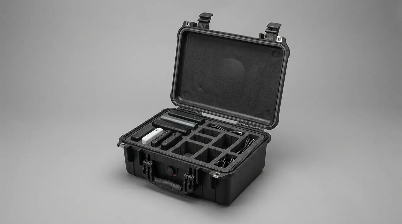
Q: What is the main difference between a battery case and a general equipment case? A: A battery case differs from a general equipment case in internal space planning, isolation structure, ventilation, and temperature control interfaces. A general case focuses on universal storage and basic protection, while a battery case must provide physical separation between individual cells or modules, insulating wraps that prevent accidental terminal contact, and optional passive insulation or active cooling channels for energy carriers. In addition, a battery case often reserves status identification and traceability coding positions to facilitate reading information during transport and handover. Understanding this difference helps avoid misusing an ordinary storage box for energy carriers, which would leave isolation and temperature control insufficient. The distinction also shapes the selection of lining, sealing, and stacking features that a true battery case must carry from the start of design. When planning a support system, designers should treat the battery case as a specialized container rather than a generic box with extra padding. This perspective also simplifies spare parts planning and crew training, because teams learn one clear rule: energy carriers receive dedicated isolation while generic gear uses standard compartments. Treating the two container types separately reduces configuration errors during high-pressure field deployments.
Q: How do I determine the protection rating needed for a battery case? A: The protection rating should be determined according to the actual use environment. If the case only turns over indoors or in a dry carriage, basic dust protection is sufficient; if it must operate in dusty, humid, or splash-prone field environments, a higher dust and water rating should be considered. When determining the rating, comprehensively judge based on weather, road surface, and operation mode along the transport route, rather than blindly pursuing the highest rating. Achieving a high rating usually means tighter sealing, possibly unfavorable to heat dissipation, so it must be weighed with temperature control design. It is recommended to reference successful cases in similar scenarios and conduct immersion and dust verification at the sample stage, then document the chosen rating for traceability across the whole fleet of cases. Procurement teams should also align the rating with the real failure modes they expect, not with marketing numbers alone not with marketing numbers alone. A rating chosen this way stays credible during audits and reduces the risk of both over-engineering and dangerous under-protection.
Q: Is thicker foam lining always better for a battery case? A: Foam lining is not the thicker the better. Insufficient thickness cannot absorb impact, but excessive thickening occupies internal space, increases self-weight, and may make modules too tight inside and subject to extra stress. Reasonable thickness should be calculated based on module weight, transport vibration spectrum, and expected drop height, then calibrated through sample drop tests. In practice, zonal thickness design is often adopted, thickening at critical stress locations and thinning at non-stress locations. At the same time, the lining must both cushion and fix modules so they do not shift obviously in any orientation, and fixing and cushioning must be considered together to avoid premature fatigue of the foam under repeated field use. A well-designed lining uses density gradients and cutouts rather than uniform bulk, which keeps the container light while still protecting the payload through every expected handling event through every expected handling event. Reviewing the lining after a few real missions then reveals where further tuning pays off most.
Q: How should I choose between passive insulation and active cooling? A: Passive insulation relies on insulation layers and phase-change materials to slow heat exchange; it is simple and needs no power, suitable for short trips or small temperature differences. Active cooling maintains a set temperature through semiconductor cooling, air ducts, or external cold sources, suitable for long trips, high temperatures, or temperature-sensitive environments, but brings complexity in power supply, wiring, heat dissipation, and isolation. The choice should evaluate transport duration, extreme environmental temperature, and whether power supply conditions exist. To balance both, limited active ventilation can be added on top of passive insulation, combined with dust-proof ventilation structures to reconcile cooling with dust and water protection, which keeps the container practical for mixed field conditions. A staged design that starts passive and adds active only where the route demands it usually costs less than a fully active system built for the worst case built for the worst case. This avoids paying for cooling capacity that the actual route never demands from the container.
Q: What are the safety points when stacking battery cases? A: Stacking safety first depends on the corner structure and wall stiffness of the enclosure; reinforcement ribs and stacking corners can transfer upper-layer weight evenly. After loading, the center of gravity should be as central and low as possible to reduce overturning risk. With multiple stacking layers, anti-slip pads, limit blocks, or straps should be used at the bottom to prevent the whole stack from sliding. During transport, boxes must be constrained with straps or fixing frames to avoid inertial impact during emergency braking or turning. In addition, if the battery case has temperature control, stacking should leave space before and after ventilation openings to avoid completely covering the heat dissipation surface and affecting temperature control performance during long-haul movement. Field crews should also inspect the stacking corners before each load to confirm no crack has formed that would redistribute weight unevenly redistribute weight unevenly. A simple pre-load check takes minutes and prevents a slow failure that would only appear after many shipments.
Q: How often should the seal strip be replaced? A: The replacement interval of a seal strip depends on material weather resistance and usage frequency. In environments with strong ultraviolet light, heavy salt spray, or large temperature differences, rubber or thermoplastic elastomer hardens and cracks faster and may need more frequent inspection and replacement. Generally, visual inspection before and after each transport is recommended; replace immediately when hardening, cracking, permanent flattening, or breakpoints are found. Prioritizing materials with low compression set and good weather resistance can extend maintenance intervals. In batch use, sampling immersion tests should verify sealing consistency to ensure each outgoing batch meets the nominal rating, and a spare strip inventory should be kept ready for field service. Records of each inspection should be attached to the case identity so that trend analysis can predict the next replacement before failure occurs in the field before failure occurs in the field. Such disciplined upkeep keeps the rated protection genuine instead of merely printed on the label.
Q: What types of energy carriers can a battery case hold? A: From the container perspective, a battery case can hold individual cells, battery modules, portable storage power sources, and uninterruptible power supply battery packs, among energy carriers that must maintain status stability during transport. However, this article discusses only the enclosure structure as a packaging and protection container, and does not address the physical and chemical properties, formulations, or internal structures of any contents. Whether a specific energy carrier can be loaded, how to isolate and identify it, should be based on local regulations, transport norms, and manufacturer instructions. As a container supplier, we focus on providing a controlled, isolated, and traceable storage environment that supports safe handling regardless of the specific payload class involved. Users remain responsible for confirming that their chosen contents comply with all applicable transport and storage rules before shipment before shipment. Documenting the load plan also helps downstream handlers respect the same isolation rules without guesswork.
Q: How can procurement verify the performance claimed by manufacturers? A: Procurement verification should start from both documents and physical samples. On the document side, require manufacturers to provide protection rating test reports, stacking load data, and lining cushioning scheme descriptions; on the physical side, arrange sample drop, vibration, and immersion tests for critical uses to check whether claims are true. The test ideas in relevant MIL-STD-810H compliance can be referenced to improve test targeting. In addition, maintenance convenience, spare part availability, and service capability should be included as scoring items rather than just unit price, and a usage file should record transport and maintenance to support long-term reliability evaluation across the purchased fleet. A short acceptance checklist signed by both parties prevents vague claims from passing as verified performance during later disputes.
*This article discusses only packaging and protective containers from an engineering standpoint. Compliance with local regulations, transport norms, and applicable export controls remains the responsibility of the user and should be confirmed before any deployment or shipment.*