

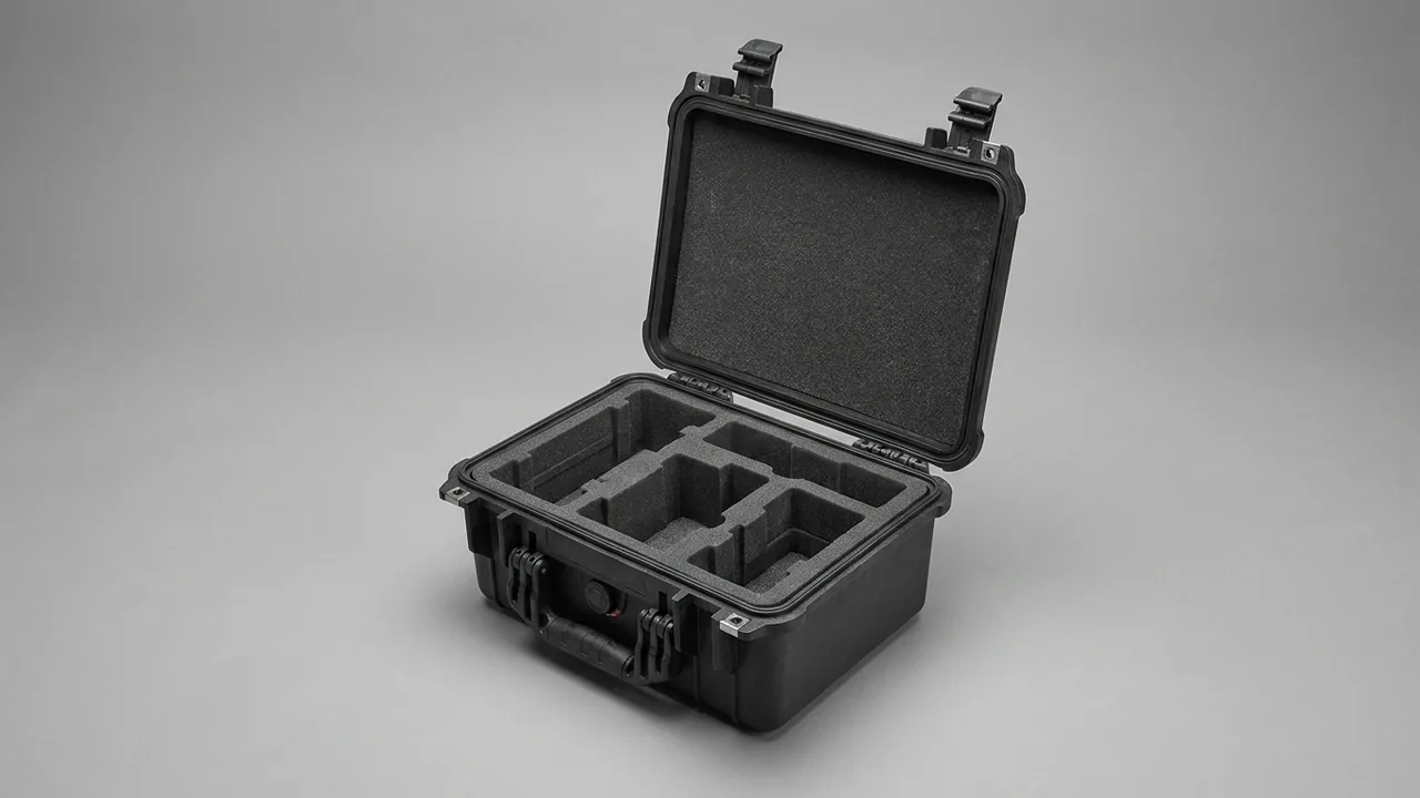
General-purpose equipment is the most underestimated category in protective packaging. It has no single defined model like a drone and no explicit regulatory framework like medical devices, yet the range of scenarios it covers is broader than either. An infrared camera used for inspections may be at a substation on Monday and on an offshore platform on Friday. A measurement kit may travel by truck, then by aircraft, then up three flights of stairs on someone's shoulder. A batch of field trial gear may share one case through sunlight, rain, dust, and repeated loading. What these items have in common is real value, widely varying mass, and a transport chain with nobody watching.
What determines whether this gear still works on arrival is not one extreme journey but cumulative effects: compressed padding, aged gaskets, loosened latches, relaxed fastener preload, collapsed liner pockets. JUNZHIJIA designs general equipment cases around a single position: the value of a protective case is that it turns transport risk into engineering parameters that can be calculated, verified, and reused, rather than into a thicker box.
Table of Contents
- Positioning a General Equipment Case: From Fit to Control
- Payload Spectrum and Risk Grading
- Shell Routes: Injection PP, Rotomolded PE, Aluminum
- Sealing Ratings: The Logic Behind IP54 to IP67
- Cushioning: Matching Allowable Acceleration to Stroke
- Liner Systems: EVA, EPE, IXPE, and Rigid Foam
- Cavities, Positive Stops, and Center of Gravity
- Pressure Equalization Valves and Thermal Opening
- Latches, Hinges, and Stacking Load
- Transport Testing and Verification Methods
- Salt Fog, Humid Heat, Dust, and Ultraviolet
- Reusable Design and Return Transport
- Customization Workflow and Acceptance Checklist
- Frequently Asked Questions FAQ
- Conclusion and Related Reading
Positioning a General Equipment Case: From Fit to Control
The most common failure in general equipment cases is not insufficient strength but management failure. Five patterns recur.
"It fits, but nobody remembers." Only the person who packed the case knows what went in, how many pieces, and which are matched sets. After staff rotation the list is lost, retrieval becomes a search, and return becomes guesswork.
"It fits, but nothing is secure." Pockets are cut to the largest item, smaller items rattle, and the result is rub marks, worn paint, and cracked joints.
"The rating is fine, but it is not used correctly." A case rated IP67 with unengaged latches, grit on the gasket, or an unreseated equalization valve performs near IP54 in practice.
"It survives drops but not stacking." The drop test passes, then months of stacking in stores and trucks bulge the side walls and distort the sealing face.
"It is used once and then unusable." The shell is intact, but the liner has collapsed, the gasket hardened, and the desiccant is spent, so the case no longer protects anything.
| Symptom | Root cause | Engineering response | Management response |
|---|---|---|---|
| --- | --- | --- | --- |
| Nobody remembers | No fixed positions or list | One item per cell, visible gaps | In-case list and numbering |
| Nothing secure | Pockets cut to the largest item | Per-item pockets, 2–4 mm preload | Standardized packing procedure |
| Rating not used | No closing check | Continuous witness mark, reseated valve | Formalized three-point closing check |
| Fails stacking | Insufficient wall stiffness | Ribs and double-wall construction | Limit stack height and duration |
| Unusable after one use | No consumable plan | Removable liner, replaceable gasket | Maintain a case log |
Starting from this table avoids the usual mistake of choosing a case by appearance and price, then trying to bolt on the management requirements afterwards. The correct order is to define the payload, the transport chain, and the management requirements first, and derive the structure from them.
Payload Spectrum and Risk Grading
The payload range is enormous, from a 0.5 kg sensor to an 80 kg cabinet module. Four classification axes work well: mass, fragility, environmental sensitivity, and handling frequency.
Mass drives the bearing layer and carrying method. Fragility drives cushioning stroke. Environmental sensitivity drives sealing and thermal requirements. Handling frequency drives hardware grade and liner abrasion resistance.
| Grade | Typical mass | Typical items | Cushioning approach | Carrying method |
|---|---|---|---|---|
| --- | --- | --- | --- | --- |
| L1 Light and fragile | Under 2 kg | Sensors, optical modules, probes | Low density, long stroke | Hand carry |
| L2 Standard | 2–10 kg | Handheld instruments, controllers, power supplies | Medium density, layered | Hand carry |
| L3 Heavy and rigid | 10–30 kg | Chassis, pump sets, motors | High density plus positive stops | Two-person lift or wheels |
| L4 Very heavy | 30–80 kg | Cabinet modules, complete systems | High density plus rigid bearing plate | Forklift or hoist |
| L5 Irregular | Any | Long rods, discs, tube bundles | Continuous cradles, never unsupported | Depends on mass |
Grading is followed by risk profiling: each grade maps to specific risk sources, and each risk source maps to specific engineering measures. L1 items are dominated by resonance and fretting, so the answer is full attitude constraint plus a curved cradle. L3 items are dominated by displacement and local indentation, so the answer is corner stops plus a high-density bearing layer.
| Risk source | Trigger | Symptom | Applies to | Countermeasure |
|---|---|---|---|---|
| --- | --- | --- | --- | --- |
| Drop impact | Loading, handling slips | Shell cracks, internal displacement | L1–L5 | Graded cushioning plus stops |
| Resonance and fretting | Long road or off-road haul | Loosened fasteners, rub marks | L1–L3 | High-damping liner, full contact |
| Stacking crush | Stores and vehicle stacking | Wall bulging, seal distortion | L2–L5 | Ribbing plus height limits |
| Thermal and humidity cycling | Day-night swings, crossing climates | Condensation, mold, aging | L1–L5 | Sealing, desiccant, valve |
| Dust ingress | Desert, machining areas | Sticky slides, worn contacts | L1–L5 | Dust-tight construction |
| Handling error | One-hand opening, forced closure | Lid slams, gear pinched | L1–L5 | Limited hinges, paired latches |
Shell Routes: Injection PP, Rotomolded PE, Aluminum
Shell selection balances four variables: weight, strength, cost, and internal structuring flexibility. There is no universally best answer.
Injection-molded PP is formed in one shot with uniform walls and high accuracy, and ribs, handles, latch seats, and compartment skeletons can be molded in. It is light, consistent, and cheaper at volume, which suits gear carried by hand. The limits are tooling cost and part size.
Rotomolded PE is seamless with walls of 6–12 mm and excellent drop and crush resistance, which suits heavy and frequently handled gear that may be treated roughly. The trade-offs are weight, a rougher finish, and wider tolerance.
Aluminum extrusion combines profile frames and panels for high stiffness, rectilinear geometry, and easy internal layering with drawer slides. Its thermal performance suits continuously heat-generating equipment, at the cost of the highest weight at a given rating.
Stainless steel serves extreme corrosion or cleanroom duty with the best strength and corrosion resistance, but at the highest weight and cost.
| Shell route | Impact | Weight | Dimensional accuracy | Tooling | Fit |
|---|---|---|---|---|---|
| --- | --- | --- | --- | --- | --- |
| Injection PP | Medium | Light | High | High | L1–L3 |
| Rotomolded PE | High | Heavy | Medium | Medium | L2–L5 |
| Aluminum extrusion | Medium-high | Heaviest | High | Low | L2–L5, heat-generating gear |
| Stainless steel | High | Heaviest | High | Medium | Corrosive, clean environments |
The practical criterion is fully loaded mass against carrying method. A comfortable one-handed limit is roughly 10% to 15% of body weight; beyond that, wheels or a two-person lift are required by design, not by preference. Process comparisons appear in rotomolding versus injection molding and engineering plastic outdoor case characteristics.
Sealing Ratings: The Logic Behind IP54 to IP67
Ingress protection follows IEC 60529 or GB/T 4208. The principle is not "higher is better" but "matched to exposure with margin."
| Rating | Dust | Water | Key test conditions | Typical fit |
|---|---|---|---|---|
| --- | --- | --- | --- | --- |
| IP54 | Limited | Splashing | Splash from all directions | Indoor, dry shops |
| IP55 | Limited | Water jets | 6.3 mm nozzle | Indoor with washdown |
| IP65 | Dust-tight | Water jets | 6.3 mm nozzle, about 12.5 L/min | General outdoor use |
| IP66 | Dust-tight | Powerful jets | 12.5 mm nozzle, about 100 L/min | Decks, heavy rain |
| IP67 | Dust-tight | Temporary immersion | 1 m depth, 30 minutes | Water crossings, emergency work |
Three questions settle it: is the equipment dust-sensitive, will it be exposed to rain, and will it contact flowing or standing water? In practice dust exclusion usually matters more than water, because fine particles reaching slides, latches, and bearings cause continuous abrasive wear, while brief rain mostly affects surfaces.
For high-value or failure-critical equipment, design the system-level IP solution: treat gasket, latches, valve, and cable glands as one sealing system rather than separate specifications. Related methods appear in system-level IP67 design and dustproof design for outdoor cases.
Remember that the rating belongs to the complete case system. Unengaged latches, grit on the gasket, an unreseated valve, or an unsealed cable gland all reduce real protection substantially, which is why the three-point closing check is a process control rather than an optional nicety.
Cushioning: Matching Allowable Acceleration to Stroke
Cushioning design does not begin with material selection but with allowable acceleration: the peak acceleration the equipment can take without functional or accuracy damage. This usually comes from the manufacturer or from validated field data.
With that value established, the required stroke follows. The governing relationship is simple: for a given impact energy, a longer stroke produces a lower peak acceleration. Light fragile items therefore get low density and long stroke, while heavy rigid items get high density and short stroke.
| Grade | Allowable acceleration | Recommended density | Recommended thickness | Structural point |
|---|---|---|---|---|
| --- | --- | --- | --- | --- |
| L1 Light and fragile | Low | 38–45 kg/m³ | 30–50 mm | Curved cradle, full attitude constraint |
| L2 Standard | Medium | 45–60 kg/m³ | 20–40 mm | Layered pockets, base bearing |
| L3 Heavy and rigid | Medium-high | 60–80 kg/m³ | 15–30 mm | Corner stops, rigid bearing |
| L4 Very heavy | High | High density plus rigid foam | By structure | Bearing plate plus tie-downs |
| L5 Irregular | Depends on item | Medium density plus IXPE | Continuous cradle | No unsupported span |
Multi-layer construction is standard: a high-density base bears the load, a medium-density middle layer holds the cut pockets, and a soft lid layer applies preload. This hard-base, medium-core, soft-cap arrangement lets items of different mass each receive reasonably matched cushioning within one case. The general method is covered in precision instrument protective case design.
One reminder: vibration over a long haul is often more destructive than a single drop. If the equipment retains any small degree of freedom, vehicle vibration gradually relaxes fastener preload, which shows up as "it powered up fine, but failed after running for a while." Constraint completeness therefore deserves more investment than cushioning thickness.
Liner Systems: EVA, EPE, IXPE, and Rigid Foam
Each liner material has a defined role, and mixing them up leaves a gap somewhere.
EVA is the workhorse: density is adjustable, it cuts cleanly, and it is closed-cell and non-absorbent. General equipment cases typically use 45–70 kg/m³; higher density means more compressive strength but a shorter stroke.
EPE is softer, lighter, and more resilient, suiting lid preload layers and void filling, but its low tear strength makes it unsuitable for deep pockets.
IXPE has fine cells and a flat surface at 1–3 mm, used to wrap curved parts, suppress fretting, and avoid witness marks.
Rigid foam such as cross-linked or high-density PE offers strong support with almost no compression, suiting structural fill and bearing plates, but with poor cushioning.
| Material | Density | Primary role | Thickness | Caution |
|---|---|---|---|---|
| --- | --- | --- | --- | --- |
| Medium-density EVA | 45–60 kg/m³ | Cut locating pockets | 20–60 mm | Seal cut faces |
| High-density EVA | 65–80 kg/m³ | Base bearing layer | 15–30 mm | Too hard shortens stroke |
| EPE | 20–30 kg/m³ | Lid cushion, void fill | 10–40 mm | Never used for deep pockets |
| IXPE | 30–50 kg/m³ | Conformal wrap | 1–3 mm | Needs reliable adhesive |
| Rigid PE foam | 30–45 kg/m³ | Structural fill | 30–100 mm | Strong support, poor cushioning |
Quantitative comparisons appear in protective case foam material comparison and liner foam types explained.
Cavities, Positive Stops, and Center of Gravity
Cavity design gives every item exactly one place while keeping the loaded case balanced for carrying.
Three cavity rules apply: heavy items low, frequently used items outward, and sharp corners never sharing a cavity with precision items. For matched equipment sets such as a multi-module measurement system, arrange by functional chain rather than by volume, so the retrieval order matches the order of use.
Positive stops require every item to be constrained in at least two directions rather than resting on a base alone. Corner blocks are the lowest-cost way to raise restraint effectiveness, especially for L3 and L4 items.
Center of gravity must sit over the handle or the wheel load axis. A case that carries off-balance causes rapid fatigue in one-handed use and is more likely to be set down on a corner.
| Design element | Objective | Implementation | Common error |
|---|---|---|---|
| --- | --- | --- | --- |
| Cavities | One item, one place | Per-item pockets plus dividers | One large mixed cavity |
| Positive stops | Six-direction restraint | Corner blocks plus preload | Base support only |
| Grab clearances | One-hand removal | 15–25 mm finger allowance | Pockets cut too tight |
| Center of gravity | Over the load axis | Heavy items low and central | Batteries or heavy items in one corner |
| Serviceability | Removable liner | Tray or stacked insert | Permanently bonded liner |
| Expansion | Room for new items | 5%–10% margin | Layout packed solid |
Removable divider systems add flexibility at low cost; see removable divider system design.

Pressure Equalization Valves and Thermal Opening
A sealed case inevitably develops a pressure differential as temperature changes. Heated in the sun, internal air expands, lifting the lid and loading the latches. Cooled at night or moved into air conditioning, internal negative pressure forms, making the lid hard to open and, more seriously, drawing external moisture into any imperfect seal.
A pressure equalization valve opens briefly above a threshold and then reseals, and in a properly designed unit the valve body incorporates a waterproof breathable membrane that does not reduce the case's ingress protection while closed.
| Valve parameter | Influence | Design guidance | Consequence of failure |
|---|---|---|---|
| --- | --- | --- | --- |
| Cracking pressure | When relief occurs | Set for worst-case temperature | Suction at opening |
| Airflow capacity | How fast it balances | Matched to case volume | Slow balancing, hard opening |
| Membrane water rating | Protection while open | Not below the case rating | Water entry during relief |
| Closed-state sealing | Protection while closed | Self-reseating, no debris | Open state admits dust and water |
| Contamination resistance | Long-term reliability | Dust-resistant, cleanable | Grit jams the diaphragm |
Maintenance is simple: after every outdoor job, check that the diaphragm is not jammed by dust and that it reseats automatically. A valve left open or blocked drops the protection level immediately. The mechanism is described in how a pressure equalization valve works.
Latches, Hinges, and Stacking Load
These three components decide reliability in use rather than in the test lab.
Latches need symmetrical placement, a positive closing feel, and anti-accidental-opening features. Above about 500 mm of case length, one latch per side cannot distribute compression evenly around the sealing perimeter, so two or more pairs are normal. The most direct proof of engagement is a continuous compression witness on the sealing face.
Hinges must support the lid's own weight and limit opening, so wind or incidental contact cannot slam the lid back onto the equipment. On large cases the hinge-to-shell junction is a classic stress concentration point and usually needs reinforcement.
Stacking load is governed by wall and lid compressive stiffness. Upper cases transfer weight through corners and walls, and insufficient stiffness bulges the walls inward until the sealing face distorts. Establishing a stacking height combines loaded mass, storage temperature, since heat lowers the elastic modulus of plastics, and permitted duration.
| Component | Key metric | Verification | Consequence of failure |
|---|---|---|---|
| --- | --- | --- | --- |
| Latch | Holding force, cycle life | Inspect after 500 cycles | Pops open in transit |
| Hinge | Load, opening stop | Static hang test, loaded lid | Lid slams back |
| Handle | Static load, grip | Hang test at twice rated load | Fracture, pinched fingers |
| Wheels | Load, wear | Loaded towing over set distance | Axle seizure |
| Gasket | Compression, aging | Witness mark plus spray test | Water and dust ingress |
| Valve | Cracking pressure, reseating | Opening force after thermal cycling | Suction or pop at opening |

Transport Testing and Verification Methods
Validation exists to prove that this case and equipment combination survives the intended chain, not to obtain a certificate, so the plan must map to the real route.
| Test | Reference | Key conditions | Acceptance |
|---|---|---|---|
| --- | --- | --- | --- |
| Drop | ISTA series, GB/T 4857.5 | Corner, edge, face drops | No rupture, no equipment shift |
| Random vibration | ASTM D4169, GB/T 4857.7 | Spectrum by transport mode | No loosening, no abnormal noise |
| Fixed-frequency vibration | GB/T 4857.7 | Set frequency and duration | No liner powdering, no rub marks |
| Stacking | GB/T 4857.3 | Constant load, defined time | No bulging, sealing face intact |
| Concentrated impact | ASTM D4169 procedures | Specified impact energy | No liner penetration, no damage |
| Spray and immersion | IEC 60529 | Conditions for the declared rating | No internal water |
| Low pressure | Relevant procedures | Simulated air freight altitude | Sealing intact, no deformation |
| Salt fog | GB/T 10125 | Neutral spray, defined duration | No red rust as agreed |
Acceptance operates on three levels: physical integrity, function and accuracy confirmed after testing, and traceability in which records, equipment serial numbers, and pre- and post-test data correspond and are archived.
Any test is conducted under specific conditions, and real routes may include uncovered stages such as repeated transshipment handling, extreme temperatures, or extended stacking. Before volume deployment, run a physical trial on one representative route with shock and climate loggers, then compare the captured data against the tested conditions. Cross-border routes should also consider the sea leg; see sea freight and long-haul transport of outdoor cases.
Salt Fog, Humid Heat, Dust, and Ultraviolet
General equipment cases often work across climates, and combined exposures are more destructive than any single factor.
Salt fog mainly attacks metal components: latch rivets, hinges, valve bodies, and the profiles and corner castings of aluminum cases. It destroys the passive film and initiates pitting and galvanic corrosion. GB/T 10125 defines the neutral spray method, but test duration does not convert simply into service life, which depends on salt concentration, wet-dry cycling, temperature, and maintenance; treating hours as years is unsound.
Humid heat and condensation are the more realistic threat. Heating by day expands and vents the internal air; cooling at night creates negative pressure, and if sealing is imperfect, external moisture enters and condenses, eventually wetting circuit boards, oxidizing connectors, and fostering mold inside lens assemblies.
Dust dominates in desert, cement, and metalworking environments, where fine particles entering slides, latches, and bearings cause abrasive wear that is hard to remove.
Ultraviolet and ozone chalk, embrittle, and fade plastic surfaces. Cases that stay outdoors long term should use UV-stabilized material and avoid prolonged direct exposure.
| Environment | Primary threat | Protection measure | Maintenance action |
|---|---|---|---|
| --- | --- | --- | --- |
| Coastal salt fog | Metal corrosion | Corrosion-resistant hardware, sealed shell | Rinse exterior after work |
| Humid tropics | Condensation, mold | Desiccant bay plus sealing | Replace desiccant on schedule |
| Desert dust | Fine particle ingress | Dust-tight construction, gaskets | Wipe the case before opening |
| Cold highlands | Brittle material, hard gaskets | Low-temperature rated materials | Avoid violent opening when cold |
| Long outdoor deployment | UV chalking, fading | UV-stabilized material, shade storage | Inspect surface periodically |
Reusable Design and Return Transport
The fundamental difference between an equipment case and disposable packaging is reuse, which adds two requirements: durability and return logistics.
Durability touches three areas: hardware specified by cycle count, a liner designed for replacement, and gaskets managed as consumables. A common error is designing the liner to single-trip standards, so pockets collapse by the third trip.
Return transport requires the case to stack, fold, or nest reliably when empty, otherwise return cost rises sharply. Common measures include aligned top and bottom faces for empty stacking, removable liners that stack separately, and base dimensions matched to pallet modules.
| Reuse factor | Design requirement | Management requirement |
|---|---|---|
| --- | --- | --- |
| Hardware life | Specified by expected cycle count | Periodic latch and hinge checks |
| Liner replacement | Removable, separately purchasable | Scheduled replacement in the case log |
| Gasket replacement | Individually removable | Record replacement dates |
| Empty stacking | Stable when stacked empty | Limit stack height |
| Pallet compatibility | Base matched to pallet module | Faster handling |
| Return tracking | Durable numbering and marking | Log destinations |
Related approaches appear in reusable transit case design and advantages of PP outdoor cases.
Customization Workflow and Acceptance Checklist
The workflow can be summarized in seven stages. Payload list and grading defines items, quantities, masses, dimensions, and L1–L5 grades. Risk profiling maps the transport chain, environment, and management requirements into a risk-to-measure table. Shell and rating selection sets the route and ingress level from loaded mass, carrying method, and exposure. Structural design produces cavities, stops, center of gravity, liner layering, and pockets, with a layout drawing. First-article fitting builds the prototype liner, loads the real equipment, and verifies handling, preload, and lid closure. Verification testing runs drop, vibration, and spray tests as agreed. Production and documentation delivers batch liners with critical dimension re-inspection plus case documents.
| Stage | Deliverable | Customer confirmation | Common rework point |
|---|---|---|---|
| --- | --- | --- | --- |
| List and grading | List and grading table | Completeness | Accessories and consumables omitted |
| Risk profiling | Risk-to-measure table | Realism of the transport chain | Rough handling underestimated |
| Selection | Shell and rating proposal | Loaded mass, carrying method | Carry limit ignored |
| Design | Layout and exploded drawings | Grab clearances, preload | Grab position pinches fingers |
| First article | Prototype liner and fit record | Handling is comfortable | Insufficient preload |
| Verification | Test report | Acceptance criteria | No physical road trial |
| Production | Shipping report and documents | Critical dimension sampling | Batch colour variation |
Acceptance should be a physical exercise.
| No. | Check item | Acceptance criterion | Action if failed |
|---|---|---|---|
| --- | --- | --- | --- |
| 1 | Shell appearance | No cracks, distortion, sharp edges | Reject or replace |
| 2 | Gasket | Seated, untwisted, continuous witness | Reseat |
| 3 | Latches | Symmetrical engagement, no binding | Adjust or replace |
| 4 | Equalization valve | Opens and closes, no leak when closed | Inspect reseating |
| 5 | Liner pockets | Conformal, no interference, 2–4 mm preload | Rework liner |
| 6 | Cavities and stops | Six-direction restraint, no movement when shaken | Add stop blocks |
| 7 | Center of gravity | Over the load axis, one-hand carry possible | Rebalance the layout |
| 8 | Spray test | No internal water or damp liner | Inspect sealing face |
| 9 | Stacking test | No bulging or collapse | Add ribbing |
| 10 | Documentation | List, layout drawing, care card present | Supply missing items |
Frequently Asked Questions FAQ
Q: Is the highest available ingress rating always the safest choice for an equipment case?
A: Not necessarily, and it helps to separate the rating from actual protection. Under IEC 60529 or GB/T 4208, IP67 adds temporary immersion protection, which is genuinely valuable only where equipment may contact standing or flowing water. If the real chain is ordinary outdoor use with brief rain, IP65 is sufficient and the saved budget is better spent on a better liner and better hardware. More importantly, a higher nominal rating does not translate automatically into real protection: unengaged latches, grit on the gasket, or an unreseated equalization valve will each reduce actual protection well below the label, potentially below IP54. General equipment cases are opened frequently, so these conditions are common rather than exceptional. The right sequence is to set the rating from the exposure scenario, then formalize a three-point closing check, and finally put gaskets and valves on an inspection and replacement schedule so the rating is maintained by process rather than assumed from the label. Where the payload includes several critical instruments, a second case used only for those instruments is cheaper than the consequences of a shared cavity.
Q: My equipment passed a drop test, so why did it still fail after a long road trip?
A: Because drop testing and long-haul vibration exercise completely different failure mechanisms. A drop is short and high-amplitude, causing rupture and immediate displacement. Long-haul vibration is sustained and low-amplitude, causing fastener preload relaxation, ribbon and cable fatigue near anchor points, and fretting wear between the liner and the equipment. Passing a drop test only shows that the shell did not rupture in one event; it says nothing about whether the equipment has any freedom inside the liner. If a pocket is oversized by 1–2 mm, the equipment sits semi-free throughout the journey, and after a few hundred kilometers the symptoms appear as sensor drift or intermittent connector contact, which present as "it powers up but misbehaves." The remedy is more constraint rather than more thickness: tighten pocket clearance, increase preload, provide continuous cradles for slender items, and run a physical road trial with an accelerometer during first-article development. Comparing the recorded spectrum against the liner density then tells you whether to add a damping layer or simply tighten the pockets.
Q: Should the liner be EVA or EPE, and is mixing materials a problem?
A: Mixing is not a problem; it is the recommended approach, provided each material does the job it is best at. EVA has adjustable density, good compressive and tear performance, and stable cut faces, which suits pocket cutting and load bearing. EPE is softer, lighter, and more resilient, which suits lid preload layers and void filling, but its low tear strength means deep pockets tend to tear and propagate in service. IXPE has fine cells and a flat surface, suiting thin conformal wraps that suppress fretting without leaving witness marks. Rigid foam provides strong support for structural fill in large cavities. A typical four-layer build puts 15–20 mm of high-density EVA at the base for bearing, 40–60 mm of medium-density EVA in the middle for pockets, 1–3 mm of IXPE on critical curved surfaces, and 10–20 mm of EPE in the lid for soft preload, which controls cost while letting each layer perform its strongest function. Where a payload is very heavy, a rigid foam core beneath the EVA adds structural support without making the whole liner hard.
Q: The case is very hard to open after a big temperature change, and sometimes the lid pushes open on its own. Why?
A: This is the classic behaviour of a pressure differential across a sealed case, and it is physics rather than a quality defect. Heated in the sun, internal air expands, lifting the lid and loading the latches, and the lid can jump when opened. Cooled at night or brought from a cold environment into an air-conditioned space, internal negative pressure forms, so the lid is sucked down and requires real force to open. More importantly, negative pressure draws external moisture through any imperfect seal, where it condenses inside and over time wets circuits and oxidizes metal. The solution is a pressure equalization valve, which opens briefly above a threshold and automatically reseals, with a waterproof breathable membrane that does not compromise the case rating. Maintenance means checking after every outdoor job that the diaphragm is not jammed by dust and that it reseats; a valve left open or blocked drops protection immediately. A field check is to close the empty case, let the temperature change, and then open it: a brief resistance followed by a soft release indicates correct operation.
Q: How should stacking height be determined, and why do the same cases deform more in summer?
A: Stacking height is set by three variables: the fully loaded mass of one case, the storage temperature, and the permitted storage duration. The elastic modulus of plastics falls as temperature rises, so polypropylene near 40 °C is noticeably less stiff than at room temperature, and the same stack height produces greater wall deformation in summer or in an unconditioned warehouse. Plastics are also viscoelastic: under constant load they creep slowly and continuously, so deformation grows with time and part of it is not recoverable. The engineering approach is to determine the permitted number of layers and the load per layer from the worst-case temperature, then reduce it according to the actual storage duration, and to use racking rather than direct stacking for long-term storage. Rib geometry, double-wall construction, and thickened corners all affect compressive stiffness, so request stacking data from the supplier at selection stage and confirm the test conditions rather than estimating from experience. Where long-term storage is unavoidable, racking removes the load from the cases entirely and is usually cheaper than reinforcing them.
Q: For reusable equipment cases, how often should liners and gaskets be replaced?
A: The interval depends on usage frequency, payload grade, and environment, but the decision criteria can be made explicit. For liners, the criterion is pocket collapse: once edge compression exceeds 1–2 mm and equipment begins to shift slightly, replace the liner or patch it locally. By frequency, high-turnover cases should be inspected quarterly and replaced on actual wear rather than by a fixed calendar term. For gaskets, the criterion is elasticity: flattening without rebound, surface hardening, or fine cracks mean immediate replacement, because sealing has already degraded and continued use allows gradual dust and moisture ingress. Gaskets exposed to chlorine-based disinfectants or aggressive solvents need shorter inspection intervals. Both items belong in a case log recording commissioning and replacement dates, which turns replacement into a planned action instead of a reaction after damage appears. Recording the transport routes in the same log also shows which lanes are hardest on the case, which is useful when specifying the next batch and when deciding whether a heavier shell route is justified.
Q: What information is needed to customize an equipment case, and is a model number enough?
A: A model number alone is usually insufficient, particularly for general equipment, where the same model can vary substantially in outline across configurations. Supply the payload list and quantities, the maximum three-axis dimensions and mass of each item, fragile areas and locations that must not bear load, whether accessories and cables travel in the same case, the transport chain and modes, environmental conditions covering dust, water, salt fog, temperature range, and ultraviolet exposure, the carrying method and maximum acceptable loaded mass, and whether wheels, locks, numbering, or a seal point are required. Geometry is most reliable from a 3D model or physical scan; where neither exists, provide photographs with a scale reference from several angles and verify with physical equipment during first-article fitting. Consumables and accessories should be listed too, since small items are the main source of wasted space and confused retrieval. If no 3D model exists, request photographs from several angles with a rule in frame, and plan a first-article fit before volume production.
Q: How should a case be stored when it will not be used for a long time? Should it stay closed?
A: Store it closed but ventilate it periodically. Keeping the case closed prevents dust, insects, and moisture from entering liner pockets and prevents deformation from unsupported stacking, but every one to two months the lid should be opened for 10–20 minutes and the desiccant checked for saturation. If storage will exceed a quarter, remove the equipment and store the empty case closed, so the liner is not held under permanent preload and does not take an unrecoverable compression set. Avoid direct sunlight, avoid placing the case directly on the floor where moisture rises, and never stack heavy objects on top. Before long-term storage, wipe the gasket with clean water and apply a thin film of silicone grease to slow hardening. On recommissioning, run a full packing rehearsal and check latch feel, sealing witness marks, and liner conformity before returning the case to service. Note that a gasket which has taken a permanent set will not recover with grease and must be replaced instead.
Conclusion and Related Reading
The goal of a general equipment case is to convert transport risk from a vague judgment into a set of engineering parameters.
Related Reading