

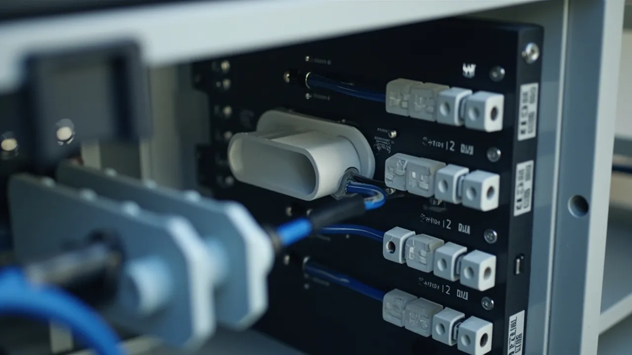
After more than a decade working with protective enclosures, the complaint I hear most often sounds like this: "The supplier said IP67, and three months after installation there was water inside." Open the box and nothing looks obviously wrong. The shell is not cracked, the gasket is not torn, none of the screws have backed off. But the sealing face has bowed upward in the middle of the span between two latches, and that is where the water came in. The problem is never one component. Waterproofing is a chain made of four links, and water always enters at the weakest one.
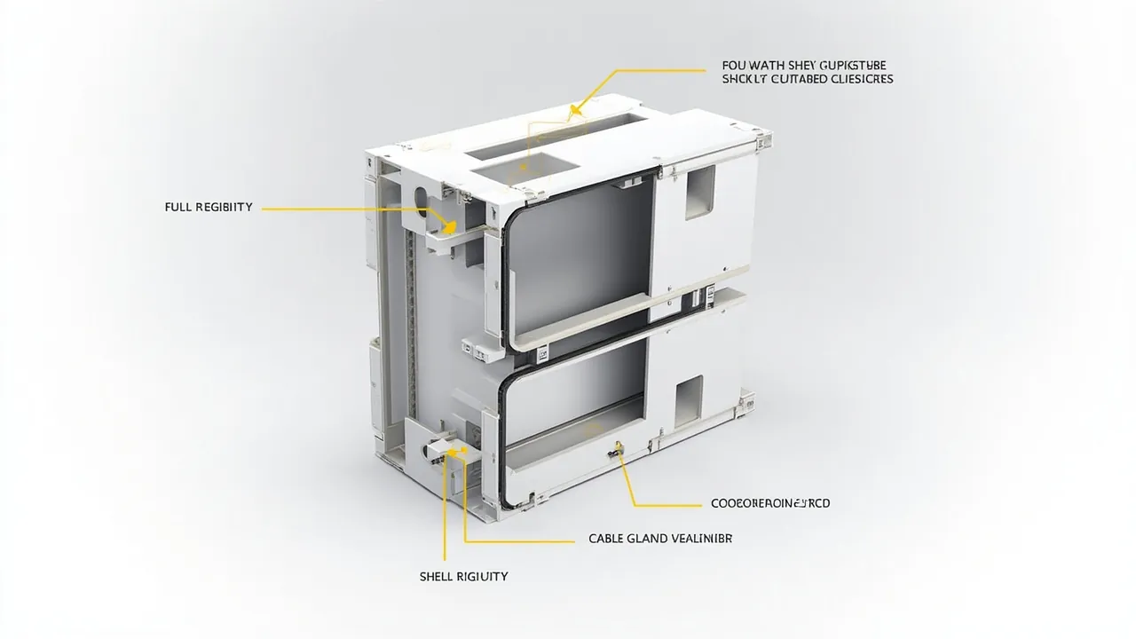
Those four links are shell stiffness, continuous perimeter sealing, clamping and latching, and cable entry. If three of them score 95 out of 100 and one scores 90, the real-world performance of the assembly is 90. Worse, the four interact: insufficient shell stiffness makes the clamping force uneven, uneven clamping makes gasket compression high on one side and low on the other, and the low side becomes the leak path. If the cable entries are handled badly, everything upstream is wasted effort.
This article takes the four links apart one by one: what physical quantity each one controls, what the numbers should be, what cost-cutting looks like in practice, and how to judge a design on a loading dock with no laboratory in sight. Test methods follow IEC 60529 (the national equivalent is GB/T 4208); material and design figures are general industry practice, so always defer to the manufacturer datasheet for a specific product.
Contents
- Waterproofing Is a System Property, Not a Part Property
- Element One: Shell Stiffness - The Sealing Face Must Not Deflect
- Element Two: Continuous Sealing - Balancing Compression and Rebound
- Element Three: Clamping and Latching - Spreading Force Around the Perimeter
- Element Four: Cable Entry - The Weakest Link Nobody Checks
- Consolidated Quantitative Checklist
- How Material and Process Affect All Four Elements
- Five Rounds of Validation From Design to Production
- Four Classic Failure Patterns and Their Root Causes
- Judging a Design at the Purchasing Stage
- Installation and Maintenance Re-Inspection
- Frequently Asked Questions (FAQ)
- Closing Thoughts and Further Reading
Waterproofing Is a System Property, Not a Part Property
Start with a fact that is easy to overlook: IP67 is awarded to an enclosure as a complete assembly, not to a gasket, a latch, or a sheet of plastic. The test object in IEC 60529 is the finished sample in the condition specified by the manufacturer, including the lid, every fastener, and every cable entry device. That means a report covering only the lid-to-body joint says nothing about the same box once four cables have been gland through it.
This is exactly why "certified on paper, leaking in the field" happens so often, and the causes fall into three groups. The first and most common: the report was produced on a bare box with unused entries sealed by factory plugs, while the field installation has four cables running through glands rated only to IP54, which drags the whole assembly down to IP54. The second is assembly variation: the report sample was tightened with a torque driver at 1.2 N·m, while the installer tightened by hand "until it felt right," delivering roughly half the design clamping force. The third is time: the report was made on a brand-new sample, while the box in the field has spent three years under ultraviolet exposure and thermal cycling that has eaten away half the gasket rebound.
Put those three together and the conclusion is plain: IP67 is not a label you buy, it is a system capability that has to be designed, assembled, and maintained. Let us take it apart.
Element One: Shell Stiffness - The Sealing Face Must Not Deflect
Sealing works by holding two faces together under clamping force. If one of those faces bends first, contact is lost, and no gasket in the world can fix that. So the first element is not the gasket at all - it is making the surface behind the gasket stiff enough.
Three stiffness quantities matter in practice. The first is the bending stiffness of the flange, the rim that carries the sealing face. Model the flange roughly as a beam under distributed load: the latches are supports, the gasket rebound is the load, and the midpoint between supports is where deflection peaks. Deflection scales with the fourth power of span - and that sentence is the single most important line in this article. Increase latch spacing from 100 mm to 200 mm and midpoint deflection becomes sixteen times larger. Products that save two latches to cut cost have multiplied the probability of seal failure by an order of magnitude.
The second is overall lid stiffness. Large lids - anything over about 400 mm on the diagonal - tend to dish under latch load, tight at the corners and bulging in the middle. Adding more latches does not solve this; only structure does: ribs, flanges, or an embedded metal frame. A workable rule of thumb is rib height two to three times wall thickness, rib spacing no more than eight times wall thickness, and ribs aligned with latch positions so the load path is continuous.
The third is sidewall resistance to external pressure, which shows up directly in the IPX7 immersion test at one metre for thirty minutes. One metre of water is about 9.8 kPa; on a 300 mm by 400 mm sidewall that is roughly 1.2 kN of total force, comparable to a small child standing on the lid. Without reinforcement the wall bows inward and pulls the sealing face open. This is why an identical gasket and latch package passes IP67 on a small box and fails on a 600 mm one.
In numbers, a defensible target is sealing face deflection of no more than 0.2 mm under rated clamping force. For low-durometer foamed gaskets you can relax that to 0.3 mm, provided the compression design has enough reserve. Both are cheap to check: feeler gauges plus a dial indicator on a sample, or finite element analysis during tool design.
Material drives stiffness through elastic modulus, and modulus is strongly temperature dependent:
| Material | Modulus at room temperature (GPa) | Modulus retention at 80 C | Design note |
|---|---|---|---|
| --- | --- | --- | --- |
| ABS | 2.0-2.6 | about 55% | Stiffness from wall and ribs; derate for heat |
| PC | 2.2-2.4 | about 70% | Tough but notch sensitive; use metal inserts at screw bosses |
| PC/ABS blend | 2.2-2.6 | about 60% | Balanced; mainstream choice for outdoor enclosures |
| Glass-filled PA/PP | 4.0-8.0 | about 65% | High stiffness but anisotropic; align flow with load |
| Die-cast aluminium (ADC12) | about 70 | about 95% | Excellent stiffness; weight and cost are the price |
| 304 stainless steel | about 193 | about 95% | Best stiffness; severe corrosion or impact duty |
One warning worth repeating: plastics lose modulus fast as temperature rises. A dark enclosure bolted to a metal pole at midday in summer can reach 70 to 80 C surface temperature, at which point ABS retains a little over half its room-temperature modulus and deflection under the same clamping force roughly doubles. Either change material for hot climates or recalculate clamping force and latch spacing using the hot modulus.
Element Two: Continuous Sealing - Balancing Compression and Rebound
With a stiff face in place, the gasket can do its job. Note what that job actually is: not "blocking water," but maintaining a continuous, gap-free, long-term stable contact band across the sealing face.
Three parameters have to be satisfied simultaneously.
Compression ratio. The proportion by which the gasket is squeezed, normally designed between 25% and 35%. Below 20%, contact stress is too low to fill the microscopic roughness of the sealing face - injection-moulded surfaces run Ra 0.8 to 3.2 micrometres, die-cast surfaces can be rougher - and water creeps through the remaining channels. Above 40%, internal stress in the rubber accelerates compression set, pushes the lid off its seat, and overloads the latches, so the design fails sooner than a correctly compressed one.
Compression set. This is the measure of whether a gasket springs back after long compression, tested to ASTM D395 or GB/T 7759, commonly at 70 C for 22 hours or 100 C for 70 hours. A serviceable outdoor seal should show no more than 25% set under 70 C for 22 hours; good silicone compounds reach under 15%. This figure sets the maintenance interval directly: 30% set means only seventy percent of rebound remains after a few years, and if the original compression ratio was just 25%, contact stress may already be below the leakage threshold.
Groove fill ratio. Compressed rubber has to go somewhere, so the groove cross-section must exceed the gasket cross-section - but not by too much. Fill ratio, gasket area divided by groove area, is normally held between 70% and 85%. Too low and the gasket rattles loose in the groove; above 90% the rubber has nowhere to go and jacks the lid open, creating the bulged-centre failure mode along with a sharp rise in latch load.
Four seal families dominate outdoor enclosures, each with its place:
| Seal material | Hardness (Shore A) | Service temperature | Compression set | Where it fits |
|---|---|---|---|---|
| --- | --- | --- | --- | --- |
| Solid silicone (VMQ) | 40-60 | -55 to 200 C | Excellent (under 15%) | Wide temperature range and weathering; higher cost, modest tear strength |
| Foamed EPDM | 15-35 (foam) | -40 to 120 C | Moderate (20-35%) | Low closing force, conforms to rough faces; poor oil resistance, low tear strength |
| Solid EPDM | 50-70 | -40 to 120 C | Good (15-25%) | Weather and ozone resistant, best value; the most common choice |
| TPE / TPV | 40-70 | -40 to 120 C | Moderate (25-40%) | Co-extrudable, low cost; weaker long-term high-temperature behaviour |
One more detail: corners. The four right angles of a rectangular enclosure are where leaks start, because the gasket is either stretched or bunched at the corner. Mature tooling uses a continuously vulcanised ring with moulded corners instead of four butt-joined straight lengths, or keeps the corner radius at least 1.5 times the gasket cross-section width. In the field, look for a visible joint line, lift, or chewed section at the corners - that is the fingerprint of the cheap solution.
Element Three: Clamping and Latching - Spreading Force Around the Perimeter
A gasket only works if it is compressed evenly, and even compression comes from the latches. The job of a latch is to generate adequate, evenly distributed contact stress around the whole perimeter - not merely to hold the lid shut.
How much force is needed? Take a 1200 mm perimeter with a 6 mm diameter solid EPDM cord at 30% compression: the required line load is roughly 1.5 to 3 N per millimetre, depending on hardness and profile. Total clamping force lands between 1800 and 3600 N, the equivalent of 180 to 360 kilograms-force. That number tells you something important: four small screws cannot do this job, which is why serious products use wide, thick latches with obvious lever geometry.
Distribution matters just as much. The rule is equal spacing, symmetric layout, and tighter spacing near corners. Practical values: adjacent latch spacing not more than 120 mm, and at least one latch within 80 mm of every corner. A 400 mm by 300 mm enclosure therefore needs at least four latches on the long side and three on the short side, and corner reinforcement usually brings the total to six to eight. Products that exceed the spacing limit always have an under-compressed band at mid-span, and a 0.05 mm feeler gauge will slide right in - a genuinely useful field test.
Latch types differ more than buyers expect:
- Over-centre cam latches. An eccentric cam passes dead centre and locks, giving high and stable clamping force. The mainstream choice for outdoor enclosures. Good versions add a secondary catch against accidental opening, with 304 stainless hardware.
- Bolted compression. The most controllable option, since torque can be quantified, but slow to open. Best where the box is rarely opened. Torque belongs on the nameplate or in the manual: typically 1.0 to 1.5 N·m for M4, 2.0 to 3.0 N·m for M5.
- Snap-fit. Fastest to operate, but clamping force is limited and decays quickly as the plastic creeps. Generally seen only indoors or on low-rated enclosures.
- Hinge-side compression. Many designs put every latch on the opening side and rely on the hinge to compress the back edge, which is a classic flaw. The hinge side needs its own compression points, or the hinge should be built with a compression ramp.
Plastic creep is the quiet enemy in this element. A moulded latch under continuous load creeps and loses force over time. In a loaded heat-ageing test at 70 C for 1000 hours, a poor latch can shed more than 30% of its clamping force. For applications that must run unattended for years, prefer metal latches or metal-reinforced designs.
Element Four: Cable Entry - The Weakest Link Nobody Checks
If only one thing in this article sticks, let it be this: in the great majority of "IP67 box leaked" cases, water came in through the cables, not through the lid.
The reason is straightforward. The lid-to-body seal is designed, validated, and mass-produced under controlled factory conditions. Cable entry is done on site with a utility knife, a drill, and a roll of PTFE tape. A manufacturer owns the quality of the first; a contractor's mood owns the quality of the second.
Correct cable entry has to satisfy four conditions at once.
First, the entry device must be rated at least as high as the enclosure. Cable glands carry their own IP rating, commonly IP68 with depth and duration stated, for example "IP68, 2 m for 24 h". An IP67 box fitted with IP54 glands is an IP54 assembly. Treat glands as a separately specified item with their own report.
Second, the clamping range must match the cable. Every gland states a range, for example "M20, cable diameter 6-12 mm". Clamping a 4 mm cable in an M20 gland leaves the seal unable to grip, which is no seal at all. Forcing a 14 mm cable in overstretches the rubber until it cracks. This is the single most frequent site error.
Third, entries should face downward. All outdoor entries belong on the bottom of the enclosure, with a drip loop inside - the cable runs down before it turns up to the terminals. Gravity keeps water away from a downward-facing entry; an upward or side-facing entry becomes a funnel the moment the seal ages.
Fourth, spare openings must be sealed. Unused knockouts need plugs rated to the same level as the enclosure. Tape, sealant, or "it faces down so it should be fine" are not acceptable. One open knockout drops an IP67 enclosure to roughly IP20.
There is also an advanced issue: breathing and condensation. A perfectly sealed enclosure breathes as day and night temperatures swing, drawing in humid air that condenses on cold walls. This sits slightly outside the four elements and is normally handled with a vent - a waterproof membrane such as expanded PTFE, passing tens to hundreds of mL per minute per square centimetre at 7 kPa while still holding IP67 or IP68 - or with desiccant. Fitting a vent does not compromise the IPX7 test, because the membrane blocks liquid water.
Consolidated Quantitative Checklist
Compressed into something you can actually use:
| Element | Controlled quantity | Recommended target | Rough field check |
|---|---|---|---|
| --- | --- | --- | --- |
| Shell stiffness | Sealing face deflection | 0.2 mm or less at rated clamp load | No visible twist under diagonal load; wall at least 2.5 mm with ribs |
| Shell stiffness | Latch span | 120 mm or less, point within 80 mm of corner | Count latches; perimeter divided by latch count is 120 or less |
| Sealing | Compression ratio | 25% to 35% | Even joint line; 0.05 mm feeler gauge will not enter |
| Sealing | Compression set | 25% or less at 70 C for 22 h | Ask for a third-party report |
| Sealing | Groove fill | 70% to 85% | Gasket removable intact, no extrusion damage |
| Latching | Total clamp load | 1.5 to 3 N per mm of seal | Firm closing force with a distinct final click |
| Latching | Bolt torque | M4 1.0-1.5 N·m; M5 2.0-3.0 N·m | Sample check with a torque driver |
| Cable entry | Gland rating | Equal to or above enclosure rating | Ask for the gland's own report |
| Cable entry | Clamp range match | Cable OD inside stated range | Measure cable on site and compare |
| Cable entry | Entry direction | Bottom entry plus drip loop | Visual |
| Cable entry | Spare openings | Plugged to the same rating | Visual |
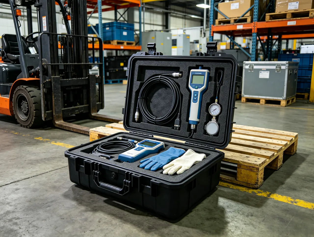
This table works directly as a goods-in inspection sheet, or as a technical annex when you negotiate with a supplier.
How Material and Process Affect All Four Elements
The four elements are not independent; material choice touches all of them at once.
| Approach | Stiffness | Sealing method | Clamping method | Entry handling | Overall |
|---|---|---|---|---|---|
| --- | --- | --- | --- | --- | --- |
| Injection-moulded ABS | Moderate, derates in heat | Separate gasket or moulded lip | Plastic latch, watch creep | Drill for glands | Low cost, light; light duty and sheltered outdoor use |
| Injection-moulded PC/ABS | Moderate to good, tough | Separate gasket | Plastic or metal latch | Drill for glands | Best balance; mainstream outdoor low-voltage choice |
| Glass-filled PP/PA | High, anisotropic | Separate gasket | Metal latch preferred | Drill for glands | Strong, corrosion resistant; mind flow direction |
| Die-cast aluminium | Very high | Gasket, machined sealing face | Bolted, torque controlled | Drill; watch galvanic corrosion | Best strength and heat dissipation; heavy, needs finishing |
| 304/316 stainless steel | Very high | Gasket or conductive gasket | Bolted, torque controlled | Drill for glands | Severe corrosion, food and pharma; highest cost |
| Compression-moulded SMC/GRP | High | Gasket | Metal latch | Drill for glands | Good insulation and corrosion resistance; power and telecom |
Two process details are routinely ignored. Weld line placement: a weld line in an injection moulding carries only 60% to 80% of base material strength, so a weld line running along the sealing face can crack under sustained load. Draft and parting-line flash: if the parting line falls on the sealing face, flash lifts the gasket and opens a channel. Good tooling keeps both away from the sealing zone, and that needs to be settled with the toolmaker during sampling.
Five Rounds of Validation From Design to Production
A dependable IP67 rating is not produced by a single test; it is built through successive rounds.
Round one, component level. Gaskets: compression set, hot-air ageing (70 C for 168 h, or per GB/T 3512), low-temperature brittleness. Latches: cycle life, 500 to 2000 open-close cycles, plus pull-to-failure. Sheet material: tensile, impact, heat deflection temperature. This round sets the floor for every incoming part.
Round two, structural level. Complete units for IP5X/IP6X dust testing - a first digit of 6 under IEC 60529 means eight hours of talcum powder under reduced pressure - and IPX7 immersion at one metre for thirty minutes with a temperature difference not exceeding 5 kelvin. Samples must be in the manufacturer's declared service condition: real glands, real plugs, tightened to declared torque.
Round three, environmental ageing then retest. Thermal cycling, for example minus 30 C to 70 C for 20 to 50 cycles; ultraviolet exposure per GB/T 16422.2 fluorescent lamp for 500 to 1000 hours; neutral salt spray per GB/T 10125 for 480 to 1000 hours on metals and coatings. Then repeat IPX7. This round eliminates solutions that pass new and leak after a year.
Round four, tooling consistency. A pilot run of 20 to 50 units, each leak-tested by pressure decay - a common criterion is no more than 10% to 20% loss from 5 kPa in thirty seconds - to assess process capability. This round eliminates designs that work in the lab but cannot be built.
Round five, field follow-up. Inspect the first projects at three, six, and twelve months: sealing faces, torque, condensation. Problems found in real service are usually worth more than anything found in the lab.
Skip any round and you are trading project risk for schedule.
Four Classic Failure Patterns and Their Root Causes
Pattern one, mid-span seepage. Water enters along the middle of a run while the ends stay dry. The cause is almost always excessive latch spacing or insufficient lid stiffness, so mid-span deflection exceeds what the gasket can absorb. Fix it with more latches or more ribs; do not reach for extra sealant.
Pattern two, corner seepage. The corners go first. Causes are gasket bunching and nibbling at corners, or latch points too far from the corner. Fix it with a one-piece vulcanised gasket ring and closer corner latches.
Pattern three, tracking along cables. The interior is dry except for dampness at the bottom of the terminal block, with water running down the cable sheath. Causes are mismatched gland clamping range, inadequate tightening, or out-of-round cable - cheap cable is sometimes visibly oval. Fix it with correctly sized glands, torque-controlled tightening, and if necessary a separate waterproof jointing enclosure.
Pattern four, internal condensation. The seal is intact but the walls are beaded with water. This is not ingress; it is humid air breathed in and condensed on cold walls. Diagnose by distribution: condensation spreads evenly across walls and lid, while ingress pools at the bottom and leaves tidemarks. The remedies are entirely different - a vent to equalise pressure, desiccant, smaller internal air volume, and layout that avoids local cold spots. Thickening the gasket does nothing.
These four need completely different fixes, which is why site diagnosis should follow a fixed order: condensation first, cables second, lid seal last.
Judging a Design at the Purchasing Stage
Without any paperwork, a five-minute physical inspection gets you a long way.
Count and position the latches. Measure the perimeter, count the latches, and deduct points for spacing over 120 mm. Deduct more if the opening side has latches and the hinge side has none.
Measure the sealing face and gasket. A face narrower than 6 mm or a cord under 3 mm in diameter suggests thin margins on both performance and life. The gasket should come out in one piece - foamed types excepted - and rebound visibly; press with a fingernail and it should recover within a second.
Check wall thickness and ribs. Use callipers on the sidewall and flange; treat injection-moulded walls under 2.5 mm with caution. Look inside the lid for ribs and judge whether rib height is sensible relative to wall thickness.
Inspect the entry area. Are there knockouts on the bottom, matching glands and plugs, and are the plugs rated like the enclosure? A product shipped without plugs will almost certainly be sealed with improvised methods on site.
Look at the metal hardware. Outdoor stainless fittings should be at least 304. Ordinary zinc-plated screws will be seized solid within a year.
When you ask for the report, be specific on three points: whether the sample included glands and the real configuration; whether the model number matches what you are buying; and whether the issuing laboratory holds CNAS, CMA, or ILAC mutual recognition accreditation. Those three answers matter more than the word "pass" on the cover.
Installation and Maintenance Re-Inspection
Good design still needs good installation. A workable checklist:
At installation: bottom entry, drip loops, glands tightened to torque - typically 4 to 6 N·m for M20 and 6 to 9 N·m for M25, subject to the manufacturer's data - bolts tightened diagonally in stages of 50%, 80%, and 100% across two or three passes, spare openings plugged, desiccant and a humidity indicator card fitted inside.
Before energising: a simple leak or spray check, and a record of the date and torque values.
During service: re-torque every six to twelve months, especially after the first hot summer; inspect the gasket for permanent indentation, cracks, or set every time the box is opened; replace desiccant the moment the indicator changes colour and check the seal at the same time; inspect and clean after flooding, heavy rain, or a typhoon.
Replacement intervals: solid EPDM typically lasts five to eight years in ordinary outdoor service, silicone eight to ten, foamed sections only three to five. High temperature, strong ultraviolet, or coastal salt spray shorten all of those by 30% to 50%.
Frequently Asked Questions (FAQ)
Q: Is IP67 a rating for the gasket or for the enclosure? A: For the complete enclosure. The test object in IEC 60529 is the assembled unit in the manufacturer's declared condition, including the lid, all fasteners, and all entry devices. Saying "this gasket is IP67" is meaningless; a gasket has material properties such as compression set, hardness, and temperature range instead. When you buy, ask for a whole-unit report and confirm the sample carried the same glands, plugs, and vents as your order, because otherwise the report and the product are two different things. That mismatch is one of the most common roots of "certified on paper, leaking in the field".
Q: What latch spacing should I actually use, and can I get away with only four? A: Aim for no more than 120 mm between adjacent latches and at least one compression point within 80 mm of each corner. Four latches are fine on a 200 mm box and not fine on anything over about 400 mm by 300 mm, because beam deflection scales with the fourth power of span: double the spacing and deflection grows sixteen fold, far beyond what gasket compression reserve can absorb. On site, run a 0.05 mm feeler gauge around the joint; anywhere it slides in is under-compressed, and that is more trustworthy than any verbal assurance.
Q: Is a higher gasket compression ratio always better? A: No. The working range is 25% to 35%. Below 20%, contact stress cannot fill the micro-roughness of the sealing face and water creeps along the remaining channels. Above 40%, internal stress accelerates compression set, the gasket jacks the lid into a bulged-centre failure, and latch load rises sharply enough to overload the hardware. The safer engineering choice is a mid-range 30% compression with groove fill held at 70% to 85%, leaving room for the rubber to deform. That protects both the initial seal and the ageing margin.
Q: The seal looks perfect, so why is there water beading inside? A: That is almost certainly condensation rather than ingress. A fully sealed enclosure breathes as temperatures swing: air expands and escapes during the day, then contracts at night and draws moist outside air back in, and the moisture condenses on cold internal walls. Check the distribution to tell them apart - condensation coats walls and the underside of the lid evenly, while ingress pools at the bottom and leaves tidemarks along its path. The fixes are also different: fit a waterproof vent to equalise pressure, add desiccant, reduce internal air volume, and avoid local cold spots. Fitting a thicker gasket achieves nothing here.
Q: Do cable glands need their own ingress rating certification? A: Yes. A gland is a separate component with its own IP rating, and it is usually the weakest link in the whole assembly. The usual requirement is a gland rating at least equal to the enclosure, so an IP67 box takes IP68 glands with depth and duration stated. Watch three things when buying: ask for the gland's own test report; check that the clamping range matches the cable diameter, because clamping a 4 mm cable in an M20 gland is no seal at all; and confirm that the gland material will not galvanically corrode against the enclosure, since a plain nickel-plated brass gland in an aluminium box corrodes quickly in salt spray.
Q: Which reaches IP67 more easily, a metal or a plastic enclosure? A: Each wins in different territory, decided by size and duty. Metal - die-cast aluminium or stainless - is stiff, allows a machined sealing face, and permits quantified bolt torque, so it holds up better on large sizes and high pressure differentials; the price is weight, cost, galvanic corrosion, and surface finishing. Plastic is light, insulating, corrosion resistant, and cheap, but its modulus drops sharply with heat - ABS retains only about 55% at 80 C - so large or hot applications need ribs and closer latch spacing to compensate. As a rough guide, engineering plastic gives better value for outdoor low-voltage enclosures under 400 mm, while metal is the safer answer for larger sizes, heavy impact, or aggressive corrosion.
Q: How do I quickly tell whether a supplier's IP67 claim is real? A: Four steps. First, read the sample description: does it state the model, does it include glands and other entry devices, and does it record orientation and tightening torque? Second, check the laboratory: is there a CNAS, CMA, or ILAC mutual recognition mark, and can the report number be verified through the issuing body? Third, read the test conditions: IPX7 should state one metre, thirty minutes, and a temperature difference not exceeding 5 kelvin, and any report that merely says "complies with IP67" without numbers deserves suspicion. Fourth, sample the physical product: feeler gauge around the joint, count latch spacing, measure the gasket. Documents first, hardware second, and only agreement between them counts as credible.
Q: An enclosure is already installed and the seal is poor. Can it be rescued? A: Yes, in tiers, with limited upside. Light problems - insufficient clamping - respond to re-torquing bolts and adding latches, cheap and effective. Medium problems - aged gasket or excessive compression set - call for a replacement gasket of the same specification, with the sealing face cleaned, old residue removed, and the original compression ratio maintained. Severe problems - distorted shell, excessive latch spacing, badly made entries - cannot be cured on site and the unit should be replaced. One thing to avoid: smearing sealant or silicone along the joint. It stops water briefly, then bonds the gasket to the face so the next opening destroys the sealing surface, and its weather resistance usually fails within a year or two.
Closing Thoughts and Further Reading
Back to the complaint at the top. Whether an outdoor low-voltage enclosure holds IP67 over the long run depends on all four elements standing up together: shell stiffness keeps the sealing face flat, continuous sealing maintains an unbroken contact band, clamping and latching keep force even and durable, and cable entry stops the weakest link from dragging everything down. The weakest of the four sets the real capability of the box.
If you want three lines to take away, they are these: fix the two numbers of latch spacing and compression ratio during design; insist on a whole-unit report that includes glands, and check the laboratory's accreditation; and make bottom entry, torque-controlled tightening, and periodic re-inspection a written routine. Do those three and the great majority of water ingress problems never appear.
JUNZHJIA enclosures are manufactured by Kexin New Materials (Guangdong) Co., Ltd. at its Zhongshan plant. The waterproof junction box and electrical enclosure lines cover IP65 through IP68, with shell stiffness, sealing system, clamping structure, and entry scheme engineered as one system. Third-party reports, whole-unit immersion records, and OEM/ODM customisation are available, with wholesale supply worldwide.
Further reading