

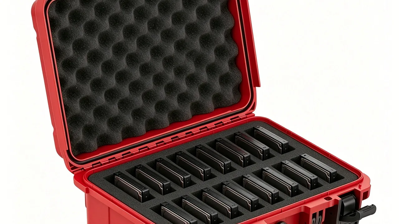
A case holding an underwater camera slides off an inflatable boat and sinks into two metres of muddy water. Twenty minutes later it is recovered, and when the lid opens the interior must be completely dry. Whether that happens does not depend on how solid the case looks; it depends on whether compression along the sealing line is uniform, how much rebound the gasket retains after long service, and whether pressure difference will draw water in. Waterproof case design is essentially the work of turning a vague goal, keeping water out, into four calculable engineering problems: seal face geometry, compression force distribution, material rebound and pressure management.
JUNZHIJIA's position on waterproof protective cases is this: waterproofing is not simply clamping a lid down, it is making seal groove geometry, gasket compression ratio, compression point spacing and pressure equalisation all hold simultaneously, and keeping them holding after long term ageing. Everything below follows from that statement, ending in selection tables and test criteria that can be applied directly.
Table of Contents
- Immersion Ratings: How IPX7 and IPX7 Test Conditions Actually Differ
- The First Element: Seal Groove Geometry and Compression Ratio
- Gasket Material Selection: Compression Set of Silicone, EPDM and TPE
- Where Compression Force Comes From: Latch Count, Spacing and Line Load
- Flange Stiffness and Deflection: Why a Clamped Case Still Leaks
- Pressure Equalisation Valves: Breathing, Differential Pressure and Immersion
- Secondary Seals and Feed-Throughs: Panels, Windows and Cable Entry
- Immersion Testing: Procedure Details and Common Misjudgements
- Long Term Sealing Reliability: Ageing, Thermal Cycling and Service
- Drainage, Drying and Supporting Accessories
- Selection and Acceptance Checklist: From Water Depth to Criteria
- Frequently Asked Questions FAQ
- Conclusion and Related Reading
Immersion Ratings: How IPX7 and IPX7 Test Conditions Actually Differ
The first step in waterproof work is translating "waterproof" into measurable test conditions. In IEC 60529 and GB/T 4208, the second characteristic digit separates spraying at IPX5 and IPX6 from temporary immersion at IPX7, continuous immersion at IPX8 and high pressure hot spray at IPX9. Only IPX7 and IPX8 correspond to the scenario of sinking under water.
IPX7 conditions are stated precisely. For a specimen under 850 mm tall, its lowest point sits 1000 mm below the surface; for a specimen 850 mm or taller, its highest point sits 150 mm below the surface. Duration is 30 minutes, and the temperature difference between water and specimen must not exceed 5 K. The acceptance judgement is that no water enters, or that any water entering does not impair normal operation or break safety isolation, as defined by the relevant product standard.
IPX8 conditions are not fixed by the standard. They are agreed between manufacturer and user and must be more severe than IPX7. That sentence carries three implications. First, IPX8 must exceed IPX7, so 30 minutes at one metre does not qualify. Second, the specific depth and duration must be declared on the rating plate, in documentation or in the specification, for example two metres for sixty minutes. Third, the acceptance criteria must also be agreed in advance. When quoting an IPX8 programme JUNZHIJIA asks the customer to state target depth, duration and whether salt spray or silt is involved, because those three factors change gasket and metal part selection outright.
One caveat matters more than any number: an IP rating describes performance under the test conditions, not long term reliability. A case that passes IPX7 on the day it leaves the factory may not pass it two years later. Service life is governed by gasket compression set, corrosion resistance of metal parts and creep resistance of the flange, all of which are covered below.
| Rating | Medium and Method | Key Parameters | Duration | Typical Scenario |
|---|---|---|---|---|
| --- | --- | --- | --- | --- |
| IPX5 | Nozzle spray | 6.3 mm nozzle, 12.5 L per min | 1 minute per square metre | Washdown, work in rain |
| IPX6 | Powerful spray | 12.5 mm nozzle, 100 L per min | 1 minute per square metre | Decks, heavy storm |
| IPX7 | Temporary immersion | Lowest point 1000 mm below surface | 30 minutes | Drop overboard, wading |
| IPX8 | Continuous immersion | Declared by maker, worse than IPX7 | Declared by maker | Long submersion, diving |
| IPX9 | High pressure hot spray | 80 C, 8 to 10 MPa | 30 seconds per position | Vehicle pressure washing |
The First Element: Seal Groove Geometry and Compression Ratio
The most overlooked element in a sealing structure, and the one that decides success, is the groove. Many people assume waterproofing comes from a thicker strip and a tighter lid, but what engineering can actually control are three geometric quantities: groove depth, groove width and fill ratio.
Compression ratio comes first. It is defined as the free section height minus the compressed height, divided by the free section height. For solid silicone cord the usual design band is 15 to 25 percent. Below 10 percent the microscopic unevenness of the sealing face is not filled and leakage paths remain. Above 30 percent the material enters a high stress region, compression set accelerates, long term sealing force decays noticeably and closing force rises steeply.
Groove fill ratio is the free cross sectional area of the gasket as a proportion of the groove cross sectional area, normally 70 to 90 percent. Reserving 10 to 30 percent of space is necessary because the material expands with heat and with absorbed moisture; at a fill ratio near 100 percent a temperature rise will jack the lid open or extrude the strip out of the groove. JUNZHIJIA holds fill ratio near 80 percent and adds a small vent channel at the groove bottom so trapped air cannot prevent full closure.
Groove profile depends on assembly method. A rectangular groove is easy to machine but the strip can walk outwards under pressure. A dovetail groove mechanically retains the strip and suits cases opened frequently or loaded sideways. A semicircular groove mates best with round cord but demands tighter machining. Groove edge radius should be 0.2 to 0.4 mm, because sharp corners cut the strip during assembly and act as stress raisers.
Seal face surface quality matters equally. Injection moulded seal faces should be held between Ra 0.8 and 1.6 micrometres. Rotationally moulded parts are inherently rougher, so they usually need secondary machining on the seal face or a softer, higher compression strip to compensate. Flatness along the seal line should be within 0.1 mm per 100 mm; rotomoulded parts often need a sizing fixture or local machining to achieve it.
| Parameter | Usual Value | Consequence Too Low | Consequence Too High |
|---|---|---|---|
| --- | --- | --- | --- |
| Compression ratio, silicone cord | 15 - 25 percent | Face unevenness not filled, leaks | High closing force, faster set |
| Compression ratio, EPDM | 20 - 30 percent | Same as above | Same as above |
| Groove fill ratio | 70 - 90 percent | Loose strip, walks out | Lid jacked open, extrusion |
| Groove edge radius | R0.2 - R0.4 | Cuts the strip, stress raiser | Insufficient seal line width |
| Seal face roughness | Ra 0.8 - 1.6 micrometres | - | Needs softer strip |
| Seal face flatness | 0.1 mm per 100 mm | - | Uneven compression |
Gasket Material Selection: Compression Set of Silicone, EPDM and TPE
Among gasket material indicators, the most important is not hardness but compression set. It describes how much rebound capacity the material loses after prolonged compression, measured to ASTM D395 method B or GB/T 7759: compress the specimen to a defined deflection, normally 25 percent, hold it at a defined temperature for a defined time, typically 22 hours at 70 C or 70 hours at 100 C, release and measure thickness recovery. Lower is better.
Silicone, or VMQ, is the mainstream choice for waterproof case seals. Its temperature range is wide, commonly covering minus 55 to 200 C, it stays elastic at low temperature, compression set falls between 10 and 20 percent, weathering and ozone resistance are excellent and it is physiologically inert, which suits medical and food related uses. Its weaknesses are modest tear strength, average abrasion resistance and sensitivity to some oils and solvents; a solid silicone strip nicked by a sharp edge during assembly can tear along that nick in service.
EPDM offers good mechanical strength, abrasion resistance and weathering, with compression set between 15 and 25 percent, at a lower price than silicone, plus excellent resistance to steam and to acids and alkalis. Its fatal weakness is poor oil resistance: contact with mineral oils and greases causes swelling and failure, so it must be used with care in industrial environments where oil is present. Low temperature behaviour depends on formulation, with general purpose grades stiffening around minus 40 C.
TPE can be extruded or injection moulded like a plastic, giving high processing efficiency and recyclability, and it can be moulded integrally with the case body in a two-shot soft-hard construction. That is its main advantage in volume waterproof products. Its drawback is compression set typically between 30 and 50 percent, clearly worse than silicone or EPDM and worse still at high temperature. TPE integral seals therefore suit consumer or light industrial products where structure and seal are one, and need careful evaluation before use in high reliability IPX8 service.
| Material | Hardness Shore A | Compression Set | Temp Range (C) | Weather and Ozone | Oil Resistance | Main Use |
|---|---|---|---|---|---|---|
| --- | --- | --- | --- | --- | --- | --- |
| Silicone VMQ | 40 - 70 | 10 - 20 percent | -55 to 200 | Excellent | Fair | Mainstream IPX7 and IPX8 |
| EPDM | 50 - 75 | 15 - 25 percent | -40 to 130 | Excellent | Poor | Outdoor waterproofing, steam |
| TPE | 40 - 80 | 30 - 50 percent | -30 to 100 | Good | Fair | Integral lightweight sealing |
| Neoprene CR | 50 - 70 | 20 - 30 percent | -30 to 110 | Good | Good | General industrial |
| FKM fluoroelastomer | 60 - 80 | 15 - 25 percent | -20 to 200 | Excellent | Excellent | High temperature oily service |
| NBR nitrile | 50 - 80 | 20 - 35 percent | -30 to 110 | Poor | Excellent | Oily service, poor weathering |
Where Compression Force Comes From: Latch Count, Spacing and Line Load
Compressing a gasket to its design ratio requires continuous force along the entire seal line. That force is supplied by latches, and latches are discrete points, so the core design question becomes how many points at what spacing will keep pressure on the seal line sufficiently uniform under discrete loading.
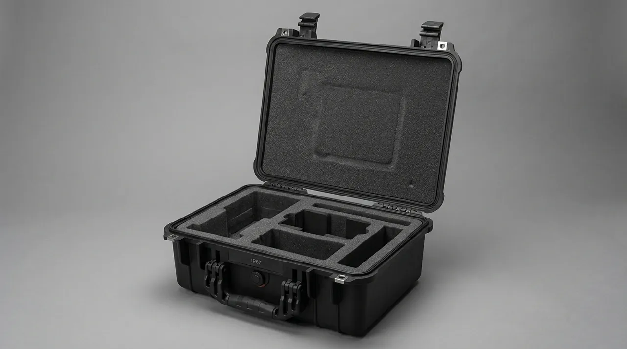
Engineers describe the requirement as a line load, the compression force needed per millimetre of seal line, in newtons per millimetre. Solid silicone cord at 20 percent compression typically needs 1 to 3 N per mm depending on cord diameter and hardness. A 400 mm seal line at 2 N per mm needs about 800 N in total; shared across four latches that is roughly 200 N each, which is a demanding figure for a plastic over-centre latch.
The empirical rule for latch spacing is no more than 120 to 150 mm, with closer spacing or a continuous compression bar at corners. The reason is that the midpoint between two latches receives the least compression, and excessive spacing can push the local ratio below 10 percent, creating a leak path. Corners experience the largest geometric distortion and transmit compression least effectively, so they are a classic failure location; JUNZHIJIA uses twin latches or an extended corner compression block there.
Transmission of compression force also depends on lid stiffness. If the lid bends between two latches, force never reaches the midpoint and the effective ratio falls below the calculated one. Latch count, spacing and lid stiffness must therefore be designed together: thicker lids, ribs along the seal line and metal compression frames are the common answers. Adding latches without increasing lid stiffness gives sharply diminishing returns.
Opening force is the constraint at the other end. More compression means harder opening and worse user experience. The sensible approach is to decouple holding force from opening force mechanically, for example with an over-centre cam latch that delivers high compression once past centre and unloads before release. JUNZHIJIA recommends over-centre latches on frequently opened waterproof cases and asks that opening force stay within an acceptable 30 to 80 N band.
| Seal Line Length | Line Load (N/mm) | Total Force Needed (N) | Suggested Latches | Force per Latch (N) |
|---|---|---|---|---|
| --- | --- | --- | --- | --- |
| 300 mm | 2.0 | 600 | 3 | 200 |
| 400 mm | 2.0 | 800 | 4 | 200 |
| 600 mm | 2.5 | 1500 | 5 | 300 |
| 800 mm | 2.5 | 2000 | 6 | 333 |
Flange Stiffness and Deflection: Why a Clamped Case Still Leaks
When latches are fully engaged and water still gets in, the usual root cause is not insufficient force but flange deflection. Body and lid form a flange pair at the seal line, and inadequate stiffness in either half produces warping or local collapse under compression, so that some sections of the seal line end up below their designed compression.
Flange deflection has three sources. The first is structural: the flange bends between latch points and lifts at the midpoint; corners twist because the two flanges are not coplanar. The second is processing: shrinkage warpage in injection moulding, uneven wall thickness and cooling distortion in rotational moulding all push flange flatness out of tolerance. The third is long term: plastics creep under sustained load, the flange gradually takes a permanent set and compression force falls with time.
Control measures ranked by effectiveness are: increasing flange thickness and adding ribs, which is the most effective; reducing latch spacing to spread concentrated load; fitting a metal compression frame or inserts to convert point loads into line loads; optimising gate position and cooling to reduce moulded warpage; and selecting a more creep resistant material such as glass filled PP. On large waterproof cases JUNZHIJIA uses a composite of a plastic flange plus an aluminium extrusion compression frame, so the frame spreads latch load along the whole seal line and the flange only carries a distributed load.
Deflection can be quantified by measuring compression distribution along the seal line. In practice, pressure indicating film or lead wire is laid on the seal, the case is closed, and the width and thickness of each compression mark is measured, requiring no point around the perimeter to fall below 70 percent of design compression. A more precise approach is finite element analysis under combined latch load and pressure differential, extracting compression point by point for verification.
Internal pressure also deflects the flange. With a pressure difference between inside and out, caused by altitude, air freight or rapid temperature change, the flange is pushed outwards: at 10 kPa, a lid face of 300 by 200 mm carries roughly 600 N of resultant force, enough to pull the seal line open. That is the main reason a pressure equalisation valve exists.
Pressure Equalisation Valves: Breathing, Differential Pressure and Immersion
The most counter-intuitive fact about waterproof cases is that a perfectly sealed case is more likely to be damaged, or to take water. The cause is differential pressure. A case sealed at 25 C at ground level, then carried to 3000 metres or loaded into an unpressurised cargo hold, sees external pressure fall to about 70 kPa while the interior stays near 100 kPa. The resulting 30 kPa acts on the lid, potentially bowing it, pulling the seal line open, or releasing a dangerous high speed vent when the case is opened.
A pressure equalisation valve, also called a breather or vent, solves this with a microporous membrane, usually expanded PTFE with pore sizes between 0.1 and 5 micrometres. The principle is direct: the pores are far smaller than water droplets, which are above 100 micrometres even in fine mist and above 20 micrometres in fog, yet far larger than the mean free path of gas molecules, so gas passes while liquid water cannot. Just as important, the membrane has extremely low surface energy, so water cannot wet and spread across it and the contact angle stays high.
Two parameters define performance: air flow and water entry pressure. Air flow is quoted as volumetric flow at a stated differential, for example millilitres per minute at 7 kPa. Water entry pressure, or WEP, is the pressure at which the membrane starts to pass water; standard products are specified at no less than 30 kPa and good ones exceed 100 kPa. One metre of water, the IPX7 condition, corresponds to about 9.8 kPa of static pressure and five metres to about 49 kPa, so selection must give a WEP greater than the target static head with a two to three times margin.
Installation position matters too. The valve should sit on the lid where it is least exposed to direct impact, with an internal guard so contents cannot press against the membrane, and if liquids may be carried it should face upwards or carry a splash shield. The joint between valve body and case is itself a seal, normally a threaded O-ring fitting or an ultrasonic weld, and must be tightened to the specified torque. JUNZHIJIA specifies at least one valve per waterproof case, and two mounted diagonally where volume exceeds 50 litres or air freight is routine.
To be clear, a valve does not replace sealing design; it only manages differential pressure. It also means that during immersion the interior is gas-connected to the outside, so if the membrane is damaged or specified without margin, water enters straight through the valve. Valves therefore belong on the periodic replacement list and must be verified during immersion testing. More background is available in Pressure Equalisation Valves for Cases.
Secondary Seals and Feed-Throughs: Panels, Windows and Cable Entry
The weakest point of a waterproof case is usually not the main seal line but the places that must be opened up: connector panels, buttons, viewing windows, cable exits and antenna ports. What these share is a small sealing face, complex geometry and, frequently, an operating load to carry.
For panel feed-throughs the principle is independent sealing plus mechanical fixing. A panel must have its own gasket and must not rely on the main seal line to press it as a side effect. Fixing screws should be distributed outside that gasket at no more than 80 mm spacing, with sealing washers or thread sealant. If the panel carries buttons, prefer a one-piece silicone keypad membrane, or metal buttons with O-ring shaft seals.
Cable entry should use a standard waterproof cable gland. Three parameters govern selection: ingress rating, usually marked IP68; the cable outside diameter range, which must match the cable because a loose fit leaks; and the tightening torque. During installation the cable outer sheath must be intact, because water wicks along the interstices between stranded conductors and enters the case even when the gland itself seals perfectly. Where several cables must pass, never mix different diameters inside one gland.
Viewing windows should be compression mounted rather than adhesive mounted. The glass or polycarbonate panel presses against its own gasket with a clamping ring delivering even pressure. Adhesive mounting, gluing the panel directly to the case body, cracks under thermal cycling and is only suitable for low grade waterproofing. On waterproof cases with windows JUNZHIJIA uses a metal clamping ring with a flat silicone gasket and adds an anti-fog coating or a desiccant chamber on the inside.
A further common form of secondary sealing is the double seal: an inner ring inside the main seal line, creating a buffer cavity between the two. This is valuable in high reliability service because even if the outer seal is briefly compromised after an impact, the inner one still prevents water reaching the main cavity. The cost is a more complex structure and higher closing force. JUNZHIJIA recommends double seals on IPX8 long immersion programmes, with desiccant and a leak indicator in the buffer cavity.
| Feed-Through Type | Typical Structure | Key Parameters | Common Failure Mode |
|---|---|---|---|
| --- | --- | --- | --- |
| Connector panel | Own gasket plus screw layout | Screw spacing 80 mm or less | Wide spacing, panel warpage |
| Cable gland | Compression seal plus lock nut | Cable diameter match, torque | Mismatched diameter, loose nut |
| Viewing window | Clamp ring plus flat gasket | Even pressure, no stress | Adhesive cracking, ring distortion |
| Buttons | Silicone keypad or shaft seal | Travel, rebound force | Membrane tear, O-ring wear |
| Antenna port | Thread plus face O-ring | Face flatness | Face scoring, thread not seated |
Immersion Testing: Procedure Details and Common Misjudgements
Immersion testing looks simple: put the case in water, wait, open it and look for water. Precisely because it looks simple, misjudgement is common.
The first critical point is temperature difference. The standard requires water and specimen to be within 5 K, and this is not bureaucracy. A case sealed at 40 C and dropped straight into 15 C water cools internally, the gas contracts and a partial vacuum forms; any tiny seal defect then draws water in, and the result reflects thermal contraction rather than seal quality. Conversely, a cold case in hot water expands internally and may jack the lid open, again producing a false result. The correct method is to leave specimen and water together in the same environment long enough, normally at least two hours, before starting.
The second critical point is orientation and depth. IPX7 requires immersion to the depth defined earlier, with the specimen placed in its normal service orientation. If the case is normally used with a particular face downwards, test it that way, because static pressure distribution along the seal line differs with orientation. The tank needs depth margin, and the specimen must not rest on the tank floor, which would apply a local load.
The third critical point is the post-test inspection method. Dry the external surface before opening, and prevent residual external water from running inside during opening. Inspection should be layered: visually check internal walls for water traces and droplets; wipe the inside of the seal line with absorbent paper to check for dampness; on powered samples compare insulation resistance and function before and after; on high reliability samples place humidity indicator cards or absorbent paper inside as witness items.
Three misjudgements recur. The first is reading condensation as ingress: with a large temperature difference, moisture in the internal air condenses on the walls and looks identical to ingress, so criteria must distinguish a continuous film or pooled water from evenly distributed fine misting. The second is reading water carried in with the sample as ingress: moisture on the sample surface, cable or tools evaporates and recondenses inside. The third is inspecting long after the test, when traces have dried and the failure is missed. JUNZHIJIA requires opening and photographic records within ten minutes of test completion. Further procedure detail is given in IP67 Submersion Testing.
Long Term Sealing Reliability: Ageing, Thermal Cycling and Service
Passing IPX7 when new and passing it two years later are different achievements. The three enemies of long term reliability are compression set, environmental ageing and mechanical damage.
Compression set was defined earlier and its effect on waterproofing is direct. If a strip loses 20 percent permanently, an original 25 percent compression may fall to 5 percent, sealing pressure drops below what is needed to fill surface unevenness and leakage begins. The design stage must therefore guarantee a residual compression of at least 10 percent after set. With a design ratio of 25 percent and a material showing 15 percent set at 70 C for 22 hours, residual compression is about 10 percent and marginal; switching to a silicone with 10 percent set leaves about 15 percent and is much safer.
Environmental ageing covers thermo-oxidative ageing, ozone attack, ultraviolet degradation and hydrolysis. Silicone and EPDM both resist ozone and weather well. TPE hardens and cracks under ultraviolet light and needs UV stabilisers or a shaded structure. Where salt spray is present, at sea or in chemical plants, metal latches and hinges should be validated by neutral salt spray to GB/T 10125 and specified in 316 stainless steel or with a dacromet finish; salt crystals deposited on the seal face cause abrasive wear, so periodic rinsing with fresh water is required.
Thermal cycling is the most underestimated ageing factor. Case plastic, gasket and metal parts differ greatly in expansion coefficient: polypropylene expands roughly five to eight times more than silicone per degree. Repeated cycling produces relative slip at the seal face, abrading the strip surface and loosening threaded fasteners. For severe cycling JUNZHIJIA requires 20 to 50 cycles between minus 30 C and 60 C followed by a repeat IPX7 verification.
Maintenance is the last executable line of defence. Gaskets belong on the consumables list with a routine replacement interval of two to four years, or immediately when any of the following appears: surface cracking, a permanent impression that no longer recovers, local wear or tearing, or hardening with loss of elasticity. During service apply a thin film of silicone based grease to the seal face; never use petroleum based grease, which swells EPDM. Clean debris from the groove, and treat any scratch deeper than 0.2 mm on the seal face as a defect requiring rework or replacement.
| Failure Factor | Mechanism | Quantified Indicator | Countermeasure |
|---|---|---|---|
| --- | --- | --- | --- |
| Compression set | Permanent loss of rebound | Residual compression 10 percent or more | Low set material, higher design ratio |
| Thermo-oxidative ageing | Chain scission or crosslinking | Hardness change 10 Shore A or less | Temperature resistant grade, avoid heat |
| Ultraviolet ageing | Surface chalking and cracking | No surface cracks | UV stabiliser, shaded structure |
| Salt spray corrosion | Seized metal parts, abrasive wear | Salt spray duration | 316 stainless, dacromet, rinsing |
| Thermal cycling | Differential expansion slip | Repeat IPX7 after cycling | Optimised fit, periodic retorque |
| Mechanical damage | Scoring, tearing, debris | Scratch depth 0.2 mm or less | Radiused groove edges, service routine |
Drainage, Drying and Supporting Accessories
Sealing design keeps water out, but a mature solution also addresses what happens if water does get in. This layer is often skipped, yet it decides whether a user can recover in the field.
The first accessory is a drainage path. If the interior has a low pocket that cannot drain naturally, such as a recess at the bottom of a liner, any ingress stays there and corrodes the payload. The sensible arrangement is a drain hole at the lowest point with a lockable drain plug; the plug itself must seal, and documentation must state that it has to be closed before transport. On wading cases JUNZHIJIA supplies a tethered plug so it cannot be lost.
The second is moisture management. Desiccant, silica gel beads or montmorillonite, absorbs residual humidity, dosed at roughly 10 to 20 grams per litre of case volume, and should be the indicating, regenerable type so replacement timing is visible. Desiccant goes in a breathable bag fixed to the case interior so it cannot scatter. For waterproof cases carrying optics or electronics, a humidity indicator card is a low cost, high value addition.
The third is leak detection and contingency. A case can carry a roll of waterproof tape, a spare gasket and small tools, with instructions covering gasket replacement steps and field contingency actions. For very high value payloads, a leak probe or humidity logger inside the case allows later tracing of whether and when water entered.
The fourth is marking and documentation. The outside of the case should carry the rating and its limits clearly, for example "IP67: 1 metre for 30 minutes", so users do not form expectations beyond the design. Accompanying documents should cover gasket specification and replacement interval, latch torque requirements and the immersion test report. JUNZHIJIA can supply a complete document package and customise markings in OEM and ODM programmes.
Selection and Acceptance Checklist: From Water Depth to Criteria
The workflow runs in a fixed order: fix the rating first, then geometry, then material, then compression, and finally test and criteria.
Step one, define the protection target: rain only at IPX5 or IPX6, temporary immersion at IPX7, or continuous immersion at IPX8 with declared depth and duration. Step two, fix groove geometry and compression ratio, taking 15 to 25 percent for silicone or 20 to 30 percent for EPDM, and check fill ratio. Step three, select gasket material by temperature, media, whether oil, salt or ultraviolet is present, and compression set requirement. Step four, design the compression system, deriving latch count from line load and spacing, and verify flange stiffness. Step five, specify the pressure equalisation valve and feed-through seals. Step six, run immersion testing and accept against agreed criteria.
| Step | Input | Output | Common Mistake |
|---|---|---|---|
| --- | --- | --- | --- |
| Rating definition | Use scenario and depth | Target IPX rating and duration | Writing "waterproof" with no depth |
| Groove geometry | Material and compression | Groove depth, width, fill ratio | Fill ratio near 100 percent |
| Material selection | Temperature, media, life | Gasket grade and hardness | Judging hardness, ignoring set |
| Compression design | Line load, seal length | Latch count and spacing | Wide spacing, no corner treatment |
| Accessories | Volume, environment | Valve, feed-throughs, desiccant | Overlooking feed-through sealing |
| Test acceptance | Sample and criteria | Immersion test report | Large temperature delta, no criteria |
Frequently Asked Questions FAQ
Q: What is the real difference between IPX7 and IPX8, and is a case marked IP68 always better than one marked IP67?
A: The two ratings are defined completely differently and cannot be compared by number alone. IPX7 conditions are fixed by the standard: a specimen under 850 millimetres tall has its lowest point 1000 millimetres below the surface, a taller specimen has its highest point 150 millimetres below, duration is 30 minutes, and the temperature difference between water and specimen must not exceed 5 kelvin. IPX8 conditions are not fixed by the standard at all, only required to be agreed between manufacturer and user and to be more severe than IPX7, with the actual depth and duration declared in the specification, for example two metres for sixty minutes. A case rated IP68 at 1.5 metres for 30 minutes is genuinely more severe than IP67, but one rated IP68 at 1.2 metres for 35 minutes is only marginally ahead. JUNZHIJIA always asks for the declared depth and duration rather than the number. The same review should note whether the case is opened outdoors, because a case opened in rain takes in far more water than one opened under cover. Q: How much should a waterproof case gasket be compressed, and does tighter clamping mean better waterproofing?
A: Tighter is not better. Compression ratio is the free section height minus the compressed height divided by the free height, and the usual design band is 15 to 25 percent for solid silicone cord and 20 to 30 percent for EPDM. Below 10 percent the microscopic unevenness of the sealing face is not filled and leak paths remain. Above 30 percent the material enters a high stress region where compression set accelerates sharply, long term sealing force decays, closing force rises steeply and the lid itself can be distorted. What actually determines long term waterproofing is not initial compression but residual compression after ageing, which should stay at or above 10 percent. With a design ratio of 25 percent and a material showing 15 percent set, residual compression is around 10 percent and marginal, whereas a silicone with 10 percent set leaves roughly 15 percent and is far safer. A short soak check at the start of each season is usually enough to show whether the gasket has started to harden. Q: Why does a case that passed IP67 testing start leaking after a year of service?
A: The most common cause is compression set of the gasket rather than a flaw in the original design. Under sustained compression the strip gradually loses rebound, measured to ASTM D395 method B or GB/T 7759, typically 10 to 20 percent for silicone, 15 to 25 percent for EPDM and 30 to 50 percent for TPE. An original 25 percent compression can fall to 5 percent after 20 percent set, at which point sealing pressure no longer fills surface unevenness and leakage appears. The second cause is environmental ageing: ultraviolet light hardens and cracks the strip, salt spray seizes metal latches so compression force drops, and thermal cycling creates slip between plastic and rubber because their expansion coefficients differ by a factor of five to eight. The third is mechanical damage such as groove edge cuts, embedded debris or scratches deeper than 0.2 millimetres. The practical answer is to treat the gasket as a consumable item.
Q: Can a pressure equalisation valve let water in, and should a waterproof case actually have one?
A: Yes, a case should have one, provided the model is chosen correctly and its limits are understood. The core of the valve is an expanded PTFE membrane with pores between 0.1 and 5 micrometres, far smaller than water droplets, which are above 100 micrometres even in mist, and with such low surface energy that water cannot wet through, so gas passes while liquid cannot. It solves differential pressure: a case sealed at ground level and then carried to altitude or loaded into an unpressurised hold sees external pressure fall while the interior does not, and the resulting force can bow the lid, pull the seal line open, or produce a dangerous vent on opening. Selection rests on air flow and water entry pressure. One metre of water equals about 9.8 kilopascals and five metres about 49, so water entry pressure must exceed the target head with two to three times margin. Where the case is carried on a vehicle roof, the latch should also be checked for wear, since vibration can loosen a latch that was correctly set at packing. Q: Why does immersion testing require water and sample temperatures within 5 kelvin, and what else matters in practice?
A: The requirement exists to prevent false results from thermal effects. A case sealed at 40 degrees and dropped straight into 15 degree water cools internally, the gas contracts, a partial vacuum forms and any tiny seal defect draws water in, so the outcome reflects thermal contraction rather than seal quality. A cold case placed in hot water expands internally and may jack the lid open, with the same false result. The correct method is to leave specimen and water together in the same environment for at least two hours before starting. Other points that matter are orientation and depth: place the case as it is actually used and meet the specified immersion depth without resting on the tank floor. After the test, dry the outside first so residual water cannot run in, then inspect and photograph within ten minutes, before traces dry and a failure is missed. Marking the case with the date of the last seal check keeps this from being forgotten between seasons. Q: How should connector panels, windows and cable exits on a waterproof case lid be sealed?
A: These positions fail more often than the main seal line because their sealing faces are small, their geometry is complex and they often carry operating loads. The governing principle is that every feed-through has its own seal and never relies on the main seal line pressing it as a side effect. A connector panel needs its own gasket with fixing screws distributed outside it at no more than 80 millimetre spacing, fitted with sealing washers or thread sealant to prevent warpage. Cable entry should use a standard waterproof cable gland, with attention to the cable outside diameter range and the tightening torque, and with the cable sheath intact because water wicks along the strands even when the gland seals. Viewing windows should be clamped against a flat gasket by a ring rather than bonded, since adhesive joints crack under thermal cycling. A photograph of the gasket before closing is a simple way to compare its condition at the next inspection. Q: How does waterproof design differ between rotomoulded and injection moulded cases, and which achieves higher ratings more easily?
A: Both can reach IPX7 and even IPX8, but the difficulties differ. Rotomoulded parts have uniform wall thickness, no weld lines and excellent toughness, yet dimensional accuracy is usually only plus minus 1 to 2 percent and both flatness and surface finish on the seal face are poor, so they need secondary machining, a sizing fixture, or a softer strip at higher compression to compensate. Injection moulded parts offer high dimensional accuracy, good surface finish and precise grooves and snaps, so flatness is easier to guarantee, but weld lines are weak points and warpage control is hard on large parts. In practice injection moulding suits small high accuracy waterproof cases, while rotomoulding suits large field cases that must also absorb impact. On large rotomoulded waterproof cases JUNZHIJIA uses a plastic flange plus an aluminium extrusion compression frame, a point explained further in Rotomoulded Case Construction. Keeping a spare gasket with the case avoids a substitute that does not match the groove section. Q: Where does the price difference between waterproof cases come from, and is a cheap one risky?
A: The cost difference concentrates in four places. First, gasket material: silicone and fluoroelastomer cost several times more than ordinary TPE, but compression set drops from 30 to 50 percent down to 10 to 20 percent, which is a large difference in service life. Second, the compression system: over-centre cam latches, double action safety catches and metal compression frames cost far more than plain plastic snaps, yet they decide whether compression is uniform along the whole seal line. Third, the pressure equalisation valve: a qualified ePTFE membrane valve is not cheap, and omitting it means accepting differential pressure damage and opening hazards. Fourth, process and inspection: secondary machining of the seal face, 100 percent immersion sampling and a test report with each case all add cost. Low priced cases usually compromise on gasket grade and compression system, so they may pass a test when new but fall short in service.
Conclusion and Related Reading
Waterproof case engineering reduces to four calculable questions: geometry, force distribution, material rebound and pressure management. JUNZHIJIA provides seal design, gasket selection, valve specification, immersion testing and documentation for custom waterproof programmes.
Related Reading