

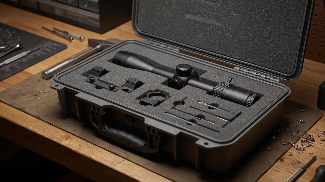
The governing specification for a composite molding case is not wall thickness but whether the mold surface still sits inside its original contour and cleanliness window when the case is opened. Composite molds are usually built as a thin shell on a load-bearing frame. Absolute strength is respectable, yet bending stiffness is often only a third to a half that of a steel mold of similar size. Surface contour is normally held to the 0.1 mm order, and the parting line and seal grooves tolerate even less local abuse. Lose a support point, or let the restraints go slack, and self-weight plus road vibration produce elastic deflection that can leave permanent damage at the bond line between shell and frame. The same shipment often carries autoclave door flanges, press platens, resin metering pumps and vacuum consumables, all of which fear contamination, corrosion and damaged sealing faces. A composite molding case therefore has to run two protection lines at once: against loss of stability, and against contamination.
This article is written for maintenance and process engineering teams at composite part producers, molding equipment builders, mold makers and spare parts distributors. It works through surface support datums, cleanliness control, release agent residue management, vacuum consumable packing, autoclave and press hydraulic components, temperature control and regulatory questions for resins and hardeners, and test criteria with on-site re-measurement, closing with a selection matrix, cost structure, FAQs and further reading.
Contents
- The first difficulty: instability and contamination
- Failure spectrum and load characteristics
- Support and lifting datums for the mold surface
- Cleanliness control and release agent residue
- Vacuum bag film and sealant tape in transit
- Press and autoclave parts: hydraulics, heating, flanges
- Temperature control and compliance for resins
- What fibre dust demands from packing and work practice
- Case structure, sealing and ocean-freight dehumidification
- Test programme and acceptance criteria
- Unpacking, re-measurement and installation
- Selection matrix and cost breakdown
- Customisation workflow and supply models
- Frequently Asked Questions
- Conclusion and related reading
The first difficulty: instability and contamination
A composite mold is structurally unlike a steel stamping die. To cut weight and allow fast heating and cooling cycles, the load path runs through a steel or aluminium frame while the working surface is a carbon laminate, a glass reinforced laminate or an electroformed nickel shell, bonded or bolted to that frame. The consequence is a structure with a stiff skeleton and a compliant skin. The surface itself carries almost no load, and its dimensional accuracy depends entirely on frame stiffness and on whether the support points sit where the designer intended. Put a support under the surface area, or space supports so far apart that the frame sags at mid-span, and the surface simply follows the deflection.
Contamination follows a subtler route. Release agent residue, cured resin chips and chopped carbon dust all migrate under vibration and settle in the areas that matter most, the parting line and the seal grooves. The surface itself is fairly indifferent to a little dust, but the closing gap and the seal groove are not. A single cured resin chip trapped on the parting face produces a witness mark that reappears as a dent in every subsequent part.
Three questions therefore have to be answered before any case design begins. Where are the surface and parting line datums? Which support points are permitted? What cleanliness class does this mold have to meet? The answers decide the liner construction, the cleaning procedure and the test programme.
Failure spectrum and load characteristics
Composite processes range from autoclave and compression molding through resin transfer molding to winding and pultrusion, and each route brings a different mix of shipped components. The table groups them by failure logic so that protection priorities can be set early.
| Component | Main failure mode | Load characteristic | Protection focus |
|---|---|---|---|
| --- | --- | --- | --- |
| Mold surface shell | Contour drift, scratches, bond line separation | Low-stiffness shell under distributed self-weight | Contoured support board, surface up, no point contact |
| Frame and stiffeners | Frame twist, cracked welds or bonds | Stiff primary load path | Multi-point support, diagonal bracing, no single-point lift |
| Parting line and seal groove | Impact witness marks, rolled edges | Local high-precision faces | Edge protectors, parting face inward, individual cover |
| Autoclave door flange | Seal groove distortion, face damage | Large thin ring, prone to ovality | Vertical cradle, six or more circumferential supports, guard ring |
| Lifting lugs and support pads | Lug tearing, thread damage | Concentrated load | Dedicated lifting gear, protective sleeves, no side pull |
| Press platen | Deflection, flatness drift | High self-weight plus vibration moment | Continuous support beams, working face up |
| Cylinder and plunger | Bore scoring, bent rod | Slender self-weight, axial impact | Axial support, rod guard, port plugs |
| Heating platens and oil channels | Distorted ports, contaminated bores | Slender parts in bending | End guards, drained and plugged channels |
| RTM metering pump | Contaminated plunger fit, corroded shaft | Close fit, fragile shaft extension | Individual cavity, shaft cap, clean packing |
| Vacuum and pressure sensors | Diaphragm loading, broken leads | Very low impact tolerance | Dedicated small cavity, coiled and fixed leads |
Two dividing lines emerge from the table. Stiff components are protected by structure; compliant, high-precision components are protected by containment and cleanliness. Both routes can share one case shell, one set of lifting points and one labelling system, but the liner zones, packing methods and work instructions must be designed separately, otherwise the heavy parts overwhelm the precise ones.
Support and lifting datums for the mold surface
The first rule of support design is that load may only enter at the points the mold designer provided. Molds normally include support pads or support faces whose local stiffness has been calculated; transit supports must correspond to those positions rather than to whatever is convenient for the packer.
Replace point support with contoured boards. For a complex surface, a contoured support board reproduces the surface shape so that the mold seats on an area rather than on points. Boards can be cast in resin, machined from laminate or assembled in segments, and should be faced with 5 to 10 mm of soft material to spread contact stress. The value of a contoured board is that it distributes reaction forces around the whole perimeter and removes local witness marks.
Calculate support spacing. Spacing cannot be chosen by habit. Work back from the frame section inertia and the permitted deflection, taking allowable deflection as no more than half the surface contour tolerance and applying a dynamic factor of 1.5 to 2.0. If only two supports are possible, for example because the site has nothing but a forklift, a rigid support beam must be fitted inside the case to convert point support into line support. The beam itself should deflect no more than one fifth of the mold's allowable deflection.
Lifting. Use the designed lifting lugs or a dedicated spreader beam, and never sling directly around the surface or the frame edge. Keep the sling angle within 60 degrees; wider angles create large horizontal components that squeeze the frame walls. Wide molds need a spreader. During lifting the surface should face the non-contact side of the case, and the parting line should face inward behind an edge protector.
Restraint. Supports handle the vertical direction, restraints handle the horizontal one. Adjustable side blocks with soft facings should limit horizontal movement without clamping, because clamping introduces stress at the mold edge and can mark the surface. Tall, narrow molds stored upright also need an anti-tip structure.
Cleanliness control and release agent residue
Cleanliness requirements come from the customer's process, not from the case supplier. Aerospace composite parts are often demolded and laid up in areas controlled to ISO 14644-1 Class 7 or Class 8, and a mold entering such an area cannot normally be cleaned again on arrival. If the case introduces particles through its liner, through the closing operation or through outgassing in transit, the mold has to be re-cleaned before first production, which costs schedule as well as labour. Comparable practice for controlled environments is described in cleanroom equipment component protection.
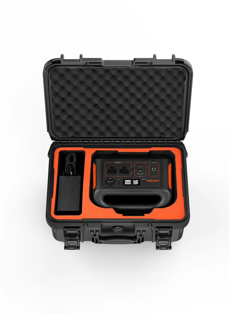
Liner materials. Anything touching the surface must be low-particle, low-outgassing and silicone-free. Clean grades of EVA, cross-linked PE foam, aluminium foil laminate and non-woven facing qualify. Untreated timber, paper-based fillers and plasticised soft PVC should never contact the surface, because they release debris or exudates under temperature cycling and vibration. Where the case structure itself is timber, a continuous isolation layer must sit between the wood and the mold.
Two-layer packing. The recommended arrangement is a clean inner bag inside a structural outer case. The surface is first enclosed in a heat-sealed clean bag or vacuum bag with a low-outgassing desiccant, and the outer case then provides the load path and transit protection. Even if the outer case is contaminated during handling, the surface remains inside a controlled envelope. Bagging should be carried out in an area no dirtier than the target class.
Release agent decisions. This is a contractual item. If the mold ships with a release coating that must be preserved, the packing label must state clearly that the coating is to be retained and that wiping and solvents are prohibited, and the liner must not react with the coating. If a clean surface is required instead, cleaning has to be completed before dispatch. A workable sequence is single-direction wiping with lint-free cloths and a solvent compatible with the resin system, changing cloth face frequently, followed by drying with clean gas. Solvent choice must suit the surface material; electroformed nickel shells and some laminates are sensitive to particular solvents, so a small-area trial is worth the time.
Judging residue. A water break test is the usual field check. Pure water is spread over a local area; a continuous film that holds for a typical 30 seconds pass criterion indicates a clean surface, while rapid retraction or film break indicates hydrophobic residue. For demanding molds, a contact angle or infrared baseline can be established at first article and used for before-and-after transport comparison.
Vacuum bag film and sealant tape in transit
Vacuum consumables are low-value but essential, and poor packing shows up only at the customer site: punctured bag film, sealant tape hardened by cold, breather cloth dusty and damp. Their packing logic differs from the mold itself, and the priorities are puncture resistance, crease avoidance and moisture exclusion.
| Consumable | Main risk | Packing requirement | Storage condition |
|---|---|---|---|
| --- | --- | --- | --- |
| Vacuum bag film roll | Puncture, creases causing leaks | Core upright, rigid outer tube, no stacking load | Cool, dry, out of direct sun |
| Sealant tape | Cold hardening, flattening, surface dust | Wound on reels, interleaved release paper, separate cells | Ideally 15 to 25 C |
| Release fabric | Moisture pickup, oil marks | Foil pouch with desiccant | Long term storage sealed |
| Flow media | Crushing and deformation | No stacking load, laid flat | Dry environment |
| Vacuum hose and fittings | Collapsed hose, damaged couplings | Coiled and tied, couplings individually sleeved | Ambient |
Separate cases beat mixed loading. Vacuum consumables and small fittings belong in their own returnable case, shipped apart from the mold. Two reasons apply. The consumable case is small and cycles frequently, so it pays to be reusable and maintainable. And because consumables are mostly polymers, a damaged pack inside the mold case turns into a contamination source directly above the surface.
Cold-weather behaviour of sealant tape. Butyl sealant tape stiffens at low temperature and loses tack. Used straight after unloading, it leaks. After ocean freight or winter road transport, let the tape sit at 15 to 25 C for 12 to 24 hours before opening and use. This instruction belongs in the dispatch documentation so that the site does not mistake a temperature effect for a material defect.
Press and autoclave parts: hydraulics, heating, flanges
Equipment components in the same consignment fall into four groups, structural load carriers, high-pressure hydraulic parts, sealing-face parts and precision electrical items, and each needs a different treatment.
Autoclave door flanges. These are large thin rings, vulnerable to ovality and groove damage. Store them upright in a cradle with at least six circumferential support points, groove facing inward behind a soft guard ring. If they must lie flat, use a pallet with a circular groove so that self-weight cannot flatten the ring into an oval. Transport and marking requirements for parts forming a pressure boundary are covered in pressure vessel component packing and transport.
Press platens. The governing issue is support, not cushioning. A platen working under multiple pressure points is carried in transit by two or three supports, so the mid-span moment can far exceed the in-service value. Use multi-point symmetrical support or two longitudinal support beams, keep the working face up or inward, and never place tools on it. Cushioning belongs below the support system, not between the working face and its supports.
Cylinders and plungers. Slender parts suffer bent rods and scored bores. Support horizontally at both ends and at mid-length, never through the piston rod, fit a rigid or semi-rigid rod guard, and plug all oil and bleed ports. If vertical transport is specified, provide an upright cradle with anti-tip restraint.
Heating platens and oil channels. Channels must be drained, dried and plugged. Residual moisture inside a heating channel corrodes the bore during a long sea voyage and the damage is found only after commissioning. Ports are weak points and need end guards; long channel parts need intermediate support against self-weight deflection.
Metering pumps and injection systems. RTM and high-pressure injection metering pumps are close-fit assemblies, and any particle can score a plunger or sleeve. Use one cavity per unit with clean packaging, cap the shaft extension, and plug the inlet and outlet ports with tagged caps so that nothing is opened early during inventory checks.
Sensors and electrical items. Thermocouple, pressure and displacement sensor leads are the classic weak point. Coil the leads and secure them against repeated flexing, give each body its own small cavity, and orient diaphragms away from any bearing surface.

Temperature control and compliance for resins
Resin systems usually carry the tightest temperature requirement in the consignment, and they are also the most likely to be held up at a border.
Thermal sensitivity. Epoxy resins and many hardeners are heat sensitive. Prolonged exposure to high temperature causes partial advancement or viscosity drift that changes the process window. A sea container stacked in the sun can reach 55 to 65 C inside, well above the recommended storage limit for most resin systems. Where a long ocean voyage is unavoidable, three measures help. First, select the route and slot using the upper temperature limit stated on the safety data sheet. Second, use phase change cooling modules sized from voyage duration and heat load. Third, fit a temperature recording label so that arrival data supports a re-test decision.
Dangerous goods screening. Some amine hardeners are corrosive or environmentally hazardous, and organic peroxide initiators are strong oxidisers, so a consignment may qualify as dangerous goods. Whether a material is regulated, which UN number applies and what packing group is required must be determined item by item from the current transport regulations and the safety data sheet, never from experience alone. Regulated items must be segregated from general cargo, with separate documents and marks; see dangerous goods transport packing assessment for the screening logic.
Segregation rules. Keep resin and hardener cases away from the mold case. A leak would be extremely difficult to remove from a mold surface, corrosive hardener damages case hardware and liner, and separate cases allow independent temperature and ventilation design. If volume forces them onto the same vehicle, place resin containers in a sealed cavity with a secondary bund.
Paperwork. For cross-border orders, ship the safety data sheet, composition list and batch records with the goods, and mark the outer case with material name, net weight, UN number where applicable and an emergency contact. These documents are inspected far more often than the equipment itself.
What fibre dust demands from packing and work practice
Carbon and glass fibre debris is the contaminant specific to composite shops, and it affects packing at two levels.
Inside the case. Carbon fibre debris is electrically conductive, fine and airborne. If the case also carries electrical cabinets, sensors or servo drives, debris reaching terminals or cooling ducts can cause shorts or nuisance faults. Segregate conductive fibre products from electrical items, and where necessary add a dust barrier outside the electrical cavity.
Case materials. Fibre debris embeds in foam and fabric liners and resists cleaning. For cases intended to be reused, build the liner as replaceable modules so that a contaminated section can be swapped out rather than scrubbed. Clean with HEPA-filtered vacuum equipment and avoid compressed-air blowing, which lifts fibre debris into the whole work area, increasing respiratory exposure and allowing it to settle into any open precision cavity.
Workers. Fibre dust irritates skin and airways. Unpacking and cleaning should be done with gloves and a dust mask in a ventilated area. Trim and cleaning waste must go to the local solid waste route, not into general refuse together with the liner.
Galvanic corrosion. Carbon fibre in contact with aluminium can form a galvanic couple in damp conditions. Where carbon products travel with aluminium frames or aluminium flanges, an insulating isolation layer between them prevents contact corrosion over a long sea voyage.
Case structure, sealing and ocean-freight dehumidification
Structural selection depends on component mass, re-use cycles and distance, while sealing and dehumidification depend on voyage length and destination climate.
Sealing class. The assembled case should reach at least IP65, and IP67 for long ocean voyages or delivery to high-rainfall regions. Verification follows IEC 60529 and GB/T 4208. Note that a perfectly airtight case is not automatically better protected: temperature swings create a pressure differential, and without equalisation the case may draw in dust when opened or force the seal out of its groove. A hydrophobic breather valve equalises pressure while blocking liquid water.
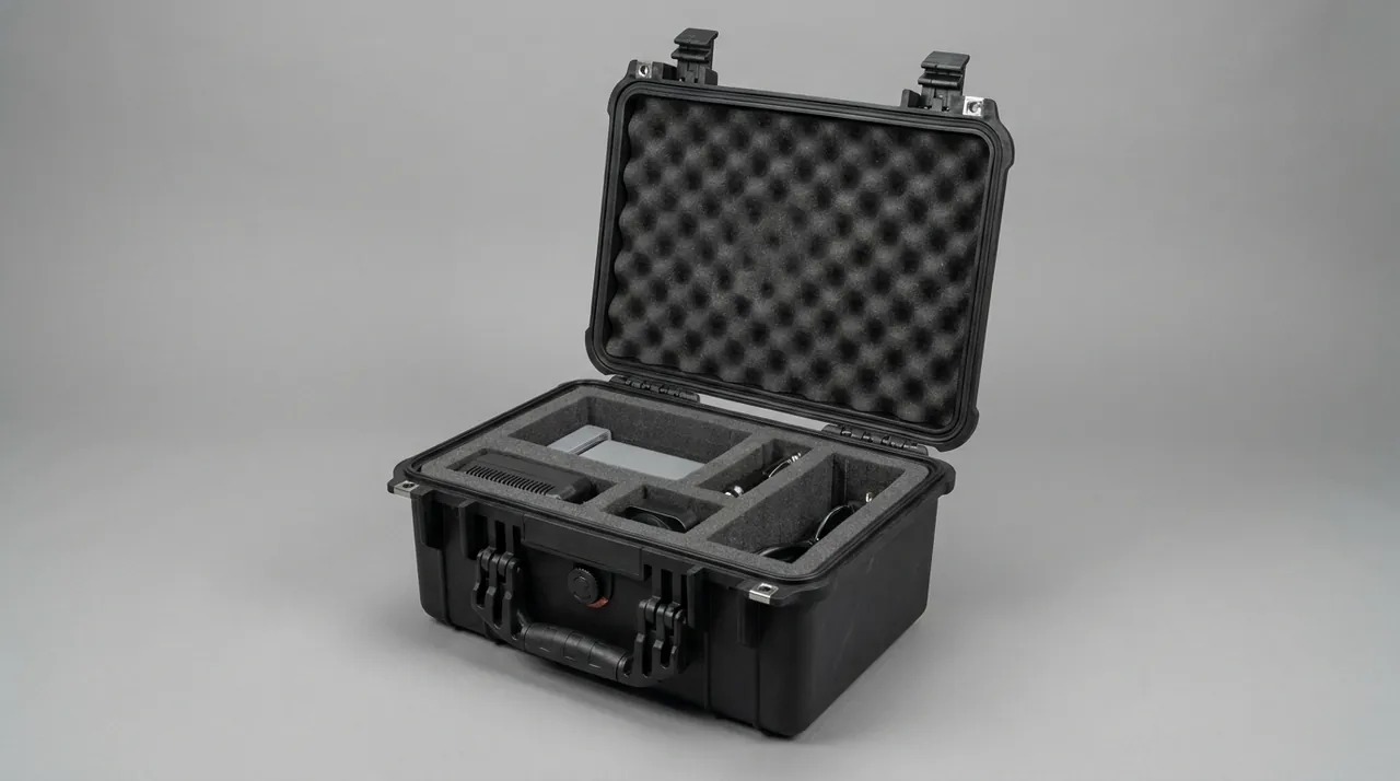
Dehumidification. Before closing, bring the internal relative humidity to 45 to 55 percent and size the desiccant from the internal net volume with at least 30 percent margin. For voyages that may exceed 30 days, use a replaceable desiccant cartridge and fit a humidity indicator so arrival checks can be documented. Timber-containing cases deserve particular attention, because untreated wood is hygroscopic and will keep releasing moisture into the case unless it is isolated or dried.
Liner matching. The liner must hold the mold without becoming a contamination source. EVA and cross-linked PE foams suit load bearing and cushioning, while clean grades suit direct contact with the surface. Where the surface has sharp edges, add a wear-resistant layer so the foam is not cut into debris. Liner machining accuracy directly affects support quality, so CNC cutting or die cutting is preferred; the process options are described in custom foam insert manufacturing.
Temperature cycling and condensation. Day-night and latitude temperature swings during a sea voyage can produce condensation inside the case. Reduce free space with liner material, raise the sealing class, and remove hygroscopic packing that has not been treated. Steel or electroformed nickel surfaces should carry a thin anti-rust film; aluminium parts must avoid anti-rust products containing copper or chlorides. Where the destination has extreme heat or cold, case materials and seals should also be checked against the guidance in case design for extreme temperature environments.
Test programme and acceptance criteria
Verification covers structure, dynamics, environment and cleanliness. Projects, sequence and sampling should all be agreed in the technical protocol before production.
| Test class | Test item | What it verifies | Acceptance basis |
|---|---|---|---|
| --- | --- | --- | --- |
| Structure | Stacking | Confirm case and liner do not collapse under long static load | Deflection within agreed limit, liner does not shift |
| Structure | Lifting and forklift | Confirm lugs, lifting points and base capacity | No permanent deformation, no cracks, hardware tight |
| Dynamic | Random vibration | Confirm supports and restraints survive long vibration | Displacement 2 mm or less, no rub marks on surface |
| Dynamic | Incline impact and drop | Confirm corner strength and cushion effectiveness | Acceleration within limit, no through-thickness liner damage |
| Environment | Temperature and humidity cycling | Confirm corrosion, condensation and material stability | No rust, no condensate, indicator unchanged |
| Environment | Spray and low pressure as required | Confirm seal integrity and pressure adaptation | No water ingress, breather valve functions |
| Cleanliness | Liner particle release | Confirm the liner does not shed | Contact faces visually clean, inner bag intact |
Where the test methods come from. Temperature, humidity, vibration and shock methods may be drawn from MIL-STD-810H, with one point made explicit: it is quoted as a method source only and confers no military certification or qualification of any kind. Movements inside China follow the GB/T 4857 series; export consignments use a distribution cycle simulation or an established industry programme. Component protection for environmental test equipment is treated in environmental chamber component protection.
Designing the surface criterion. Criteria must be measurable. The recommended primary criterion is the measured change in surface contour before and after transport. Record the key sections and datum holes before dispatch while the mold is still on its transit supports, then re-measure after arrival once the restraints are removed, the mold is on its specified supports and the temperature has stabilised. Compare the two sets against the dispatch values. A shock indicator label adds the one-off event record that helps distinguish transit shock from handling damage when a reading is out of tolerance.
Unpacking, re-measurement and installation
Site practice decides the final result, so unpacking and re-measurement should ship as a written, executable procedure.
Pre-opening checks. Inspect the outer case for damage, moisture and seal condition, then read the humidity and shock indicators before deciding to open. If a label shows an over-limit event, record and photograph it first, then follow the agreed inspection sequence. High-cleanliness molds should not be opened outdoors or in a dusty area.
Opening sequence. Remove lid, sides, restraints and support beams in that order, releasing the preload gradually so nothing shifts or topples. Bag removal matters too: wipe the outside of the bag before cutting it open in a controlled area, so that external contamination does not fall onto the surface as the bag is opened.
Timing of re-measurement. Temperature stabilisation is a precondition. Metal frames and composite surfaces expand at different rates, so a mold moved from a cold container into a warm shop drifts dimensionally and gives misleading readings. Let the mold stabilise until the surface-to-ambient difference is within the agreed band, and record the ambient temperature with the result.
Lifting handover. Use the mold's own lifting lugs and matching gear; never use the case lifting points as substitutes. The handover sheet should record lifting method, gear specification, lifting point positions and a signature line for the crew, closing the responsibility loop. Inspect the surface again immediately after lifting and photograph any new mark at once.
Last checks before installation. Three confirmations are worth making before the mold goes into the machine: that surface and parting line cleanliness meet the specification, that every port and channel plug has been removed, and that the mold has been transferred from transit supports to the machine's own support arrangement. These checks surface transit damage before first article rather than during trial moulding.
Selection matrix and cost breakdown
Four variables govern the choice: component mass and stiffness, transport mode and distance, re-use cycles, and site handling and cleanliness conditions. The table gives recommended schemes for common combinations.
| Molding scenario | Tool and part profile | Case configuration | Liner and support design | Main cost factor |
|---|---|---|---|---|
| --- | --- | --- | --- | --- |
| New mold, domestic road | Medium mold, one-way | Thick plywood case with corner protectors | Contoured board with soft facing | Structural material and lifting hardware |
| Imported mold replacement, ocean freight | Large mold, high-precision surface | Framed timber case with clean inner bag | Continuous support beams, anti-rust film, desiccant | Clean packing and dehumidification |
| Autoclave flanges and seals as spares | Large thin rings, small batches | Aluminium frame or rotomoulded case with cradle | Circumferential supports and guard rings | Cradle structure and facing |
| Vacuum consumables and small parts | Low value, high frequency, returnable | Rotomoulded returnable case with replaceable hardware | Die-cut cavity array with separate cells | Hardware life and liner modules |
| Internal shop transfer | Medium mass, short distance | Rotomoulded case with castors and tow point | Modular combination liner | Mobility hardware and reinforcement |
Composite molding (SMC/BMC or RTM) is centred on the mould and press; the moulding compound cost per part is stable and tooling amortisation falls sharply with volume, which suits medium to high batches. A representative breakdown is moulding compound and gelcoat 35 to 50 percent, mould and press tooling 12 to 20 percent, liner and cradles 22 to 32 percent, painting and corrosion protection 8 to 14 percent, and hardware with marking 4 to 8 percent. Moulded-case cost tracks the mould platen area and clamp force: a larger projected area needs higher clamp force and bigger tooling, so boxing the large shell separately from liner spares is usually cheaper than one integral oversized case and stacks better in transit. For single molds and small batches, tooling is usually unnecessary; CNC machining combined with structural fabrication meets the requirement at lower upfront cost. Amortisation logic for case tooling is set out in custom case tooling investment and amortisation.
Customisation workflow and supply models
Five stages keep the project controllable, each with a defined deliverable.
- Technical input: mold and equipment drawings, measured dimensions, mass and centre of gravity, surface and parting line locations, permitted support points, cleanliness target, transport mode and route, handling equipment, re-use cycles and whether temperature-controlled items such as resin are included.
- Design and calculation: support layout with deflection check, case structural selection, liner material and zoning, clean packing method, sealing and dehumidification, issued as drawings with the calculation note.
- First article and verification: build the first unit and run a full pack, lift and open-close rehearsal with the real mold or an equivalent mass, with cleanliness and drop screening where required.
- Sign-off and pilot build: once fit and working sequence are agreed, lock the process parameters and the cleaning routine.
- Batch production and pre-shipment audit: audit against the agreed sampling plan, then release the packing list, cleaning log and inspection log.
Two first-article actions matter particularly for composite work. The first is a lifting rehearsal, because wrong lifting points, excessive sling angles and an offset centre of gravity only reveal themselves under load. The second is a cleanliness rehearsal, which confirms that the bagging area, bag removal sequence and cleaning tools are practical before production scheduling depends on them.
On supply models, standard returnable cases are available from stock, while large mold cases and machine-line packing cases are built to drawing. For molding equipment builders, complete packing schemes can be aligned to the assembly takt, including packing process documents and on-site work instructions. All cases are manufactured and delivered by Kexin New Materials (Guangdong) Co., Ltd., whose business covers wholesale, agency, OEM/ODM production and global supply. For composite molds and press components, the two parties can agree in contract the scope and frequency of third-party testing and material documentation, including material composition statements, load calculation reports and test records produced to the agreed standards.
Frequently Asked Questions
Q: What is the most commonly overlooked damage to a composite mold in transit? A: It is contour drift with no visible mark. Impact damage and scratches are seen at unpacking, but this class of damage only appears at mold closing or first article, as uneven closing gaps, varying part thickness or local resin richness. The usual cause is a support placed wrongly, sitting on the surface area or on a weak frame section, so vibration lets the frame sag at mid-span and the surface follows. Even where the material never yields, the bond between laminate and frame can micro-crack. A second hidden mechanism is horizontal movement, where the mold slides slightly inside the case and the parting line frets against a hard surface, leaving faint witness marks. Three countermeasures work well together: allow supports only at the designed support pads, fit adjustable side blocks to limit horizontal movement, and measure key sections before dispatch and after arrival so that decisions rest on data rather than on visual impression. It also helps to record the support arrangement used during each measurement, because a mold measured on different supports is not measured under the same conditions.
Q: What cleanliness class does a mold surface need, and how does the case match it? A: The class is set by the customer's molding area, not by the case supplier. Aerospace composite work is often demolded, laid up and cured in areas controlled to ISO 14644-1 Class 7 or Class 8, and a mold arriving there frequently cannot be cleaned a second time, so packing has to deliver the target class at the moment of opening. The case matches it in three layers. The contact layer must be clean-grade EVA, cross-linked PE or aluminium foil laminate, never untreated timber, ordinary paper filler or plasticised soft PVC. The enclosure layer should be a clean inner bag, heat sealed, inside a structural outer case that carries the loads, keeping contamination outside the bag. The work environment is the third layer: bagging and bag removal both belong in an area no dirtier than the target class, with clean clothing and gloves. Miss any layer and the inside of the bag cannot be guaranteed. Put the class, the contact material list and the bagging requirements into the technical protocol.
Q: How should lifting points be determined, and can a forklift be used directly? A: Lifting must use the lugs or support pads the mold designer provided. Never select a position on site, and never sling around the surface or the frame edge. Lifting is a concentrated load case whose local stresses usually exceed those of uniform transit loading, so an unverified position can cause permanent deformation or break the bond line the moment the load comes on. Keep sling angles within 60 degrees, because wider angles generate large horizontal components that squeeze the frame walls, and use a spreader beam for wide molds. Direct forklift handling of the mold body is not recommended. Fork tines rarely line up with the designed support points, and the hydraulic lift introduces shock. If a forklift is the only option, provide dedicated fork pockets in the case or pallet so that tine reaction goes into the structure, let the pallet carry the mold, limit travel speed and avoid sharp turns or sudden stops while loaded.
Q: How clean must the surface be before dispatch, and should the release layer be kept? A: Both approaches are valid, but the choice must be made explicitly and stated on the packing label. The worst outcome is a half-cleaned surface, partly wiped and partly coated, because subsequent cleaning becomes harder. Where a clean surface is required, work by single-direction wiping with lint-free cloths and a solvent compatible with the resin system, changing the cloth face frequently so that removed residue is not spread back over the surface, then dry with clean gas and confirm with a water break test. Where the mold ships with a release coating that must be preserved, choose liner materials that will not react with it and label the case to prohibit wiping and solvent contact. In either case, establish a cleanliness baseline at first article so that before-and-after transport comparison is possible. Solvent selection must suit the surface material, since electroformed nickel shells and some laminates are sensitive to particular solvents, and a small-area trial is always worth the time.
Q: Can resin and hardener travel in the same case as the mold? A: It is not advisable unless volume genuinely prevents separation and full isolation is provided. Three reasons argue for separate cases. First, leakage risk: resin reaching a surface or parting line is extremely difficult to remove and may require surface reprocessing. Second, the temperature requirements differ, since resin systems have upper storage limits while containers routinely reach 55 to 65 C inside during ocean freight, so cooling measures and routing decisions are needed for the resin but not for the mold, and combining them raises both difficulty and cost. Third, compliance risk: some amine hardeners are corrosive or environmentally hazardous, and organic peroxide initiators are strong oxidisers, so the consignment may be classified as dangerous goods requiring a specific UN number and packing group, and regulated cargo cannot be mixed with general cargo on one document. If co-loading is unavoidable, seal the resin in its own cavity with a secondary bund, document and mark it separately, and ship the safety data sheet and emergency contact with the goods.
Q: After an ocean shipment, how do you tell whether surface deviation came from transport or from installation? A: Build a three-point data chain rather than relying on a single measurement. Before dispatch, measure key section contour and datum hole positions while the mold sits on its transit supports, recording ambient temperature and support arrangement. After unloading, check appearance and indicator labels before releasing any restraint. Then remove the restraints, place the mold on its specified supports, let the temperature stabilise and measure again. Finally, measure once more after the mold is located in the machine. Deviation between the first and second measurements points to transport; deviation between the second and third points to lifting or installation; if those two agree closely yet closing still fails, check datum transfer and tooling fit. Use differences rather than absolute values, because site support and measurement datum affect absolutes. Temperature stabilisation is a precondition throughout, since metal frames and composite surfaces expand differently and measuring a cold mold in a warm shop produces misleading numbers. Keep the three measurement records, with temperatures attached, in the handover file; if a contour argument arises later, they are the only way to trace when the change actually happened.
Q: How should vacuum bag film and sealant tape be packed? A: Their packing logic is quite different from the mold's, and the priorities are puncture resistance, crease avoidance and moisture exclusion, so a separate case is preferable to mixed loading. Bag film arrives as a roll; store it with the core upright inside a rigid outer tube, and never stack loads on it, because creases are the main cause of leaks and creases form under pressure, only to be discovered when the film is unrolled on site. Sealant tape should be wound on reels with release paper between layers and stored in separate cells, ideally at 15 to 25 C; butyl tape stiffens and loses tack when cold, so after ocean freight or winter road transport let it stabilise at room temperature for 12 to 24 hours before opening, otherwise the site may misdiagnose a temperature effect as a material defect. Release fabric and flow media need sealed, desiccated packing. A separate consumable case has a further benefit: being small and frequently cycled, it can be reused and maintained independently, and a contaminated liner module can simply be replaced.
Q: How should liner material be chosen so that it does not contaminate the surface? A: Judge against three requirements: it must not shed particles, must not outgas and must contain no silicone. For the layer touching the surface, use clean-grade EVA or cross-linked PE foam, with a non-woven or aluminium foil laminate facing where extra isolation is needed. Load-bearing layers can use denser, harder EVA or EPP, but they must be a separate layer from the contact layer, so that load capacity is not bought at the expense of cleanliness. Materials to avoid include untreated timber and paper filler, which shed debris and absorb moisture under temperature cycling; plasticised soft PVC, which can leave exudates on the surface; and open-cell foam, which traps and slowly releases dust. Where the surface has sharp edges, add a wear-resistant isolation layer at the contact point so foam is not cut into fragments. Liner machining accuracy matters as much as material choice: CNC or die cutting gives an even gap between cavity and surface, whereas an oversized gap lets the mold move under vibration and an undersized one scratches the surface during packing.
Conclusion and related reading
The hard part of a composite molding case is fitting two contradictory protection goals into one packing system. A compliant mold surface that fears instability needs multi-point or area support along a rigid load path. A parting line and seal groove that fear contamination and impact need clean enclosure and individual guarding. Autoclave door flanges, press platens, cylinders and metering pumps then add their own risks of ovality, deflection, corrosion and particle damage. The effective answer is not a thicker case. It is confirming the surface datums, permitted support points, cleanliness target and lifting method at design stage, and then proving the packing with a lifting rehearsal and a cleanliness rehearsal at first article. For buyers, handing over the mold drawing, mass and centre of gravity, support point positions and transport route in one pass remains the cheapest way to shorten the communication cycle and avoid rework after production starts.
For comparable equipment protection logic, see forging die and tooling transport schemes and casting mold transport and lifting. For test programme structure and sampling, implementing transport packaging test procedures offers a workable framework.
Related reading