

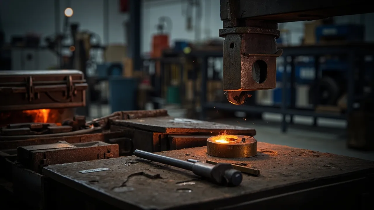
Forging dies and forgings present the most extreme load case in packaging engineering: steel dies weighing hundreds of kilograms to several tons, forgings carrying residual heat, scale and burrs, and a shop environment that already involves heavy crane handling and heavy-vehicle transport vibration. The headline conclusion is that the design priority for this case class is not moisture or dust but the correct sequence of three tasks: structural load bearing, impact energy absorption, and surface protection. Structure transfers weight evenly to the floor or pallet, elastic elements absorb the energy of drops and impacts, and machined support blocks plus cut liners isolate the dovetail, keyway, cavity face and parting line. Any design that tries to combine all three tasks in a single material will show displacement, crushing or distortion after a few thousand kilometers. Sealing to IP65 under IEC 60529 and GB/T 4208 is only the sealing threshold. For forging tooling, what determines the delivery pass rate is support contact ratio, the number and location of tie-down points, and how much the case deforms after a 48-hour stacking test.
This article is written for equipment engineers and buyers at forging plants, closed-die and open-die shops, forging press manufacturers and tooling management departments. It works through hammer dies, hot forging dies, cold and precision forging dies, forgings themselves, baskets and clamping fixtures item by item, and provides heavy-load base selection tables, cushion material comparison tables and a standards reference list, together with acceptance and sampling steps that can be written straight into a procurement technical agreement. If you also manage plant-wide tooling allocation, see the instrument case selection guide for a consistent baseline.
Table of Contents
- 1. Transport Risk Profile: Impact and Heavy Load Stacked Together
- 2. Hammer Dies and Hot Forging Dies: Dovetail, Keyway and Cavity Face
- 3. Cold and Precision Forging Dies: Surface Accuracy and the Dimensional Chain
- 4. Forgings Themselves: Residual Heat, Scale and Burr Handling
- 5. Heavy-Load Support: Steel-Timber Composite Bases and Support Face Design
- 6. Lifting and Tie-Down: Lift Points, Sling Angle and Overturning Prevention
- 7. Cushioning and Energy Absorption: Why Foam Cannot Carry Heavy Loads Alone
- 8. Corrosion and Moisture Control: Delivery Appearance Requirements for Tool Steel
- 9. Case Structural Strength: Stacking, Forklift Pockets and Reinforcing Ribs
- 10. Sealing and Pressure Equalization: When They Must Be Fitted
- 11. Transport Verification and Standards: Drop, Vibration and Stacking
- 12. Handling Practice and Delivery Acceptance Points
- 13. OEM/ODM and Volume Supply Collaboration
- Frequently Asked Questions
- Conclusion & Related Reading
1. Transport Risk Profile: Impact and Heavy Load Stacked Together
Forging logistics has a distinctive character: heavy loads, rough handling, long distances, and a packaging budget that is often squeezed by the assumption that steel cannot be damaged. The result is a batch of dies that arrive with no visible damage and still fail on installation: an indented dovetail, a locally crushed keyway, a chipped cavity face, plastically deformed mounting faces. None of these defects scrap the die, but each one destabilizes the dimensional chain, causing mismatch or excessive flash.
Six risk categories need separate treatment.
First, high-energy impact. Forging dies commonly weigh between 100 kg and 5000 kg. For the same 30 cm drop, impact energy scales with weight, and the peak force generated by a 2 t die is enough to crush the timber skid and punch through the case floor. Drop protection for heavy loads is not about thicker foam; it is about reducing the probability of a drop and spreading contact stress.
Second, fastener relaxation and displacement under sustained vibration. The vibration spectrum of road transport concentrates between 3 Hz and 30 Hz, which overlaps the natural frequency range of heavy items on elastic supports. If support stiffness is wrong, the die creeps inside the case, bolt preload decays, and displacement and collision follow.
Third, support-face crushing and mounting-face distortion. The die base is normally a ground mounting surface. If the support face is not flat, load concentrates on one or two high points, contact stress far exceeds the compressive strength of timber perpendicular to grain, the support crushes, and the mounting face deforms plastically. The working requirement is a support contact ratio of at least 80 percent.
Fourth, surface damage to cavity face, parting line and dovetail. These three features carry the accuracy of the die. The dovetail locates a hammer die on the ram, and the keyway transmits torque; once either shows indentation or crushing, the clamped assembly develops clearance and forging mismatch increases.
Fifth, residual heat and scale on forgings. Forging shops either pack hot or pack after cooling. A hot forging may still be at 200 C to 600 C on the surface, which softens or burns through ordinary foam liner, while mill scale is hard and sharp and acts as abrasive contamination for the case and liner.
Sixth, corrosion and oil. Tool steel develops condensation corrosion in humid conditions, while graphite lubricant, release agent and rust-preventive residue on forgings contaminate the liner and reduce friction so that restraint fails.
Put these six together and the conclusion is that a forging tooling case must be designed around structural strength as the main line, not sealing rating. For seal material selection in heavy-load, oil-bearing and temperature-cycling conditions, see protective case seal materials.
The table below gives reference protection parameters for common forging items.
| Item | Typical weight | Primary risk | Recommended base or liner | Buffer thickness | Notes |
|---|---|---|---|---|---|
| --- | --- | --- | --- | --- | --- |
| Large hammer die | 1000-5000 kg | Support crushing, dovetail crushing | Steel-timber composite frame plus PU blocks | 20-30 mm | Support contact ratio at least 80 percent |
| Medium hot forging die | 300-1000 kg | Mounting-face distortion, cavity impact | Timber skid plus steel base rails | 20-30 mm | At least four tie-down points |
| Small hot forging die | 50-300 kg | Parting-line impact, corrosion | PE cut liner plus VCI film | 20-30 mm | Parting line up, cover fitted |
| Cold and precision forging die | 30-500 kg | Surface accuracy loss, dimensional drift | EVA liner plus individual cells | 20-30 mm | No hard contact on working face |
| Forging, medium to large | 50-2000 kg | Residual heat, scale, corner impact | Timber skid plus local rubber pads | 15-25 mm | Remove scale first |
| Precision forging, small | 5-100 kg | Surface indentation, dimensional change | EVA shallow individual cells | 15-25 mm | Never stack |
| Basket and tray | 30-500 kg | Stack crush, corner deformation | Timber skid plus rubber pads | 15-25 mm | Limit stack height |
| Clamping fixture and jig | 10-150 kg | Locating surface scoring, distortion | PE and rubber pads, zoned fixing | 15-25 mm | Protect locating surfaces |
| Scale and shot, bulk | 20-500 kg | Abrasive contamination, bag rupture | Dedicated sealed container plus absorbent pad | Not applicable | Handle per waste rules |
2. Hammer Dies and Hot Forging Dies: Dovetail, Keyway and Cavity Face
Hammer dies and hot forging dies are the most frequently used tooling in a forging shop and the class where the conflict between weight and precision is sharpest.
The dovetail is the mounting datum of a hammer die. The die is fixed to the ram through the dovetail and a wedge or clamp, and the angled dovetail faces determine location and resistance to movement in the striking direction. Once the dovetail shows indentation, burrs or local crushing, clamping leaves clearance, forging mismatch grows and the die loosens early. In transport, dovetail damage almost always comes from one of two packing arrangements: the dovetail resting directly on the case floor, or two dies pressing their dovetails against each other. Fit a dedicated protective block, in laminated timber or polyurethane, so that the block rather than the dovetail contacts the support face, and when several dies share a case, orient all dovetails the same way and keep them from touching.
Keyways and locating faces. A keyway transmits torque or limits circumferential movement, and its width tolerance is usually tight. Impact crushes the side walls, and the key then will not seat. Insert a soft protective strip into the keyway and add an external cover plate.
Cavity face and parting line. A hot forging die cavity has usually developed thermal fatigue cracks and an oxide layer in service, and impact in transit propagates those cracks. The parting line sets flash thickness, and impact damage increases flash and reduces material yield. Stand the die with the parting line up, fit a rigid protective cover, and lock that cover with the same fasteners that hold the die, so the cover cannot itself become a striking object.
Die blocks and inserts. A large hammer die consists of a block body and replaceable inserts fixed by dovetail, key or bolts. Remove and pack inserts separately before shipment, or fit positive stops, so that they cannot shift inside the case and damage mating faces.
Ejection and locking mechanisms. Ejector pins, springs and wedges can loosen or shift under vibration. Inspect and lock each one before packing, or remove and pack separately.
Preheating and residual heat. Forging dies normally run preheated at 200 C to 350 C, and packing hot brings that heat into the case. Liners and molded case parts soften and distort under sustained heat, so the working rule should be that a die is packed only after it has cooled to ambient or below 50 C. That is a work-practice requirement rather than a packaging performance issue. For material selection at elevated temperature, see extreme temperature case design.
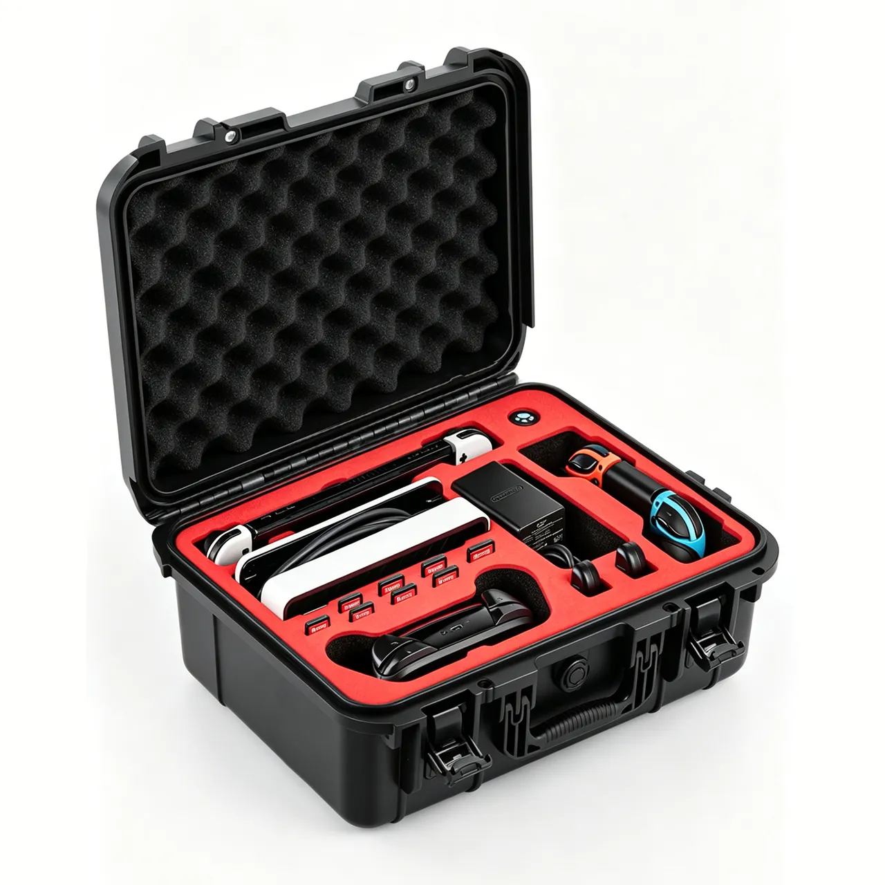
3. Cold and Precision Forging Dies: Surface Accuracy and the Dimensional Chain
Cold, warm and precision forging dies often see more concentrated working loads than hot forging dies, with working surface roughness typically in the Ra 0.2 um to 0.8 um range, and their transport protection requirements differ clearly.
First, the working surface must not contact anything hard. The working surface of a precision die, whether the cavity of the die insert or the face of the punch, is the origin of the dimensional chain. Apply peelable protective film or a soft protective pad, support the die in a contoured EVA or PU liner, and never let the working face contact the case floor.
Second, separate components that participate in the dimensional chain. A cold forging die typically consists of a prestress ring, a die insert, a punch, a backing block and an ejector. These components have mating tolerances, and if they press against each other in transit, the mating faces indent and the assembled die produces out-of-tolerance forgings. Dismantle and pack each component in its own cell; if dismantling is impossible, fit rigid spacer rings between components to prevent mutual loading.
Third, control distortion in thin-wall and slender parts. A prestress ring is a large-diameter thin-wall ring that turns oval under lateral load, and punches and ejectors are slender parts that bend. Use contoured cradles with area contact, never line or point contact.
Fourth, corrosion requirements are higher. Cold forging dies work at room temperature with no protective oxide layer, so bare tool steel corrodes more readily. Use VCI film with desiccant and determine the material grade and protection period using the approach in GB/T 4879 rust-preventive packaging, with 12 months a common specification.
Fifth, put the gentle-handling requirement in writing. Precision dies carry high value density and high repair cost. Mark the case with precision part, do not roll and do not drop, using the symbols defined in GB/T 191.
The table below compares protection orientation by die type.
| Die type | Typical unit weight | Accuracy focus | Recommended liner | Restraint method | Protection priority |
|---|---|---|---|---|---|
| --- | --- | --- | --- | --- | --- |
| Hammer die | 500-5000 kg | Dovetail fit, parting line | Steel-timber base plus dovetail blocks | Clamps and bolts, four points minimum | Heavy support, dovetail protection |
| Hot forging press die | 300-2000 kg | Cavity face, guide pillars | Timber skid, steel rails, EVA | Clamps plus lateral stops | Contact ratio, no displacement |
| Cold and precision die | 30-500 kg | Working roughness, fit tolerance | Contoured EVA or PU individual cells | Separate fixing per component | No hard contact on working face |
| Roll forging die | 200-1500 kg | Roll groove, journals | Contoured cradle plus journal sleeves | Journal clamps plus straps | Prevent rotation and journal damage |
| Ring rolling die and mandrel | 100-800 kg | Ring working face, roundness | Area-contact contoured cradle | Radial stops | Prevent oval distortion |
| Extrusion die and punch | 20-300 kg | Working face, coaxiality | PU individual cell plus rigid sleeve | Independent fixing | Prevent bending in slender parts |
4. Forgings Themselves: Residual Heat, Scale and Burr Handling
Protection requirements for the forgings themselves are often underestimated, on the intuition that a forging is already a rough part. In practice, transit damage turns directly into insufficient machining allowance or rework downstream.
First, residual heat must be handled. A forging off the line may have a surface at 200 C to 600 C. Packing hot causes three problems: softening or burning of foam liner and molded case parts; a pressure differential as the heated internal air expands and then cools, repeatedly compressing the gasket; and condensation during cooling. State the working rule that forgings are packed below 50 C, or agree a short-term temperature limit for case and liner materials in the contract.
Second, mill scale must be removed. Iron oxide scale is hard and sharp, and under transport vibration it acts as an abrasive that grooves the liner and contaminates the surface of other forgings. Clean with a wire brush or blasting before packing, and handle the removed scale separately as solid waste.
Third, burrs and flash must be removed. A burred forging moving relative to its neighbours cuts into adjacent forgings and liner like a blade. Deburr before packing and add separators between forgings.
Fourth, individual cells for precision forgings. For forgings with tight dimensional tolerance and high surface requirements, such as blades, gear blanks and connecting rods, use EVA shallow individual cells with one part per cell and no stacking. Stacking puts the full weight of the upper part on the top surface of the lower one, producing indentations that may still be visible after machining.
Fifth, separate bulk and abrasive materials. Scale, steel shot and blast media must be carried in dedicated sealed containers and never loose in the case. These materials are industrial solid waste or reclaimable material and should be handled accordingly. The protective case is not used as a waste or hazardous waste container.
Sixth, grade the rust protection requirement. Not every forging needs rust prevention. Carbon steel forgings in dry short-term storage may need nothing; alloy steel forgings, pre-machined forgings and forgings on long sea routes should be treated. Determine the scheme from three variables: transit duration, destination climate and downstream process.
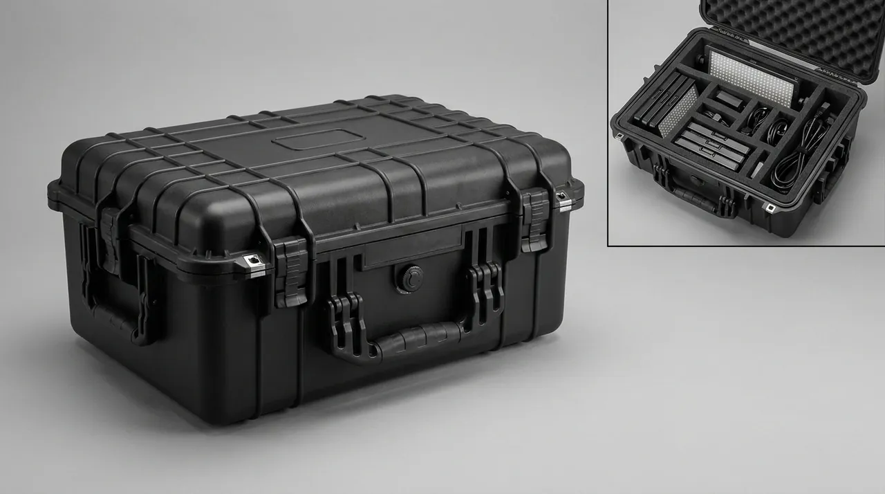
5. Heavy-Load Support: Steel-Timber Composite Bases and Support Face Design
Heavy-load support is the technical core of a forging tooling case. An under-designed base lets the die shift within weeks, while an over-designed base produces a case too heavy for the equipment on site.
The support contact ratio is the first metric. The working requirement is at least 80 percent. Raise it by machining a contoured support to the actual shape of the die base, in PE, laminated timber or polyurethane, rather than laying the die on a flat board. For a die base with lightening pockets or steps, a contoured support is essentially the only workable solution.
Select the base format by weight band.
| Die unit weight | Base format | Main load-bearing member | Tie-down points | Suitable transport | Notes |
|---|---|---|---|---|---|
| --- | --- | --- | --- | --- | --- |
| 50-300 kg | Solid timber skid (plywood plus timber) | Timber longitudinal rails | 4 | Road, air | Forklift pocket at least 90 mm |
| 300-1000 kg | Timber skid plus steel base rails | Channel or square tube plus timber | 4-6 | Road, LCL sea | Rubber pads between rail and die |
| 1000-3000 kg | Steel-timber composite frame | Welded steel frame plus timber deck | 6-8 | FCL sea, dedicated vehicle | Mark lift points and center of gravity |
| 3000-5000 kg | Heavy steel frame plus dedicated clamps | Structural steel weldment | 8 or more | Dedicated vehicle, flat rack | Lifting and tie-down calculation advised |
| Above 5000 kg | Dedicated tooling, split shipment | Project-specific | Project-specific | Project logistics | Consider dismantling or splitting |
The division of labor between structure and elasticity belongs on the drawing. Structure carries the weight, elastic elements absorb impact, and cut liners do the locating. Asking foam to carry weight and locate at the same time is the most common error in heavy cases. Foam creeps under sustained load, and long-term compression set can exceed 10 percent, so within weeks the die shifts and begins striking adjacent parts or the case wall.
Lateral restraint is not optional. Vertical support solves crushing; lateral stops solve collision. Place timber or polyurethane stops around the die with a 2 mm to 5 mm gap to the die sides, so the die has no distance in which to accelerate horizontally. For the selection logic behind elastic supports, see cushion liner and energy absorption design.
6. Lifting and Tie-Down: Lift Points, Sling Angle and Overturning Prevention
Lifting and tie-down is the highest-risk stage for forging dies, both for damage and for safety.
Lift points must be defined and marked. Large dies normally have lifting lugs or threaded lifting holes. Where a die has none, settle the whole-case lifting plan at the packaging design stage and mark the case with the permitted method. Do not sling the die body directly with wire rope, because contact between rope and die edge produces extremely high local compressive stress, damaging both the die and the rope.
Center of gravity marking and eccentricity. An eccentric die tilts during lifting, and the lateral force of that tilt slides it inside the case. Mark lateral and longitudinal center of gravity on the outside of the case, add a no-side-tilt symbol, and for strongly eccentric dies add lateral stops inside.
Sling angle directly affects restraint force. The smaller the angle between strap and horizontal, the smaller the vertical clamping component and the weaker the restraint. As a working rule keep the angle at 45 degrees or more, with 45 to 60 degrees the ideal band, and increase strap count or switch to clamps when the angle must be smaller. Also account for strap elongation. Nylon stretches noticeably under load and relaxes progressively under transport vibration, so prefer low-stretch polyester straps or schedule a mid-route re-tensioning check.
Choosing tie-down points. Forces should bear on mounting holes, lifting lugs, dedicated slots or base steel rails, never directly on the cavity face, parting line or dovetail flank. Use at least four tie-down points arranged symmetrically so the die cannot slide in one direction.
Overturning prevention. A high-center-of-gravity die such as a vertical extrusion die tips under hard braking. Lay tall dies down for transport where the machined faces allow, or use a dedicated vertical frame with a wider base span. For case mobility fittings, see case wheels and trolley handle design.
7. Cushioning and Energy Absorption: Why Foam Cannot Carry Heavy Loads Alone
The most common misconception in heavy-load protection is equating thick foam with good cushioning. For a forging die, that equation does not hold.
First, foam has limited load capacity. Typical EVA and PE foams have compressive strength in the 0.05 MPa to 0.5 MPa range depending on density and formulation. If a 2000 kg die transfers its weight through four contact patches of 50 mm by 50 mm, contact stress is roughly 2 MPa, far above the elastic range of ordinary foam, which then crushes and loses all cushioning ability.
Second, foam creeps under sustained load. Even within the elastic range, long-term loading produces compression set, which shows up as a case that fitted perfectly at packing time and has clearance on arrival. Once clearance exists, vibration gives the die room to accelerate and strike.
Third, the correct division is structural bearing, elastic absorption and area-contact load transfer. Specifically: support the die on steel or timber structural members, insert a 10 mm to 20 mm rubber or polyurethane pad between them at 60 to 80 Shore A so that load transfers through area contact and high-frequency vibration is damped, then place a 20 mm to 30 mm elastic layer between the base and the case shell to absorb the low-frequency energy of handling drops and vehicle impacts.
Fourth, match the absorbing material to the impact level. For high-energy impact, PU foam and EPP absorb more efficiently than EVA and PE. For repeated transshipment, EPP holds its recovery better. For oil-bearing environments, choose oil-resistant rubber or closed-cell material. See case foam material comparison.
Fifth, cushioning design needs verification. Buffer thickness and material hardness cannot be set from experience alone. Confirm them with loaded drop and vibration tests, using three simultaneous criteria: no damage, no displacement, no loosened fasteners. For impact test design logic, see seal and shock resistant case design.
8. Corrosion and Moisture Control: Delivery Appearance Requirements for Tool Steel
Corrosion on a forging die is a delayed failure: it passes outgoing inspection, rust appears on arrival, and responsibility is hard to assign. Rust prevention therefore deserves its own clause in the technical agreement.
First, define the protection period and the criterion. Common periods are 6, 12 or 24 months from packing completion. Write the criterion as no visible rust on cavity face, parting line, dovetail and mounting face at opening. Determine the material grade using the approach in GB/T 4879 rust-preventive packaging.
Second, VCI plus desiccant is the mainstream solution. VCI material releases an inhibiting vapor inside an enclosed space and suits complex surfaces such as cavities and dovetails. The rules are: VCI must form a reasonably enclosed volume; VCI does not replace drying and must be combined with desiccant; and copper and aluminum parts need a compatible formulation because amine-based inhibitors corrode them.
Third, size the desiccant by volume and scale it by scenario. The working figure is 100 g of silica gel per 50 L of internal volume, increased by 1.5 to 2 times when transit exceeds 30 days, when the destination port is hot and humid, or when the case seals below IP65. Desiccant needs an enclosure to work in, so the case sealing rating is the precondition for any drying strategy. For the sealing requirements involved, see the IP67 protective case design.
Fourth, match oil and rust preventive to the downstream process. Some forging dies are cleaned before installation, and residue that is hard to remove affects the preheated surface condition and the forging surface quality. Require a cleanability specification for the rust-preventive material.
Fifth, container rain is the biggest variable. As a container crosses climate zones, the day-night temperature swing makes moisture condense on the roof and drip down. Countermeasures include an adequate desiccant charge and humidity indicator cards, a case sealing to IP65 or better, a moisture barrier between pallet and case floor, and avoiding opening the case in rain or during humid periods. For overall case protection logic, see waterproof case and IP rating implementation.
9. Case Structural Strength: Stacking, Forklift Pockets and Reinforcing Ribs
For a forging tooling case, case strength is a quantifiable engineering metric rather than an adjective.
First, stacking strength needs test evidence. Sea freight and warehousing commonly require two or three high stacking, and a single case with contents can weigh several tons. Verify the deformation of the middle case with a 48-hour or 72-hour static stacking test and define the maximum permitted deformation. A stacking test is the most direct way to turn adequate strength into a number.
Second, impact resistance can cite an IK rating. IEC 62262 defines IK ratings from IK00 to IK10 to characterize a enclosure's resistance to mechanical impact. For a forging tooling case, citing an IK rating gives the shell's impact resistance a comparable quantitative basis, which suits the shell clause of a procurement agreement particularly well.
Third, put forklift and lifting apertures on structural beams. Forklift pocket height should be at least 90 mm as a working figure, with chamfered or steel-edged entries so repeated fork insertion does not split the deck. Lifting points belong at steel frame nodes, not on case walls or timber panels.
Fourth, align reinforcing ribs with the load path. Ribs spread concentrated load over a larger area. A common error is adding ribs to the middle of the side wall when the actual load path runs die, support, base rail, forklift pocket or floor. Reinforcement belongs at the base rails and corner fittings; ribs in the middle of a side wall contribute little to load bearing.
Fifth, balance case self-weight against handling capability. A steel-timber composite frame is strong but heavy. If the customer site has only ordinary forklifts or a 2 t pallet truck, optimize the structure rather than adding material. Confirm the customer's handling equipment at the proposal stage, so the case is not built heavier than the site can move. For service life and maintenance assessment, see protective case service life.
10. Sealing and Pressure Equalization: When They Must Be Fitted
Sealing and pressure equalization are not a case of higher specification always being better. They follow the scenario.
First, scenarios that require sealing. These include sea freight or cross-climate long-distance transport; destinations in humid or coastal high-salt-fog regions; cases containing precision parts, bare tool steel surfaces or electrical components; and any transit period beyond 30 days.
Second, a reasonable IP starting point. Under the IP ratings defined by IEC 60529 and GB/T 4208, IP65, meaning dust-tight and protected against water jets, is a reasonable starting point for road transport, and IP67, adding temporary immersion, suits sea transshipment, open yards and rainy-season handling. An IP rating promises nothing about impact resistance, stacking strength or corrosion performance, and a higher rating does not automatically extend the rust protection period.
Third, pressure equalization must be considered together with sealing. A sealed case experiences temperature and altitude changes in transit, and the resulting differential repeatedly compresses the gasket. For a forging tooling case, packing hot adds another source of differential as internal air expands and then cools, so in any scenario where hot packing is permitted, a pressure equalization valve is essentially mandatory. For valve selection and placement, see pressure equalization valve design.
Fourth, seal material must be compatible with an oil-bearing environment. Forging shop air often carries oil mist and graphite dust, and a gasket in long contact with oil may swell. Specify the seal material type, for example nitrile or fluoroelastomer, and the oil resistance requirement in the agreement.
Fifth, scenarios where sealing is not recommended. If a case carries only rough forgings on a short road leg with no corrosion-sensitive surface, an open or semi-open ventilated crate is more economical and avoids condensation accumulation. Selection should follow risk, not a preference for the fullest possible specification.
11. Transport Verification and Standards: Drop, Vibration and Stacking
The protection level of a heavy case has to rest on a citable test framework.
The ISTA series. ISTA Series 1 covers basic performance tests, Series 2 partial simulation and Series 3 general simulation. Because forging tooling cases usually exceed 68 kg per unit, 3E for unitized loads moving as LTL freight and 3B are cited more often. For selection logic and test sequences, see the ISTA transport testing procedure.
The GB/T 4857 series. This series specifies basic test methods for transport packages, including drop, stacking, vibration, impact and water spray. Citing it in domestic contracts is easier for third-party laboratories to execute. See GB/T 4857 transport packaging in practice.
ASTM D4169. This standard is organized around a distribution cycle and combines sequences through a DC number, allowing severity to be tailored to the real logistics chain. See ASTM D4169 distribution cycle testing.
MIL-STD-810H. This standard provides environmental test methods for vibration, shock, temperature and humidity, and low pressure. State clearly that citing it means only that its methods are used as a basis for environmental verification; it does not constitute military certification or a military qualification. See MIL-STD-810H environmental test basis.
A recommended test combination. For forging dies and forgings, use four legs: edge or corner drop for handling, random vibration for long road and rail routes, 48-hour stacking for warehousing and container loading, and temperature-humidity cycling for sea freight and cross-climate routes. Drop testing must use the real loaded weight, because the failure modes of a heavy case, including skid crushing, support fracture and fastener relaxation, are entirely different from those of a light case. For cases containing precision dies, measure die position before and after the vibration test and use displacement as the acceptance criterion rather than appearance alone.
12. Handling Practice and Delivery Acceptance Points
Even a well-designed packaging scheme can be undone by one rough handling event, so work practice must be delivered alongside the packaging design.
First, lifting rules. Specify the permitted lifting methods, whether whole-case lifting, forklift from the base, or lifting by die lugs, along with sling types and the maximum sling angle. Prohibit side pulling, prohibit hanging anything from the case top, and prohibit slinging the die body directly with wire rope.
Second, a tie-down checklist. Inspect each item before loading: tie-down point count and location per the plan; strap angle within 45 to 60 degrees; straps clear of sharp edges, with corner protectors where needed; bolt preload at the specified torque; and lateral stops installed.
Third, mid-route inspection. For dies above 500 kg, schedule one mid-route check on long journeys, focusing on strap tension and signs of internal displacement.
Fourth, the opening inspection sequence. Check in this order: external symbols and appearance, gasket and pressure equalization valve, signs of internal displacement, liner crushing, die surfaces including cavity face, parting line, dovetail and mounting face, and finally forging surfaces. Keep photographs throughout. Reading displacement marks before reading damage helps separate transit damage from pre-existing conditions.
Fifth, the claim evidence chain. Claims for heavy cargo depend on the evidence chain. Supply packing photographs, tie-down photographs, support contact ratio records and test reports with the shipment, and on arrival photograph immediately and record opening time, weather and site conditions. For acceptance and sampling methods, see custom case acceptance and AQL sampling.
Sixth, reuse and maintenance. Forging tooling cases are usually reusable packaging for round-trip tooling allocation. After each return leg, inspect for crushed supports, cracked skids and aged gaskets, and replace as needed. For cleaning and maintenance practice, see how to clean a protective case.
13. OEM/ODM and Volume Supply Collaboration
Case requirements in the forging industry are noticeably project-based and customized, and the collaboration model for volume supply follows that pattern.
Typical requirement types. The first is model-based supply, where the die shop or forging plant provides 3D models and lift point information and the supplier returns a liner and base proposal. The second is line-based supply, where one forging line needs a combined package of die cases, forging cases, basket cases and tool cases, with a common base interface and stacking height. The third is annual framework supply in stages, producing against monthly or quarterly usage to reduce customer inventory pressure.
Recommended design deliverables. The proposal stage should deliver four items: the liner and base assembly drawing; the support contact ratio target and inspection method; the tie-down scheme with point locations, strap specification and preload torque; and the whole-case test plan with acceptance criteria. Turning contact ratio and displacement into numbers is the single most important technical communication device in this kind of project.
What JUNZHJIA provides. JUNZHJIA (Kexin New Materials (Guangdong) Co., Ltd.) supplies protective cases and tool cases to the forging, casting and metalforming equipment industries through wholesale, agency, OEM/ODM and global supply. Capabilities include CNC-cut liners and contoured support blocks made to die drawings; matched seals, latches and pressure equalization valves by model; inspection documents covering IP rating and whole-case vibration, drop and stacking tests; and custom branding under the customer's own label. For factory assessment and sampling workflow, see how to choose a protective case OEM factory, and for the cost structure of tooling and mold making, see custom case mold cost analysis.
Frequently Asked Questions
Q: Does a forging die case have to reach IP67, and for a heavy case is sealing or structure more important?
A: For a heavy case, structure takes priority over sealing, but the two cannot substitute for each other. The correct sequence is to settle the support contact ratio, base format and tie-down scheme first, then determine the sealing rating and drying scheme. The reason is that the typical failure modes of a heavy case are skid crushing, support fracture, fastener relaxation and die displacement, all of which are structural, and no sealing rating can prevent them. A reasonable IP starting point is IP65, meaning dust-tight and protected against water jets, which suits road transport and covered storage. IP67, adding temporary immersion typically tested at 1 m for 30 minutes, suits sea transshipment, open yards and rainy-season handling. Three points deserve emphasis. First, the IP ratings defined by IEC 60529 and GB/T 4208 describe only protection against solids and water and promise nothing about impact, stacking or corrosion. Second, a sealed case must have a pressure equalization valve, otherwise the differential from temperature and altitude changes repeatedly compresses the gasket. Third, if a case carries only rough forgings on a short road leg, ventilated packaging is actually more economical and avoids condensation build-up. Selection should follow risk rather than a preference for the fullest possible specification list.
Q: How should a hammer die dovetail be protected in transit, and why is it more critical than other features?
A: The dovetail is the mounting datum that locates a hammer die on the ram, achieving location and resistance to movement through the angled faces engaging a wedge or clamp. It is more critical than other features because dovetail contact is angled contact: once indentation, burrs or local crushing appear, the clamped assembly develops clearance, location accuracy in the striking direction degrades, and the direct symptoms are increased forging mismatch and early die loosening. In transport, dovetail damage almost always comes from one of two packing arrangements, either the dovetail resting directly on the case floor or two dies pressing their dovetails against each other. Three measures address this. First, fit a dedicated protective block in laminated timber or polyurethane so the block rather than the dovetail contacts the support face. Second, when several dies share a case, orient all dovetails the same way and keep them from touching, with a rigid divider between them. Third, place a thin sheet of inhibitor paper between dovetail and block and include VCI material and desiccant in the case to prevent corrosion on the mating faces. If the die carries inserts, remove and pack them separately or fit positive stops so they cannot shift and damage the dovetail and keyway mating faces. Write no visible indentation or burr on the dovetail into the arrival acceptance criteria.
Q: Can forgings be packed hot, and how should residual heat and mill scale be handled?
A: Packing hot is not recommended. A forging off the line may have a surface at 200 C to 600 C, and hot packing causes three problems. First, molded case parts and foam liner soften, shrink or even burn through under sustained heat, losing both cushioning and locating function. Second, the internal air expands while hot and then cools, creating a sustained pressure differential that repeatedly compresses the gasket and over time can cause seal failure; this is also an important reason to fit a pressure equalization valve. Third, condensation tends to form on metal surfaces as the heat dissipates, accelerating corrosion. State the working rule that forgings are packed below 50 C, or agree a short-term temperature limit for case and liner materials in the contract. On mill scale, iron oxide scale is hard and sharp and acts as an abrasive under transport vibration, grooving the liner and contaminating the surface of other forgings, so clean with a wire brush or blasting before packing and handle the removed scale separately as solid waste. Burrs and flash must also be removed, because a burred forging moving relative to its neighbours cuts adjacent forgings and liner like a blade. If hot packing is genuinely unavoidable, design a dedicated scheme with heat-tolerant liner and a pressure equalization valve rather than applying the ambient-temperature solution.
Q: Is a thicker foam buffer always better, and how should cushioning be designed for a heavy die?
A: No, and treating thick foam as good cushioning is a common misconception for this class of cargo. Three reasons apply. First, foam has limited load capacity: typical EVA and PE foams have compressive strength in the 0.05 MPa to 0.5 MPa range. If a 2000 kg die transfers its weight through four contact patches of 50 mm by 50 mm, contact stress is roughly 2 MPa, far above the elastic range of ordinary foam, which crushes and loses all cushioning ability. Second, foam creeps under sustained load. Even inside the elastic range, long-term compression produces set, which appears as a case that fitted perfectly at packing and has clearance on arrival; once there is clearance, vibration gives the die room to accelerate and strike. Third, the correct division is structural bearing, elastic absorption and area-contact load transfer. Support the die on steel or timber structural members, insert 10 mm to 20 mm rubber or polyurethane pads at 60 to 80 Shore A between them so load transfers through area contact and high-frequency vibration is damped, then add a 20 mm to 30 mm elastic layer between base and case shell to absorb the low-frequency energy of handling drops and vehicle impacts. Material choice should match the impact level: PU and EPP absorb more efficiently than EVA and PE under high-energy impact, EPP holds recovery better across repeated transshipment, and oil-bearing environments call for oil-resistant rubber. Confirm the thickness by loaded drop and vibration testing.
Q: How should a large forging die be tied down safely, and does the sling angle matter?
A: Four points govern tie-down. First, lift and tie-down points must be defined and marked in advance, with forces bearing on mounting holes, lifting lugs, dedicated slots or base steel rails rather than on the cavity face, parting line or dovetail flank; use at least four points arranged symmetrically so the die cannot slide in one direction. Second, sling angle directly affects restraint force: the smaller the angle between strap and horizontal, the smaller the vertical clamping component and the weaker the restraint. Keep the angle at 45 degrees or more, with 45 to 60 degrees the ideal band, and increase strap count or switch to clamps when the angle must be smaller. Third, account for strap elongation. Nylon stretches noticeably under load and relaxes progressively under transport vibration, so prefer low-stretch polyester straps or schedule a mid-route re-tensioning check on long journeys. Fourth, consider overturning separately. A high-center-of-gravity die tips under hard braking, so lay tall dies down for transport where the machined faces allow, or use a dedicated vertical frame with a wider base span. In addition, do not sling the die body directly with wire rope, because rope-to-edge contact produces extremely high local compressive stress and damages both die and rope. Straps should also be kept clear of sharp edges with corner protectors where needed.
Q: How should the rust protection period for tool steel be specified, and how is container rain prevented?
A: The protection period runs from packing completion, commonly specified as 6, 12 or 24 months, and the criterion should read as no visible rust on cavity face, parting line, dovetail and mounting face at opening. Determine the material grade using the approach in GB/T 4879 rust-preventive packaging. The mainstream solution is VCI film or paper combined with desiccant: VCI releases an inhibiting vapor inside an enclosed space and suits complex surfaces such as cavities and dovetails, but it must form a reasonably enclosed volume and cannot replace drying. Size desiccant at the working figure of 100 g of silica gel per 50 L of internal volume, increased by 1.5 to 2 times when transit exceeds 30 days, when the destination port is hot and humid, or when the case seals below IP65. The largest variable on sea freight is container rain, where the day-night temperature swing as a container crosses climate zones makes moisture condense on the roof and drip down. Five countermeasures apply: an adequate desiccant charge plus humidity indicator cards; a case sealing to IP65 or better; a pressure equalization valve to remove the differential from temperature and altitude changes; a moisture barrier between pallet and case floor; and avoiding opening the case in rain or during humid periods. For dies that are cleaned before installation, also specify the cleanability of the rust-preventive material.
Q: How is stacking strength for a heavy case verified, and is a drop test enough on its own?
A: A drop test alone is not enough, and for a heavy case the stacking test matters at least as much. The two examine different failure modes. A drop test measures the ability of the case and supports to survive a single high-energy impact. A stacking test measures the distortion and creep of skids, steel rails and supports under sustained load over a long period. The most common real-world problems for heavy cases come from stacking: skids developing cracks under weeks of pressure, supports creeping so the die develops clearance, and side walls bulging. Use a four-leg test combination: edge or corner drop for handling conditions, random vibration for long road and rail routes, a 48-hour or 72-hour static stacking test for warehousing and container loading, and temperature-humidity cycling for sea freight and cross-climate routes. Run the stacking test at the real loaded weight and record the deformation of the middle case, which turns adequate strength into an auditable number. In addition, the shell's impact resistance can cite the IK ratings defined by IEC 62262, from IK00 to IK10, giving the shell clause a comparable quantitative basis. For cases containing precision dies, measure die position before and after the vibration test and use displacement rather than appearance as the criterion, because displacement is the direct evidence of vibration damage.
Q: How should a batch of forging die cases be accepted, and how should AQL sampling be set up?
A: Accept in three stages and set decision rules following the sampling logic of GB/T 2828.1. Stage one is arrival inspection and document check: verify handling symbols, IPPC marks on export skids, packing list and die numbers against each other; inspect for through-cracks, skid cracks and aged gaskets; open cases to check liner crushing and signs of internal displacement. Check in the order of external symbols and appearance, gasket and pressure equalization valve, internal displacement marks, liner crushing, die surfaces and finally forging surfaces, keeping photographs throughout; reading displacement before damage helps separate transit damage from pre-existing conditions. Stage two is functional checking: spot-check that pressure equalization valves breathe freely; sample hinge and latch operating force and end stops; check fastener torque on supports and base rails; and read humidity indicator cards. Stage three is test verification: run the agreed drop, vibration, stacking and temperature-humidity sequence, with the stacking test at real loaded weight and middle-case deformation recorded. For the AQL plan, classify defects into three groups. Critical defects such as support fracture, base structural cracking and out-of-tolerance die displacement should be set at AQL 0. Major defects such as skid cracks, cavity face and parting line indentations, dovetail crushing and loosened fasteners generally fall between AQL 0.65 and 1.5. Minor defects such as cosmetic scratches and print misregistration generally fall between AQL 2.5 and 4.0. Determine sample size from lot size at general inspection level II.
Conclusion & Related Reading
The design logic of a forging die and forging case comes down to structural bearing, elastic energy absorption and area-contact load transfer. Any scheme that tries to accomplish all three with a single material will reveal the problem after a few thousand kilometers. Turn support contact ratio, tie-down point count and angle, lateral restraint and stacking deformation into numbers, and put drop, vibration, stacking and temperature-humidity testing into the technical agreement, and heavy-load transit damage stops being a matter of luck and becomes a matter of engineering.
For buyers, the first things worth confirming are not case parameters but site conditions: what lifting equipment is available, whether a forklift can reach the loading point, what the stacking height limit is, and whether the yard is open to the weather. Those conditions set the solution boundary and the budget allocation. For forging plants and die shops, standardizing base interfaces and making wear-prone supports replaceable components is the most direct way to reduce the cost of round-trip tooling allocation. JUNZHJIA provides liners and contoured supports cut to die drawings, matched seals and pressure equalization valves by model, and inspection documents covering whole-case testing, and it accepts OEM/ODM and wholesale agency collaboration. Bring your die list and logistics route and we can work through the specification together.
Related Reading