


A casting mold case has to resolve a built-in contradiction: heavy, rigid metal dies and weak, vibration-and-moisture-sensitive sand molds travelling through exactly the same logistics chain. The headline conclusion is that the protection objective for casting tooling is not compressive strength but whether the cavity face and parting line arrive unchanged, and whether the sand mold holds its moisture content and its sharp edges. Metal dies fear rust, impact and deformed guide pillars. Sand molds fear vibration, moisture and broken corners. When both share one route, rigid support must control the weight, barrier packaging must control the humidity, and physical zoning must control cross-contamination. Sealing to IP65 or better under IEC 60529 and GB/T 4208 only answers whether outside moisture can get in. What determines the delivery pass rate is full-length contact at the support face, individual cells for each sand mold, and absolute exclusion of hard-object contact with the cavity face.
This article is written for equipment engineers and buyers at foundries, die-casting plants, mold-making companies and tool-maintenance shops. It works through sand molds and cores, metal dies and die-casting dies, flask and jacket components, slides and inserts, and gating components item by item, and provides liner and cushion material comparison tables, a standards reference list, and acceptance and sampling steps that can be written straight into a procurement technical agreement. If you also manage global tooling allocation, see the instrument case selection guide for a consistent baseline.
Table of Contents
- 1. Transport Risk Profile for Casting Tooling: Heavy Load Meets Precision Surface
- 2. Sand Molds and Cores: Brittleness, Moisture Pickup and Cavity Face Protection
- 3. Resin Sand, Sodium Silicate Sand and Green Sand: Different Shipping Behavior
- 4. Metal Dies and Die-Casting Dies: Cavity Face, Parting Line, Guide Pillars and Bushings
- 5. Tool Steel Corrosion and Moisture Control: From Desiccant to VCI
- 6. Heavy-Load Support Structures: Skids, Steel Frames and Contact Ratio
- 7. Lifting and Handling: Lift Points, Center of Gravity and Overturning Risk
- 8. Slides, Inserts and Cooling-Line Fittings: Separating Small and Large Items
- 9. Flasks, Jackets and Gating Components: Controlling Distortion in Thin-Wall Parts
- 10. Oil and Liquid Separation: The Residual Boundary for Release Agents and Hydraulic Fluid
- 11. Liners and Sealing: IP Ratings, Pressure Equalization and Desiccant Ratios
- 12. Transport Verification and Standards Cross-Reference: ISTA, GB/T 4857 and ASTM D4169
- 13. Acceptance, AQL Sampling and Volume Supply Collaboration
- Frequently Asked Questions
- Conclusion & Related Reading
1. Transport Risk Profile for Casting Tooling: Heavy Load Meets Precision Surface
Casting tooling shipments have one unusual property: the same consignment often contains multi-ton steel dies alongside sand molds weighing tens of kilograms whose corners come off at the first impact. These two object classes pull the packaging design in opposite directions. The steel die needs rigid support and rust prevention; the sand mold needs freedom from vibration, compression and humidity swings. Combine them under one blanket specification and the most common failure mode is a shipment where every die arrives perfect and every sand mold is scrap.
Five risk categories need separate treatment.
First, impact damage to the cavity face and parting line. The cavity face sets the dimensional accuracy of the casting, and the parting line sets the closing gap. Once either develops a pit, a burr or a score, castings show flash, mismatch or out-of-tolerance dimensions. The problem is that these are usually the most protruding features on the die and the easiest for something else to strike.
Second, brittle fracture and corner loss in sand molds and cores. A sand mold holds its grains together with a binder. Compressive strength is reasonable; tensile and shear strength are very low. Vibration creates micro-cracks inside the mold, and corner impacts break material away directly. The typical signature of transit damage is not a pile of sand but a missing corner or a loose surface layer in the cavity, which shows up after pouring as excess metal, sand inclusion or dimensional deviation.
Third, strength loss from moisture pickup. Resin sand, sodium silicate sand and green sand all react to humidity. Green sand depends on water content for strength, becoming brittle as it dries and soft as it wets. Resin and silicate binders lose strength noticeably after moisture absorption. Long sea voyages and cross-climate routes are the main high-humidity exposure.
Fourth, corrosion and electrochemical attack on metal dies. Tool steel develops condensation above roughly 60 percent relative humidity with temperature cycling, and an untreated cavity face or parting line can show rust spots within weeks. Those spots become a surface defect source in later castings. Container rain inside sea freight containers is a classic trigger.
Fifth, support-face crushing and structural distortion under heavy load. Large dies commonly weigh between 500 kg and 5000 kg. If the case floor is not flat, the load concentrates on one or two points, the timber skid crushes, and the die mounting face distorts locally.
Put these five together and the design conclusion follows: zone the case, support rigidly and control moisture independently, rather than simply building a bigger box. For seal material selection in high-humidity and oil-bearing environments, see protective case seal materials.
The table below gives reference protection parameters for common casting items.
| Item | Typical weight | Primary risk | Recommended liner | Buffer thickness | Notes |
|---|---|---|---|---|---|
| --- | --- | --- | --- | --- | --- |
| Large or medium metal die | 500-5000 kg | Support-face crushing, cavity impact | Steel-timber composite base plus rubber pads | 20-30 mm | Support contact ratio at least 80 percent |
| Small or medium metal die | 50-500 kg | Parting-line impact, corrosion | PE cut liner plus VCI film | 20-30 mm | Parting line up, cover fitted |
| Die-casting die with slides | 300-3000 kg | Guide pillar deformation, slide seizure | Rigid cradle plus dedicated slide cells | 20-30 mm | Remove slides and pack separately |
| Sand mold, assembled | 10-200 kg | Corner loss, micro-cracking | EVA shallow individual cells | 15-25 mm | Never stack, never lay on side |
| Sand core | 1-50 kg | Fracture, moisture pickup | PU foam individual cell plus barrier bag | 10-20 mm | Individual packaging per piece |
| Flask and jacket | 30-300 kg | Thin-wall distortion, locating pin damage | PE cells plus timber dividers | 15-25 mm | Stand upright, never flat-stack |
| Pouring cup and sprue tube | under 5 kg | Breakage, contamination | PU individual cell plus rigid sleeve | 10-15 mm | Sleeve all slender parts |
| Die slide and insert | 2-80 kg | Mating surface scoring, corrosion | Individual cell plus inhibitor paper | 10-20 mm | Mating faces touch nothing hard |
| Cooling fitting and hose | under 2 kg | Deformation, residual liquid seepage | Individual cell plus absorbent pad | 10-15 mm | Cap all ports |
2. Sand Molds and Cores: Brittleness, Moisture Pickup and Cavity Face Protection
Sand molds are the most delicate item in a casting tooling case, and the one most often waved away on the grounds that the mold is destroyed at pouring anyway.
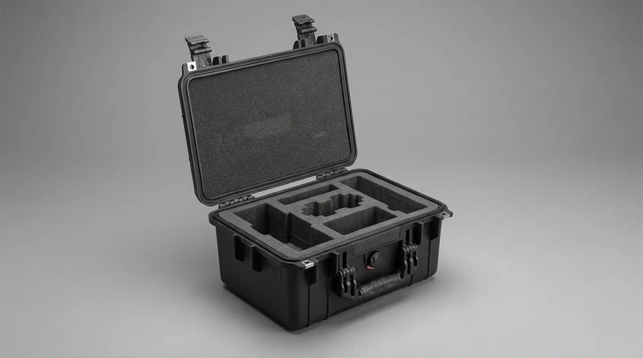
First, each sand mold needs its own cell and stacking is prohibited. A sand mold can carry its own weight, but only if the load is evenly distributed. With two molds stacked, the base of the upper mold presses on the cavity of the lower one, local pressure far exceeds the compressive strength of the sand, and the result is a collapsed cavity or a loose surface layer. The correct arrangement is one cell per mold, a flat cell floor, 1 mm to 2 mm clearance between cell wall and mold side, and cell depth at least 40 percent of mold height, so the mold cannot move horizontally and carries no additional vertical load.
Second, vibration is the hidden killer. Under sustained vibration a sand mold develops internal micro-cracks that are completely invisible on the surface. During pouring, the pressure of the liquid metal opens them into sand inclusion, burn-on or run-out defects. The buffer layer for a sand mold is therefore not a case of thicker is better; it must create soft contact plus rapid decay. Use an EVA 30D to 45D liner with 15 mm to 25 mm of buffer, and never let a hard material touch the sand directly.
Third, moisture control has to be proactive. Core and resin mold surfaces slowly absorb moisture, which lowers surface strength. The measures are a barrier film or bag around each mold or core, desiccant inside the case, a case that seals to IP65 or better, and a humidity indicator card so the condition can be judged on arrival. One point needs emphasis: desiccant can only control relative humidity inside the case; it cannot dry out a mold that has already absorbed moisture. Confirm before packing that the mold is at the dry condition specified by the process.
Fourth, cavity face protection. The cavity face, the surface that contacts liquid metal, must not be touched by any hard object and must not be contaminated by dust. Where a mold is shipped assembled with its core already in place, the destructive potential of transport vibration rises sharply. Use PU foam as local packing so that the core is also restrained inside the cavity.
Fifth, orientation marking. Sand molds must be marked this way up using the symbols defined in GB/T 191, and laying them on their side or upside down must be prohibited. In engineering practice, more than half of sand mold transit damage cases trace back to a mold being laid on its side during handling, which is a marking and work-practice issue rather than a case-strength issue.
3. Resin Sand, Sodium Silicate Sand and Green Sand: Different Shipping Behavior
Not all sand molds fear the same thing. Classified by binder system, the protection emphasis differs clearly.
Resin sand, whether no-bake or precoated, gets its strength from resin bridges. Compressive strength is relatively high, but sensitivity to humidity is also relatively high: absorbed moisture softens the resin film and lowers surface strength. Resin sand is also noticeably brittle, breaking away in blocks after corner impact. The protection emphasis is barrier packaging, individual cells and no stacked vibration.
Sodium silicate sand gets its strength from a sodium silicate gel. Its moisture absorption is stronger than resin sand, and after absorption the surface becomes damp, soft and even tacky. Sodium silicate sand carries the highest risk on long sea voyages. Use a three-part combination of barrier bag, desiccant and a case with a high sealing rating, with an adequate desiccant charge. A working reference is 100 g of silica gel per 50 L of internal volume, increased for longer transit and for humid climate zones.
Green sand relies on water and clay for bonding. Its water content is deliberately inside a process window, so the transport problem is drying out rather than taking on water. An over-dry case with aggressive desiccant makes the green sand surface brittle, and the mold then washes during pouring. Green sand molds should therefore not be shipped with strong desiccant. Use a seal-and-hold-moisture strategy instead: wrap in barrier film to block water exchange with outside air, add little or no desiccant, and keep transit and storage periods short. This is the exact opposite of the resin and silicate approach, and the two must be specified separately in the technical agreement.
Precoated sand shell cores are thin-walled and hollow. They are stiff but brittle and fear point loads and impact. Use PU foam with a contoured support pocket and eliminate every concentrated load point.
The table below compares protection requirements by sand type.
| Sand type | Strength source | Moisture behavior | Packaging strategy | Desiccant use | Main risk |
|---|---|---|---|---|---|
| --- | --- | --- | --- | --- | --- |
| Resin no-bake sand | Resin bridges | Softens when damp | Barrier bag plus individual cells | Moderate charge | Moisture pickup, corner loss |
| Precoated sand shell core | Resin film | Softens when damp | Contoured PU support plus barrier bag | Moderate charge | Fracture under point load |
| Sodium silicate sand | Silicate gel | Strong absorption, surface dampness | Barrier bag plus high-sealing case | Full charge | Surface softening, dimensional change |
| Green sand | Water plus clay | Dries out and becomes brittle | Sealed moisture retention, short cycle | Little or none | Surface drying, mold wash |
| Furan resin sand | Furan resin | Softens when damp | Barrier bag plus individual cells | Moderate charge | Moisture pickup, dimensional change |
4. Metal Dies and Die-Casting Dies: Cavity Face, Parting Line, Guide Pillars and Bushings
Metal dies and die-casting dies carry the weight in a casting tooling case and test the support structure hardest.
Cavity face. The cavity is the most precisely machined surface on the die, typically in the Ra 0.4 um to 1.6 um range. The rule is absolute: it touches nothing hard. Apply peelable protective film or a soft protective pad over the cavity, stand the die with the parting line up, and never let the cavity face downward contact the case floor.
Parting line. The parting line sets the closing gap and the flash allowance on the casting. Typical transit damage is edge impact and local indentation. Fit a rigid protective cover, in timber or plastic, over the parting line and fix that cover with the same fasteners that hold the die, so the cover cannot itself become a striking object.
Guide pillars and bushings. This is the pair most easily deformed on a die-casting or injection die. A guide pillar is a slender cylinder, and a lateral impact bends it; after assembly the symptom is increased closing resistance or loss of guidance. Remove guide pillars and bushings and pack them separately, or at minimum provide rigid support along the full pillar length. If they cannot be removed, guarantee that the die cannot move laterally inside the case.
Ejector pins, ejector plates and return mechanisms. Ejector pins are slender and numerous and bend easily. Store them in individual PE or PU cells, or wrap the whole set in soft material and restrain it in a dedicated zone. Ejector plates are flat parts where corner protection and distortion control matter.
Cooling and hydraulic fittings on die-casting dies. These are exposed fine-thread or quick-coupling features. Impact damages the thread or leaves a nick in the sealing face, producing a leak after installation. Fit caps or protective covers on all of them and blow out residual media before packing.
Mounting faces on large dies. The die base normally carries mounting slots or bolt holes, which are machined surfaces that indent under load. A rubber or polyurethane pad must sit between the timber skid and the die so that load transfers through area contact. For base structure design on heavy cases, see case foam material comparison.
5. Tool Steel Corrosion and Moisture Control: From Desiccant to VCI
Tool steel corrosion is a delayed failure. The unit passes outgoing inspection, rust spots appear on opening, and assigning responsibility becomes difficult. Rust prevention therefore deserves its own section in the technical agreement.
First, define the protection period. This runs from completion of packing to opening, commonly specified as 6, 12 or 24 months. The longer the period, the higher the required grade of packaging material and the sealing rating of the case. State the start point and the criterion: for example, the protection period runs from the packing completion date and no visible rust is permitted on the cavity face or parting line at opening. For material grade selection, refer to the approach in GB/T 4879 rust-preventive packaging.
Second, vapor corrosion inhibitor is the preferred route for dies. VCI film or paper releases an inhibiting vapor inside an enclosed space and forms a molecular layer on the metal surface, which suits complex cavity faces and deep pockets especially well. Four points govern its use: the VCI material must form a reasonably enclosed volume around the die, or the vapor concentration will be too low; VCI does not replace drying and must be combined with desiccant in long, humid shipments; copper and aluminum need a compatible VCI formulation because amine-based inhibitors attack copper alloys; and different metals sharing one sealed volume need physical separation to suppress galvanic corrosion.
Third, size the desiccant by volume. A common working figure is 100 g of silica gel per 50 L of internal case volume, adjusted upward by 1.5 to 2 times when transit exceeds 30 days, when the destination port is in a hot and humid climate zone, or when the case sealing rating is below IP65. Desiccant needs an enclosure to work in, so the sealing rating of the case is the precondition for any drying strategy. For the sealing requirements involved, see the IP67 protective case design.
Fourth, match any coating-type rust preventive to the downstream process. Some dies are cleaned before installation, and if the residual rust preventive is hard to remove it interferes with later coating or causes surface defects in castings. Require in the agreement that the rust-preventive material be fully removable with a specified cleaner within a stated time.
Fifth, avoid mixing dissimilar metals. Steel, aluminum and copper alloys sharing one sealed volume with condensation present will form galvanic couples. If mixing is unavoidable, separate the metals physically and strengthen the drying.
6. Heavy-Load Support Structures: Skids, Steel Frames and Contact Ratio
Most transit damage on large casting dies is not impact damage but load damage: local crushing and permanent distortion caused by uneven load distribution.
The support contact ratio is the first metric. The working requirement is at least 80 percent contact between the die base and the support face. Below that, load concentrates on a few protruding points, the timber support crushes, the die mounting face deforms plastically, and after installation the symptom is poor closing or uneven casting thickness. The way to raise the contact ratio is to cut a machinable liner, such as a CNC-profiled PE support, to the actual shape of the die base, rather than laying the die on a flat board and hoping it settles.
Selecting the base format. Base format falls into three bands by die weight:
| Die weight | Base format | Load-bearing member | Suitable transport | Notes |
|---|---|---|---|---|
| --- | --- | --- | --- | --- |
| 50-300 kg | Solid timber skid (plywood plus timber) | Timber longitudinal rails | Road, air | Forklift pocket height at least 90 mm |
| 300-1500 kg | Timber skid plus steel base rails | Channel or square tube plus timber | Road, LCL sea | Rubber pads between rail and die |
| 1500-5000 kg | Steel-timber composite frame | Welded steel frame plus timber deck | FCL sea, dedicated vehicle | Lift and tie-down points must be marked |
The division of labor between structure and cushion must be explicit. Structure carries the weight, cushioning absorbs impact, and the cut liner does the locating. Asking foam to carry weight and locate at the same time is the most common error in heavy cases. Foam creeps under sustained pressure, and after a few weeks the die has shifted and begins striking neighboring parts.
Where the tie-down points go. Straps and clamps should bear on mounting holes, lifting lugs or dedicated slots, never directly on the cavity face or parting line. Use at least four tie-down points arranged symmetrically so that the die cannot slide. For latch and clamp selection, see toolbox hinge, latch and seal selection.
7. Lifting and Handling: Lift Points, Center of Gravity and Overturning Risk
Handling is the highest-risk segment for casting dies, and the failures usually trace to external marking and work practice rather than to the case itself.
Lift points must be defined in advance. Large dies normally have lifting lugs or threaded lifting holes, but not all of them do. Where the die has none, the lifting plan must be settled at the packaging design stage, with the case marked for the permitted method, for example forklift from the base only, no top lifting.
Center of gravity marking. An eccentric die tilts during lifting, and the lateral force of that tilt slides the die inside the case. Mark the center of gravity in both the lateral and longitudinal directions on the outside of the case, and add a no-side-tilt symbol. For a strongly offset die, add lateral stops inside the case so the die physically cannot move sideways.
Working space for forklifts and cranes. Leave enough forklift pocket height at the base, at least 90 mm as a working figure, and chamfer or steel-edge the pocket entrance so repeated fork insertion does not split the skid deck. Once a forklift pocket is split, overall skid rigidity drops sharply and stacking load begins to reach the die.
Minimize handling events. Every extra transfer is another opportunity for a drop or a collision. For precision dies, use a direct one-case-through logistics plan and avoid transshipment unpacking. Where transshipment is unavoidable, ensure the intermediate warehouse offers cover from rain and sun.
Case self-weight must not become a liability. A steel-timber composite frame is strong but heavy and may need special equipment to move. If the customer site only has ordinary forklifts, prefer a lightened design rather than simply adding more material. For handling and mobility design on heavy cases, see protective case pressure equalization valve design, which also covers case structure and fittings.
8. Slides, Inserts and Cooling-Line Fittings: Separating Small and Large Items
Die attachments and small parts are numerous, valuable and easy to lose. They fall into the category of items that look unimportant but generate the largest losses.
Slides and core-pulling mechanisms. A slide normally mates with the die body through a T-slot or clamp plate, and the mating surfaces are precision features. If the slide moves within its slot in transit, the mating surfaces score. Remove slides and pack them separately with inhibitor paper between mating faces. If removal is impossible, fit a spacer block between slide and body so the slide cannot shift.
Inserts and cores. A clean, burr-free mating face and working face is the baseline requirement. Give each part its own cell, wrap in inhibitor paper or VCI film, and never allow several parts to rub against each other in one compartment.
Cooling fittings, quick couplers and hoses. The key actions are drain and cap. Blow out residual cooling water or hydraulic fluid before packing, cap every port, and prevent residual liquid from seeping out to contaminate the liner or corrode the fitting internally.
Bolts, pins and locating components. Locating pins and pin bores sit on the accuracy chain of the die. Package them as a set per die number and mark the die number on each bag. Mixed-up components cause mis-assembly that is far harder to trace than a broken part.
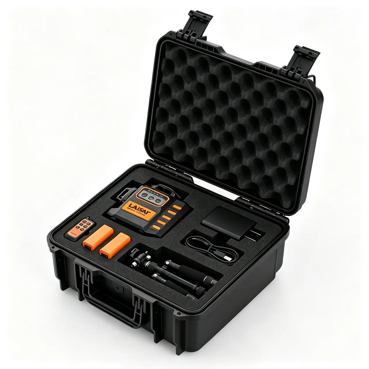
The zoning principle for small and large items. Large items and small items must be physically zoned inside the case with a solid partition between them. There are two reasons: small parts should not take load transmitted from large ones, and small parts should not be flung out to strike a cavity face when a large item takes an impact. For replaceable dividers and zoning design, see removable divider system design.
9. Flasks, Jackets and Gating Components: Controlling Distortion in Thin-Wall Parts
Flasks and jackets are everyday tooling in a foundry, and they are welded thin-wall structures with far less rigidity than they appear to have.
Stacking is the main source of flask distortion. A flask is typically a rectangular welded frame with wall thickness of 6 mm to 20 mm. Stacked flat three or four high, the middle unit's locating pin bores and pin seats take both lateral and vertical load, and long-term stacking changes the diagonal dimension. Stand them upright, fix each one individually in a PE cell or with timber dividers, and restrain lateral movement inside the case.
Locating pins and bushings. The locating pin is what aligns upper and lower flasks, and impact damage produces mold mismatch and casting shift. Fit protective sleeves, or remove the pins and pack them separately.
Pouring cups, sprue, runner and ceramic filters. These refractory ceramic parts are clearly brittle and fear point loads and impact. Use individual PU foam cells and rigid sleeves for slender pieces. Ceramic foam filters are especially prone to corner breakage, and the broken fragments enter the cavity directly as inclusion defects.
Plastic film used in vacuum and V-process molding. This consumable fears creasing and puncture. Coil it and restrain it in a dedicated zone away from hard items.
Chills and chill blocks. Chills are usually cast iron or copper, heavy with sharp corners. Their corrosion requirement outweighs their appearance requirement. Wrap in VCI film and zone them separately, never in the same compartment as a cavity face.
10. Oil and Liquid Separation: The Residual Boundary for Release Agents and Hydraulic Fluid
A die pulled from production almost always carries release agent, rust preventive, hydraulic fluid or cooling water. Unmanaged, these liquids cause three problems: they contaminate the liner and lower friction so that restraint fails, they soak into sand molds and reduce surface strength, and they form corrosive media that accelerate metal corrosion.
The standard sequence is drain, purge, cap, absorb.
- Drain: remove all media from hydraulic circuits, cooling circuits and air lines.
- Purge: blow the lines through with compressed air until no oil mist exits.
- Cap: fit caps or protective covers on every port.
- Absorb: lay replaceable absorbent pads in the wet zone of the case.
The wet and dry zones must be separated structurally, not by discipline. Build a dedicated liquid bay with absorbent pads inside and a solid partition between it and the dry zone. Even if a die still seeps slightly, the contamination stays local and never reaches sand molds or precision parts.
State the compliance boundary clearly. Release agents, hydraulic fluids and some cleaning agents are chemicals whose transport and storage fall under the applicable rules. A protective case provides mechanical protection and contamination isolation; it does not replace the packaging, marking and declaration requirements that apply to dangerous goods. For cross-border movements, follow the classification, packing and marking rules in ADR/IMDG hazmat transport case requirements, and state in the agreement that the case is not a chemical storage container.
Set a cleanability requirement for the liner. If the customer expects the liner to be cleanable, specify the cleaning method and the cleaner type in the agreement so that the cleaner and the liner material are chemically compatible. For maintenance practice, see how to clean a protective case.
11. Liners and Sealing: IP Ratings, Pressure Equalization and Desiccant Ratios
Liner material, sealing rating and drying strategy are three mutually supporting elements. Lose one and the whole protection scheme fails.
Liner material orientation. EVA is elastic, impact resistant and easy to machine, which suits small and medium dies and sand mold cells. PE cut foam has good dimensional stability and low-temperature behavior, which suits precision locating and slender parts. PU foam absorbs energy best, which suits sand cores and ceramic parts. EPP recovers well under repeated loading, which suits the base of heavy items. Timber and steel structural members carry the load. The selection order is: define the load-bearing structure first, then the locating material, then the cushioning material.
Using IP ratings correctly. IEC 60529 and GB/T 4208 define a enclosure's protection against solid foreign objects and water. For this class of case, IP65, meaning dust-tight and protected against water jets, is a reasonable starting point for road transport; IP67, adding temporary immersion, suits sea freight, open yards and rainy-season handling. An IP rating promises nothing about impact resistance, stacking strength or corrosion performance.
Pressure equalization is a necessary companion to a sealed case. A sealed case experiences temperature swings and altitude changes in transit, and the resulting differential repeatedly compresses the gasket, which over time can cause permanent set or seal failure. A watertight breather valve removes the differential while preserving the IP rating. For valve placement and selection, see pressure equalization valve design.
Desiccant ratio and humidity indication. Size the charge by internal volume, using the working figure of 100 g of silica gel per 50 L, adjusted upward for longer transit and humid climate zones, and place a humidity indicator card inside so the moisture question is answered the moment the case is opened. For cases containing green sand, switch to the seal-and-hold-moisture strategy, use little or no desiccant, and state this separately in the agreement.
12. Transport Verification and Standards Cross-Reference: ISTA, GB/T 4857 and ASTM D4169
The protection level of a mold case needs a citable test basis rather than an impression of sturdiness.
The ISTA series. ISTA Series 1 covers basic performance tests, Series 2 partial simulation and Series 3 general simulation. For mold cases, 2A for individual packages up to 68 kg and 3E for unitized loads over 68 kg moving as LTL freight are most often cited. For selection logic and test sequences, see the ISTA transport testing procedure.
The GB/T 4857 series. This series specifies basic test methods for transport packages, including drop, stacking, vibration, impact and water spray. Citing it in domestic contracts is often easier for third-party laboratories to execute. See GB/T 4857 transport packaging in practice.
ASTM D4169. This standard is organized around a distribution cycle and combines test sequences through a DC number. Its advantage is that severity can be tailored to the real logistics chain. See ASTM D4169 distribution cycle testing.
MIL-STD-810H. This standard provides environmental test methods for vibration, shock, temperature and humidity, and low pressure. State clearly that citing it means only that its test methods are used as a basis for environmental verification; it does not constitute military certification or a military qualification. See MIL-STD-810H environmental test basis.
A recommended test combination. For casting tooling cases, use four legs: vibration for long road and rail routes, drop or shock for handling, stacking for warehousing and container loading, and temperature-humidity cycling for sea freight and cross-climate routes. Sand mold cases deserve a separate loaded vibration test because their damage is cumulative. Mold cases should add a 48-hour stacking test to quantify how much the skid deforms under long-term load.
13. Acceptance, AQL Sampling and Volume Supply Collaboration
To convert these requirements into executable procurement actions, work through the following checklist.
Design confirmation stage:
- Confirm the die list, unit weights, envelope dimensions, center of gravity and lift points.
- Confirm the target support contact ratio and the support material, with CNC-profiled PE preferred.
- Confirm the zoning plan between sand molds and metal items, and the replaceability of wet-zone absorbent pads.
- Confirm the basis for the desiccant calculation and the number of humidity indicator cards.
- Confirm the case IP rating and pressure equalization valve configuration.
Sample verification stage:
- Check fit tolerances and the feel of insertion and removal for dies and sand molds.
- Run the agreed loaded vibration, drop and stacking sequence.
- Open a sand mold case and confirm no broken corners and no loose surface sand.
- Open a metal die case and confirm no rust spots and no indentations on cavity face and parting line.
Volume delivery stage:
- Build the AQL plan following the sampling logic of GB/T 2828.1, classifying defects as critical, major and minor. Critical defects such as seal failure, support fracture and broken assembled molds should be set at AQL 0. Major defects such as parting-line indentations, rust spots and out-of-tolerance liner cells generally fall between AQL 0.65 and 1.5. Minor defects such as cosmetic scratches and print misregistration generally fall between AQL 2.5 and 4.0. See custom case acceptance and AQL sampling.
- Randomly open cases each batch to check liner fit, fastener torque and humidity indicator status.
- Verify handling symbols under GB/T 191, IPPC marks on export skids and accompanying documents.
Volume supply and collaboration. Foundries and mold shops typically need liners matched to die models, cells sized to sand mold dimensions, and staged delivery against an annual framework. JUNZHJIA (Kexin New Materials (Guangdong) Co., Ltd.) provides CNC-cut liners to die drawings, matched seals and latches by model, and inspection documents covering IP rating and whole-case testing, and it accepts OEM/ODM and wholesale agency business. For customers shipping sand molds and dies together, a three-zone arrangement of metal zone, sand mold zone and attachment zone is available. For factory assessment and sampling workflow, see how to choose a protective case OEM factory.
Frequently Asked Questions
Q: Does a casting mold case have to reach IP67, or is IP65 sufficient?
A: It depends on the logistics route and the climate, not on a general preference for higher numbers. IP65 means dust-tight and protected against water jets, which suits road transport, covered storage and in-plant transfer, and it is the sensible starting point for most casting tooling cases. IP67 adds temporary immersion, typically tested at 1 m for 30 minutes, and suits sea freight with transshipment, open yards, rainy-season handling and cases that are washed down. Three questions settle it: is there a risk of open storage or short-term standing water; does the route include sea freight with its humidity and condensation cycles; and will the case be washed after arrival? One caution matters as much as the rating. An IP rating describes only protection against solids and water and promises nothing about impact resistance, stacking strength or corrosion performance. Even at IP67, the support structure, the contact ratio at the support face and the liner material still have to be specified separately. For sand molds, the rating only stops outside moisture from entering; it cannot replace individual barrier packaging for each mold. For metal dies, the rating only slows corrosion; it cannot replace VCI film and rust-preventive oil. Specify IP rating, desiccant charge and rust-preventive material grade as three separate clauses, each with its own acceptance criterion.
Q: Can sand molds and metal dies be shipped in the same case?
A: Yes, but only with strict physical zoning, otherwise the classic outcome is every die perfect and every sand mold scrap. A three-zone arrangement is the reliable approach: a metal zone, a sand mold zone and an attachment zone, separated by solid partitions. The metal zone is built around rigid support, with at least 80 percent contact between die base and support face, and rubber pads between skid and die so load transfers through area contact. The sand mold zone is built around individual cells, one mold per cell, a flat cell floor, 1 mm to 2 mm clearance between cell wall and mold side, and cell depth at least 40 percent of mold height, so the mold cannot move horizontally and carries no extra vertical load. The attachment zone holds slides, inserts and fittings, each in its own cell with inhibitor paper. Three further points matter. First, sand molds and metal parts must not share one piece of foam, because sustained pressure from the metal part makes the foam creep and the resulting movement eventually strikes the sand mold. Second, no sand mold should carry weight from any other item. Third, if a die carries oil or residual media, lay replaceable absorbent pads in a wet zone fully separated from the sand mold zone so oil cannot soak into the sand and reduce surface strength. JUNZHJIA can design the whole liner around this three-zone structure, making the boundaries physical rather than procedural.
Q: How do resin sand, sodium silicate sand and green sand differ in transport protection?
A: Their protection strategies point in clearly different directions, and one specification cannot cover all three. Resin sand gets its strength from resin bridges. Compressive strength is high, but humidity sensitivity is also high: absorbed moisture softens the resin film and lowers surface strength, and the material is brittle enough that corners break off in blocks after impact. The emphasis is barrier packaging, individual cells and no stacked vibration. Sodium silicate sand gets its strength from a silicate gel and absorbs moisture more strongly than resin sand, becoming damp, soft and even tacky on the surface. It carries the highest risk on long sea voyages, so use a three-part combination of barrier bag, adequate desiccant and a high-sealing case, with the desiccant charge increased above the working figure of 100 g of silica gel per 50 L of internal volume for longer routes and humid climate zones. Green sand is the opposite. It depends on water and clay for strength, its water content sits inside the process window, and the transport risk is drying out, not taking on water. Do not ship green sand with strong desiccant. Use a seal-and-hold-moisture strategy, wrapping in barrier film to block water exchange with outside air, adding little or no desiccant, and keeping transit and storage short. Mixing all three types under one drying scheme is a common error. List the packaging requirement by sand type in the technical agreement, and mark green sand cases as no desiccant or minimum desiccant.
Q: How should a large metal die be supported inside the case so it is not crushed?
A: Most damage to large dies is load damage rather than impact damage, meaning local crushing and permanent distortion from uneven load distribution. The central metric is the support contact ratio, with at least 80 percent as the working requirement. Below that, load concentrates on a few protruding points, the timber support crushes, the die mounting face deforms plastically, and after installation the symptoms are poor closing and uneven casting thickness. Raise the contact ratio by cutting a machinable support, such as a CNC-profiled PE block, to the actual shape of the die base rather than laying the die on a flat board. Select the base format by weight band: solid timber skid for 50 kg to 300 kg; timber skid with steel base rails between 300 kg and 1500 kg, with rubber pads between rail and die; and a steel-timber composite frame from 1500 kg to 5000 kg, with lift and tie-down points marked. One further principle is decisive: structure carries the weight, cushioning absorbs impact, and the cut liner does the locating. Never ask foam to carry weight and locate simultaneously, because foam creeps under sustained pressure and the die shifts within weeks. Use at least four tie-down points arranged symmetrically, bearing on mounting holes, lifting lugs or dedicated slots rather than on the cavity face or parting line. For eccentric dies, add lateral stops inside the case and mark the center of gravity on the outside.
Q: How should the rust protection period for tool steel be specified, and what does VCI require?
A: The protection period runs from packing completion to opening, commonly specified as 6, 12 or 24 months, and a longer period demands a higher grade of packaging material and a higher sealing rating on the case. State both start point and criterion in the contract: the period runs from the packing completion date, and no visible rust is permitted on the cavity face or parting line at opening. Vapor corrosion inhibitor film or paper is the preferred route for dies. It releases an inhibiting vapor inside an enclosed space and forms a molecular layer on the metal surface, which suits complex cavity faces and deep pockets well. Four points govern its use. First, the VCI material must form a reasonably enclosed volume around the die, or the vapor concentration will be too low and performance drops sharply. Second, VCI does not replace drying and must be combined with desiccant in long humid shipments, using 100 g of silica gel per 50 L of internal volume, increased 1.5 to 2 times for long sea routes or hot humid destinations. Third, copper and aluminum need a compatible VCI formulation because amine-based inhibitors corrode copper alloys, and mixed-metal shipments need physical separation to suppress galvanic corrosion. Fourth, any coating-type rust preventive must suit downstream processing, since residue that is hard to remove interferes with later coating or causes casting surface defects; specify a cleanability requirement. Finally, place a humidity indicator card in every case so a moisture dispute becomes verifiable.
Q: How should release agent and hydraulic fluid residue be handled, and can the case serve as a chemical container?
A: A die removed from production almost always carries release agent, rust preventive, hydraulic fluid or cooling water, and unmanaged liquids cause three consequences: they contaminate the liner and lower friction so restraint fails, they soak into sand molds and reduce surface strength, and they form corrosive media that accelerate metal corrosion. Run a four-step standard sequence. First, drain all media from hydraulic circuits, cooling circuits and air lines. Second, purge the lines with compressed air until no oil mist exits. Third, cap every port to prevent seepage in transit. Fourth, lay replaceable absorbent pads in the wet zone of the case. Structurally, build a dedicated liquid bay with absorbent pads inside and a solid partition between bay and dry zone, so contamination stays local rather than depending on operator discipline. The compliance boundary needs to be stated plainly: release agents, hydraulic fluids and some cleaning agents are chemicals whose transport and storage fall under the applicable rules. A protective case provides mechanical protection and contamination isolation and does not replace the packaging, marking and declaration requirements that apply to dangerous goods. For cross-border movements, follow the classification and marking rules in the ADR and IMDG frameworks. State in the procurement agreement that the case is not used as a chemical or hazardous waste storage container, and specify the permitted cleaning method and cleaner type so that cleaner chemistry and liner material remain compatible.
Q: How should thin-wall items such as flasks and jackets be packed so they do not distort?
A: Flasks and jackets are welded thin-wall structures with far less rigidity than they appear to have, typically with wall thickness between 6 mm and 20 mm, and stacking rather than impact is the main source of distortion. Stacked flat three or four high, the middle unit's locating pin bores and pin seats take both lateral and vertical load at the same time, and long-term stacking changes the diagonal dimension, which shows up on site as mold mismatch during closing. The correct approach is to stand them upright, fix each one individually in a PE cell or with timber dividers, and restrain lateral movement inside the case so that load transfers through the flask wall plane rather than through the pin seats. Locating pins and bushings are the alignment features that mate upper and lower flasks, and impact damage leads directly to mismatch and casting shift, so fit protective sleeves or remove the pins and pack them separately. Where a flask carries gating ceramics such as a pouring cup or sprue, treat them as independent fragile items: individual PU foam cells, rigid sleeves on slender parts, and no sharing compartments with steel items. Ceramic foam filters are especially prone to corner breakage, and broken fragments enter the cavity directly as inclusion defects, so each needs its own packaging. On verification, add a 48-hour stacking test to flask cases and measure the diagonal change of the middle unit directly, so the technical agreement carries a quantified criterion instead of a subjective judgment.
Q: How should a batch of casting mold cases be accepted, and how should AQL sampling be structured?
A: Accept in three stages and set decision rules following the sampling logic of GB/T 2828.1. Stage one is arrival inspection and document check: verify handling symbols, IPPC marks on export skids, packing list and die numbers against each other; inspect for through-cracks, distortion and detached gaskets; open cases to look for dusting, oil contamination and crushed liner. Stage two is functional checking: spot-check that pressure equalization valves breathe freely; sample hinge and latch operating force and end stops; check fastener torque on skid and base rail joints on heavy cases; and read the humidity indicator cards to confirm whether moisture exposure has occurred. Stage three is test verification: run the agreed loaded vibration, drop or shock and stacking sequence, give sand mold cases their own loaded vibration test because their damage is cumulative, and add a 48-hour stacking test on die cases to quantify skid deformation. For the AQL plan, classify defects into three groups. Critical defects such as seal failure, support fracture and broken assembled molds should be set at AQL 0. Major defects such as parting-line indentations, cavity-face rust spots, out-of-tolerance liner cells and latch failure generally fall between AQL 0.65 and 1.5. Minor defects such as cosmetic scratches, print misregistration and slightly unclear marking generally fall between AQL 2.5 and 4.0. Determine sample size from lot size at general inspection level II. Keep opening photographs and test records from each batch as the basis for later traceability and responsibility allocation.
Conclusion & Related Reading
The design logic of a casting mold case comes down to three zones, two controls and one verification. Three zones are the metal zone, the sand mold zone and the attachment zone, separated by solid partitions so that weight, brittleness and oil contamination are handled independently. Two controls are humidity and movement: humidity is solved by the combination of sealing rating, barrier packaging and desiccant charge, while movement is solved by contoured supports, tie-down points and lateral stops working together. One verification is a vibration, drop, stacking and temperature-humidity test sequence tailored to the real logistics chain, replacing judgment by feel with measured data. Sand molds and metal dies sharing one route does not mean they can share one protection scheme. Treating them separately is in fact the cheaper approach.
For buyers, the three items most worth writing into the technical agreement are the support contact ratio target, the zoning and moisture scheme for sand molds, and the opening inspection criteria on arrival. For foundries and mold shops, standardizing liners by die model and generalizing sand mold cells by mold size is the most direct way to reduce tooling allocation cost. JUNZHJIA supports liners cut to drawings, seals matched by model, and inspection documents covering IP rating and whole-case testing, and it accepts OEM/ODM and wholesale agency collaboration. Bring your die list and logistics route and we can work through the specification together.
Related Reading