

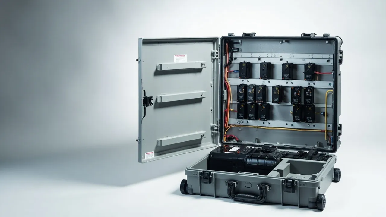
The main enemy of a power distribution cabinet component shipment is not breakage. It is quiet deformation. A copper busbar 1.2 metres long that bows by two millimetres in transit can arrive with a mating face that no longer seats properly, so that even a correctly torqued bolt leaves a gap, contact resistance climbs and the joint runs hot. A moulded case circuit breaker squeezed sideways inside a case can lose the mechanism stroke and trip point it was set to at the factory, and a calibration bench will not necessarily reveal the change, which then shows up in service as nuisance tripping or a refusal to trip. Busbars and breakers both belong to the class of parts that look perfect and perform differently.
This article is for switchboard builders, distribution cabinet integrators, electrical installation contractors and equipment buyers. It works through deformation control, insulation and short-circuit prevention, moisture protection and post-delivery re-measurement for breakers, busbars, withdrawable units, secondary wiring and instruments. It also explains how JUNZHJIA supports custom packaging and supply for switchboard components. Standards referenced here serve as a technical index; governing figures come from the project technical agreement and the version of each standard in force.
Contents
- Why deformation leads the agenda for switchboard parts
- Breaker components: mechanism, contacts and trip units
- Busbars and connectors: flatness, plating and bend radius
- Withdrawable and functional units: structural restraint
- Secondary wiring, terminals and instruments
- Three deformation controls: support, compartment, conformance
- Insulation and short-circuit prevention, from creepage to static bleed
- Moisture control and metal surface protection
- Materials: enclosure, liner and divider
- Ingress protection and environmental testing
- Lifting, stacking and transport orientation
- Re-measurement on arrival: flatness, insulation, appearance
- Custom engineering and switchboard builder supply support
- FAQ
- Conclusion and further reading
Why deformation leads the agenda for switchboard parts
The value of distribution cabinet components lies in fit, not in whether they can conduct at all. A busbar conducts through face contact, a breaker acts through mechanism stroke, a withdrawable unit locates through rails and plug contacts, and an instrument fits through a cut-out and panel interface. Once transport stress moves any of those interfaces, the part is undamaged in the ordinary sense yet can no longer be assembled or operated as designed. The first metric for switchboard component packaging is therefore dimensional change, and breakage rate comes second.
Generic packaging absorbs impact with cushioning but does not limit movement or sustained load. Foam held under compression keeps transferring load to the part over time. Where clearance exists between liner and part, the part repeatedly strikes the liner under vibration and accumulates fatigue. Stacking load travels down the walls into the contents and produces sustained bending. All three mechanisms cause deformation and none of them announces itself at the moment the case is opened.
The right sequence is restraint and support first, cushioning second, sealing and moisture control last. Restraint answers whether the part can move, support answers where the load goes, and cushioning answers how impact energy is absorbed. Reverse the sequence and the result is a case that survives a drop while the busbar comes out bowed. Where a project also covers switchgear or transformer parts, the two requirement sets can be reviewed together, as described for substation equipment cases.
Breaker components: mechanism, contacts and trip units
A circuit breaker is the key switching element of the cabinet, and its transport protection divides into three areas.
Operating mechanism and stored-energy springs. Closing and opening in moulded case and air circuit breakers depends on linkages and a stored-energy spring with a precise stroke. Repeated lateral squeezing or a drop in transit can plastically deform a linkage or change spring preload. Require the manufacturer to state the transport condition, whether closed, open or with energy released, enforce it, record it on the packing sheet, and verify against that record on arrival.
Contacts and arc chutes. Contact pressure is set by the mechanism, and arc chute plates are thin and easily deformed or displaced by impact. Prevent direct edge impact and add local cushioning blocks at exposed corners where necessary.
Trip units and electronic accessories. Electronic trip units contain circuit boards and sensors and are static sensitive. Use a dissipative liner with controlled surface resistance, sleeve exposed connectors, and provide a grounding tab inside the case. Where a project requires it, structure the packing and unpacking work instruction around ANSI/ESD S20.20; selection guidance is in ESD shielding cases. General technical requirements for low-voltage switchgear and controlgear may reference the GB/T 14048 series, in the version in force.
| Breaker component | Transport sensitivity | Packaging measure | Arrival check |
|---|---|---|---|
| --- | --- | --- | --- |
| Operating mechanism | Linkage deformation, changed energy state | Lock to specified state and record | State matches record |
| Contacts and arc chute | Plate deformation, changed contact pressure | Edge cushioning, no stacking load | Intact, free of binding |
| Electronic trip unit | Static damage, connector tension | Dissipative packing, terminal sleeves | No deformation or debris |
| Accessories and spares | Crushing in mixed packing, loss | Separate compartments, itemised list | Count matches list |
Busbars and connectors: flatness, plating and bend radius
A busbar is the component most sensitive to bending and the one that best reveals the technical level of a packaging design.
Flatness. The flatness of a mating face sets contact resistance directly. If a busbar is supported only at its ends, loaded locally, or pressed by another item, flatness drifts out of tolerance. The design requirement is continuous support along the full length plus multiple restraint points, never two blocks with a free span between them.
Plating. Copper bars are commonly tin, silver or nickel plated, and aluminium bars are supplied plain or tinned. A scratch through the plating creates a local corrosion site in humid air and a future contact resistance fault. Keep metal tools, fasteners and hard particles out of the case, and use a non-shedding closed-cell liner.
Bend radius. Formed bends are stress concentration zones. A reverse load in transit can cause spring-back or microcracking. The packaging should leave the bend in its natural state, neither flattened nor straightened.
Heat-shrink sleeving. Sleeved busbars suffer the same scratch risk as bare ones, and damage to the sleeve destroys the insulation function. Treat sleeved bars with the same separation as bare conductors.
| Busbar protection point | Risk | Design requirement | Verification |
|---|---|---|---|
| --- | --- | --- | --- |
| Flatness | Span deflection under load | Continuous support, multi-point restraint | Straight edge or surface plate |
| Plating | Local corrosion after scratching | Closed-cell liner, no metal debris | Visual plus wipe |
| Bend section | Spring-back or cracking | No load at the bend, natural state | Visual plus angle check |
| Shrink sleeve | Abrasion damage | Separate compartment, protective sleeve | Visual |
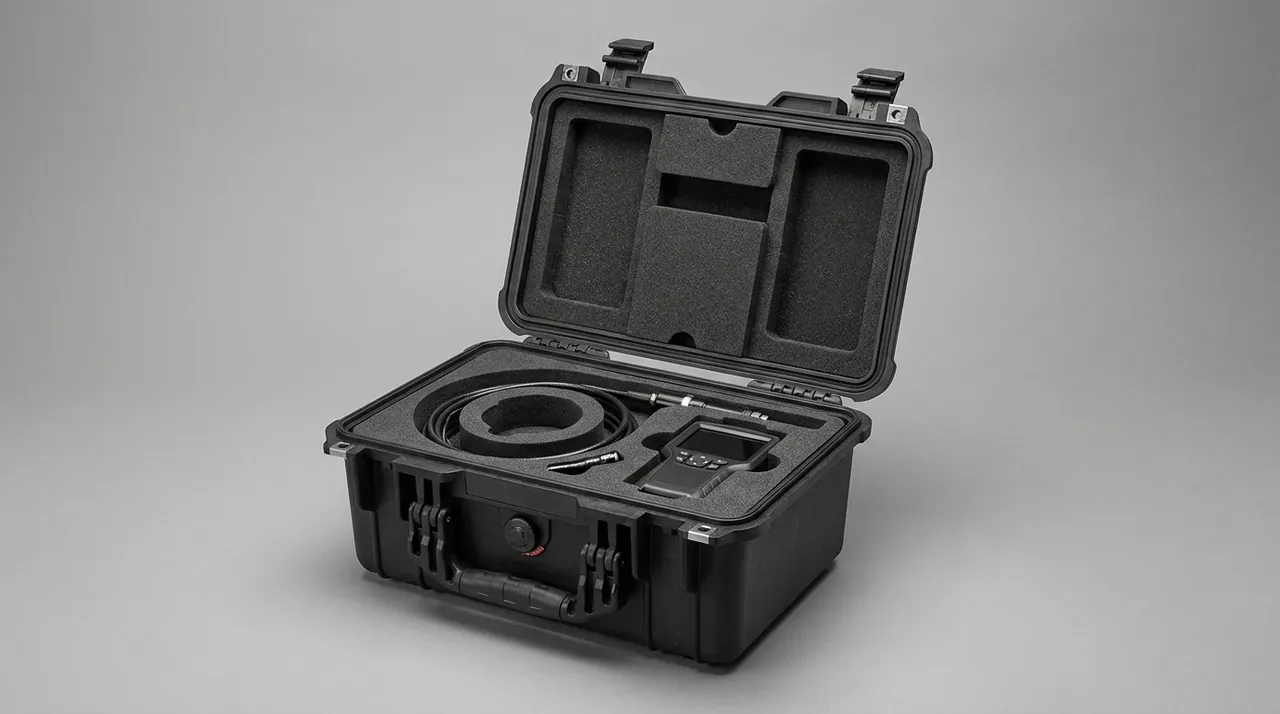
Where a cabinet ships with busbars in several segments, compartment them by segment number and include an assembly diagram to cut the time spent matching parts on site. Liner material choice follows the comparison set out in foam material comparison.
Withdrawable and functional units: structural restraint
A withdrawable functional unit combines rails, plug contacts and mechanical interlocks, making it a high-precision assembly whose main transport risk is misalignment.
Rails and slideways. Plug engagement depends on rail location accuracy. If a unit slides part-way out or takes a lateral shock, the rails can deform. Secure the unit in the fully inserted or fully withdrawn position as specified, and confirm whether transport fixings are required.
Plug contacts and busbar interfaces. The moving contact fingers align with the fixed contacts in the cabinet. If the unit shifts inside its case, fingers bend. Use compartmentalised construction so each unit sits in its own cavity with a rigid divider between cavities.
Mechanical interlocks. Interlocks contain springs and limit stops, and sustained load in transit can alter their operating characteristics. Support the interlock area so it never carries the weight of the unit itself.
Mixed shipments. When several units travel in one case, allocate a compartment per functional unit and print a location diagram inside the lid. For units that look alike but are not interchangeable, the diagram plus colour coding sharply reduces mis-installation. Reconfigurable partitioning logic is described in removable divider systems.
Secondary wiring, terminals and instruments
The secondary circuit is the nervous system of the cabinet. It is small in volume but expensive to rework.
Secondary harnesses. The typical failures are terminal tension and broken strands. Coil harnesses to the minimum bend radius stated by the manufacturer, secure them with non-conductive ties, and ensure they carry no tension at all. Cap the plugs and stow them in their own compartment.
Terminals and terminal blocks. Terminal blocks crack under crushing and must be stored away from busbars so heavier items cannot press on them. Screw terminals can loosen in transit, so plan to re-torque and confirm torque values on arrival according to the process specification.
Instruments and display units. Instruments typically have glass or LCD faces, so they are both fragile and scratch sensitive. Use a conforming liner and apply a surface protection film. Selection logic is covered in the instrument case selection guide.
Marking items. Nameplates, labels and rating plates rub off or lift at the edges in transit. Pack them separately and apply them at the correct assembly stage rather than at dispatch.
Three deformation controls: support, compartment, conformance
Reducing the earlier requirements to a reusable method gives three controls.
Support carries load along the intended path. Busbars need full-length support, heavy items must sit on the case floor or a rigid layer, and no part should ever carry load as a cantilever or across a free span. Support faces should be face contact rather than point contact to avoid local impressions.
Compartment separates items by stiffness, weight and risk. Heavy from light, metal from brittle, conductor from insulation. Compartmentalising simultaneously solves crushing, short circuits and contamination.
Conformance means a moulded liner shaped to the part so that contact is over an area rather than at discrete blocks. A conforming liner holds displacement to within a few millimetres, which no generic block can match. For mixed sizes, combine a common base layer with model-specific functional layers to control cost.
| Control | Problem solved | Typical implementation | Consequence if missed |
|---|---|---|---|
| --- | --- | --- | --- |
| Support | Deflection and local impressions | Full-length continuous support, rigid base | Busbar flatness out of tolerance |
| Compartment | Crushing, short circuits, contamination | Separate cavities with rigid dividers | Parts collide, plating scratched |
| Conformance | Displacement and secondary impact | Moulded liner, area contact | Repeated impact, fatigue deformation |
Insulation and short-circuit prevention, from creepage to static bleed
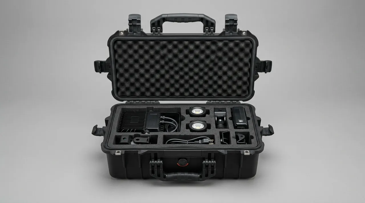
Insulation requirements for switchboard components operate on two levels: preserving the insulation of the parts themselves, and ensuring the packaging does not introduce a new conductive path.
Holding creepage and clearance. The separation between insulating supports, barriers and busbars is a design value. If an insulating part shifts in transit, the gap can close. Restrain insulating parts and confirm critical gaps dimensionally or visually on arrival.
Eliminating conductive paths. No loose metal may exist inside the case. Fasteners, washers and tools go into separate bags fixed in a non-conductor zone. Metal ties, metallised labels and metal-fibre cushioning materials are excluded.
Static bleed. Secondary devices and electronic instruments are static sensitive. A dissipative liner with a grounding tab creates a slow bleed path. It is worth separating two different approaches: shielding packaging uses a metal layer to block external fields but can become a conductor once damaged, while dissipative packaging relies on controlled surface resistance to release charge slowly and is the better fit for switchboard packaging that contains conductors.
Baseline for dielectric and insulation measurements. Bind the insulation resistance data taken at dispatch to the case serial number and compare it with the value measured on arrival. That both detects any moisture-related drop and isolates the transport contribution. Whether a case should be dust and water resistant at all is discussed in choosing an IP rating for a waterproof case.
Moisture control and metal surface protection
The metal surfaces in a distribution cabinet are mostly copper, aluminium, tin plated and zinc plated, and all of them oxidise, white-rust or spot-corrode once moisture is present. Moisture control and surface protection should be planned together.
Control the packing humidity. Pack in a low-humidity area wherever possible and dry the liner. If a part carries moisture from cleaning or machining, dry the surface first.
Provide humidity indication. Place a humidity indicator card or an electronic logger inside the case, read it on arrival and file the result. This single step converts moisture control from an intention into evidence and is one of the most common acceptance requirements on projects.
Size the desiccant correctly. Estimate from the free volume inside the case and the transit period, fix it away from metal parts, and confirm it produces no dust. If the case has a pressure balance element or a breathable membrane, increase the quantity accordingly.
Avoid acidic materials. Paper and timber fillers can release acidic vapour, which is unfriendly to copper and tin plated surfaces. Where they are used, specify a neutral acid-free grade and add a barrier film.
Dedicated protection for plated faces. For silver and tin plated busbars, apply a peelable protective film to mating faces and remove it on arrival. Confirm the film leaves no residue and does not outgas.
Materials: enclosure, liner and divider
| Location | Candidate materials | Selection driver | To avoid |
|---|---|---|---|
| --- | --- | --- | --- |
| Enclosure | Sealed polymer case, rotomoulded case, metal frame case | Strength, sealing, number of trips | Metal cases without internal insulation |
| Load-bearing liner | XPE, EPP | Compression set, load capacity | Materials with too much rebound |
| Conforming liner | Moulded EVA | No shedding, dimensional accuracy | Soft materials with migratory additives |
| Compartment divider | Phenolic board, epoxy board, rigid polymer sheet | Stiffness and insulation | Brittle or burred materials |
| Surface protection | Peelable protective film | No residue, no outgassing | Adhesive films with solvent residue |
Decide in this order: whether the material sheds, outgasses or conducts; then load capacity and cushioning; then cost and achievable trip count. For switchboard builders with circulating packaging, treat the liner as a consumable replaced by batch and design the shell for a multi-year life. The amortisation approach is set out in custom case mould cost analysis.
One further parameter is worth recording: the liner's compression set after the expected number of trips, rather than at first use. A material that feels firm when new can flatten by several millimetres after a dozen lifts, and once it flattens the restraint disappears and the deformation risk returns. Ask for a compression set figure at the relevant load and duration, and plan a liner replacement interval instead of waiting for visible damage.
Ingress protection and environmental testing
Ingress protection is defined in IEC 60529, mirrored by GB/T 4208, with the two digits covering solid objects and liquids. Grade selection for switchboard component cases follows the mode of carriage, the storage condition and the moisture package.
| Transport stage | Suggested grade | Moisture provision | Structural provision |
|---|---|---|---|
| --- | --- | --- | --- |
| In-plant transfer | Around IP54 | Indicator card | Scratch-resistant liner |
| Long-haul road | IP55 to IP65 | Desiccant plus indicator card | Rigid base and compartments |
| Export by sea | IP65 to IP67 | High-capacity desiccant or nitrogen | Salt mist protection, pressure balance |
| Site staging | IP66 to IP67 | Data logger | UV stabilised, condensation control |
Validation follows the carriage mode. Choose the programme that matches the actual channel from the ISTA sequence library, or assemble a bespoke cycle with ASTM D4169 delivery simulation. Projects delivered inside China commonly work to GB/T 4857 package test methods, which also covers stacking and drop items. Recommended acceptance points for switchboard parts include busbar flatness within tolerance, no fresh scratches in plating, uncompressed insulation gaps, smooth unit travel and no loosened fasteners. Where MIL-STD-810H methods are used, the report must state that the standard serves as an environmental test-method reference only and confers no military certification.
Lifting, stacking and transport orientation
Switchboard component cases tend to be large with the mass concentrated low, and handling is where deformation most often starts.
Lifting and forklift access. Mark lifting points, forklift positions and the centre of gravity. For off-centre loads the centre of gravity marking must be accurate, because any tilt during the lift introduces lateral bending.
Stacking limits. Determine stack height by test. Cases containing busbars are best not stacked at all; where stacking is unavoidable, add a rigid divider and place heavier cases at the bottom. Sustained stacking pressure permanently deforms the liner and destroys its restraining function.
Orientation. State the transport orientation for busbars and cabinet bodies and fit tilt indicators on two adjacent faces. Photograph before opening.
Handling frequency. Each transfer adds to cumulative impact. Prefer direct routes where possible, or use a reinforced base designed for repeated lifting.
People and tools. Use insulated tools for unpacking and keep the area free of metal swarf. Move busbars on a purpose-made carrier; never drag one or leave the middle unsupported.
Pallet and base design. The base is the interface between the case and every lift, so it deserves the same attention as the liner. A base that flexes too much lets the shell twist during a two-point lift and passes that twist straight to the busbars inside. Specify a base whose deflection under the rated load is known, cut fork pockets at the marked positions, and fit replaceable skids where the base meets the ground. On very long cases, confirm that the lifting points sit inside the footprint of the contents rather than beyond it, because a lift taken outside the centre of gravity rotates the load and can bow a busbar that is supported correctly in every other respect.
Re-measurement on arrival: flatness, insulation, appearance
Re-measurement on arrival is the only way to turn a deformation control from a design claim into a fact. Work through this sequence.
- Outer case and markings: record damage, tilt and impact indicator status and document completeness, with photographs.
- Acclimatisation: set standing time from the temperature differential so condensation does not form on cold parts.
- Immediate readings: read the humidity card or logger before any unpacking work.
- Busbar re-measurement: check flatness and mounting hole spacing on key bars to the drawing, and inspect plating and bend sections.
- Breaker inspection: verify the transport state record, operate the mechanism once by hand to confirm free movement, and inspect terminals and appearance.
- Withdrawable unit and mechanism check: confirm smooth unit travel, undistorted contact fingers and correct interlock action.
- Insulation re-measurement: measure insulation resistance and record ambient temperature and humidity, adding a dielectric test where the procedure requires.
- Filing: build one traceable record from case serial number, component numbers, readings and re-measurement data.
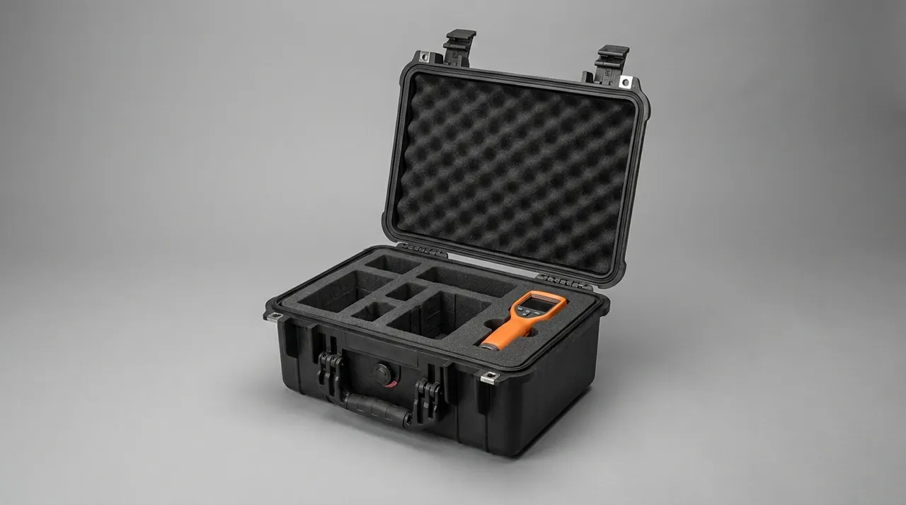
Step four deserves emphasis. Busbar flatness is best checked after acclimatisation and before assembly, while the bar is still in a free state, because only then does the reading reflect what transport actually did. Discover a poor mating face after assembly and the question of responsibility becomes far harder to settle.
Custom engineering and switchboard builder supply support
Switchboard builders face a familiar packaging problem: many models, small batches, tight delivery windows and a strong reuse requirement. Generality in the design therefore matters more than the cost of a single order. Taking distribution cabinet breaker and busbar cases as the example, the enclosures are produced by Kexin New Materials (Guangdong) Co., Ltd., which supplies cabinet manufacturers directly in volume, also serves the market through agents and export channels, develops OEM/ODM solutions from drawings or samples, and can issue material declarations and inspection documents with each batch under contract. The most useful custom capability for a switchboard builder is rigid support plus conforming compartments built around busbar length and bus system layout, because that single design decision addresses deformation and short circuits at the same time.
For a quotation, provide the component list with individual weights, busbar lengths and bend geometry, breaker models and transport state requirements, withdrawable unit dimensions and quantities, mode of carriage and stacking limits, insulation and static requirements, and the documents needed. Where specifications change often, an adjustable restraint scheme with a common base layer keeps the model-specific content to a minimum. Shortlisting a supplier starts with the checklist in selecting a protective case OEM, while incoming lots for export orders follow acceptance sampling under AQL.
FAQ
Q: Why is bubble wrap alone not enough for a busbar?
A: Bubble wrap addresses surface impact and nothing else, and the dominant failure of a busbar is bending. Two mechanisms matter: deflection caused by inadequate support, and sustained bending moment from stacking or squeezing. Bubble wrap is soft, has no fixed geometry, and lets the bar move. If the middle of the bar is unsupported after packing, vehicle vibration flexes it repeatedly; if something heavy is stacked on top, the film cannot carry the load and the pressure passes straight through to the copper. The correct approach is continuous support along the full length, multiple restraint points, and a rigid divider above to carry stacking load. Bubble wrap can be used for local surface protection, but it should never be the primary support structure or a substitute for compartments and a rigid base. It also helps to check for twist rather than bow alone, since a twisted bar seats badly even when its flatness reading looks acceptable.
Q: Should a circuit breaker be shipped closed or open?
A: Follow the breaker manufacturer's explicit requirement rather than site habit. Products differ: some specify open with energy released, some permit closed transport, and some require a dedicated transport fixing or lock. What matters is that the state is written down and that packing and arrival checks revolve around it. If the state is wrong, the stored-energy spring and linkage can sit in a non-design load condition during transport and the stroke can change. Record the transport state and the list of transport fixings on the packing sheet, verify them item by item on arrival, and operate the mechanism by hand during re-measurement to confirm free movement and no unusual noise. If the manufacturer is silent on the point, treat it as a question to settle before dispatch rather than a detail to decide on the loading dock. Asking for the transport condition in writing is a small request that removes a large source of uncertainty from any later warranty discussion.
Q: How should screws and tools be packed inside the case?
A: Bag them separately and fix them in a non-conductive zone. Never let them share a cavity with busbars, breakers or conductors. Two reasons drive this. Metal items rolling in transit scratch plating, dent enclosures and can jam a breaker mechanism. And loose metal near energised parts represents a possible bridging path, which is simply not acceptable in switchboard packaging. Fix bagged items inside the lid or in a dedicated accessory compartment using non-conductive ties and list them individually on the packing sheet. During arrival checks, count the accessories first and then take out components, so nothing is left behind inside a cavity. A useful habit is to keep the accessory bag attached to the packing list inside the lid so that counting and picking happen together. Accessories loose in a pocket or a separate carton are the ones most often lost, and a missing transport fixing is usually discovered only when the unit is being installed.
Q: How can I tell whether a busbar deformed in transit?
A: Use three checks together. First, appearance and impression marks: look for local dents, scratches and contact marks that do not match the liner support positions. Second, dimensional re-measurement: check flatness and hole spacing on critical sections against the drawing on a surface plate or with a straight edge, after acclimatisation and before assembly, otherwise assembly stress biases the result. Third, trial fitting: seat the mating faces and confirm no visible gap. Combined, these are far more reliable than appearance alone. If deformation is found, first establish whether it originated in transport or manufacture, then decide between straightening and replacement; on-site straightening is not recommended. If the bar has to be measured on site, choose a surface that is flat to a known standard and support the bar at its design points during the check, otherwise the reading describes the surface it rests on rather than the bar. Record ambient temperature as well.
Q: What is special about packing secondary harnesses and terminals?
A: Three points. First, bend radius: coil the harness to the minimum radius stated by the manufacturer, because forced tight bends damage conductors quickly and later show up as poor contact. Second, tension: a plug must never carry tension, so secure the harness body rather than the connector and cap every plug. Third, separation: store harnesses away from metal parts, busbars and fasteners so they cannot be crushed or abraded. Because secondary circuits are exposed low-voltage wiring, treat harnesses together with electronic instruments as static-sensitive items, using dissipative packaging and keeping a grounding provision in the unpacking area. Where harnesses leave the case for any reason, cap them again before the case is closed. An uncapped connector collects dust, and on a secondary circuit that will later be energised, dust is a slow and entirely avoidable risk. The same rule applies to spare parts shipped alongside the main assembly. If the cabinet layout has changed since the last shipment, label both ends of each harness before packing, because relabelling on site is a common source of wiring errors.
Q: How should the ingress protection grade be chosen?
A: From the mode of carriage and the storage condition, not by defaulting to the highest grade. In-plant transfer and short road journeys need dust protection primarily, so around IP54 is usually sufficient. Long-haul road transport suggests IP55 to IP65 with desiccant and a humidity indicator. Export by sea or cross-border intermodal transport suggests IP65 to IP67 plus salt mist protection, pressure balance and possibly a nitrogen blanket. Outdoor staging at site adds UV and condensation considerations. Note that the tighter the seal, the more internal pressure responds to temperature and altitude, so a pressure equalisation element is mandatory; without it the seals see repeated stress and fail earlier than expected. If a project spans several climates, set the grade from the most demanding leg of the route rather than from the origin or the destination alone. A case that is adequate for a domestic delivery can become entirely unsuitable once a short sea crossing is added.
Q: Do withdrawable units need dedicated transport fixings?
A: In most cases yes, with the cabinet manufacturer's requirement taking precedence. A unit locates through rails and plug contacts, so if it moves part-way in transit the fingers and fixed contacts can press against each other and deform, and the rails can shift under lateral shock. The usual approaches are to secure the unit in the fully inserted position, in the fully withdrawn position, or with a dedicated transport fixing that locks it in a specified state. Whichever is chosen must be written on the packing record and verified on arrival. If transport fixings ship with the case, store them in the accessory compartment and count them. Where a unit has shipped many times in the same case, check the fixing and the rail alignment as well as the unit. Repeated restraint in one position leaves a permanent set in the liner, so a fixing that worked on the first trip may no longer hold the unit correctly by the fifth.
Q: How can mixed-model shipments balance restraint quality against cost?
A: Layer the design and make part of it adjustable. The first layer is a common base that carries load and gives overall support, shared across a family of cases. The second layer is a model-specific functional layer shaped to busbar length, breaker model or unit size, at far lower cost than a complete mould. The third layer is adjustable hardware, such as movable dividers, locating posts or grid inserts, covering near-identical variants. Together they hold restraint accuracy while avoiding a separate tool for every model. The precondition is a clear component list and size distribution at the start, otherwise generality is bought at the expense of restraint. Whatever scheme is adopted, document the mapping between variants and functional layers. Without that mapping an adjustable design gradually turns into an improvised one, and improvised packaging is exactly where deformation risk returns. Review the mapping whenever a new model is introduced and retire layers that match nothing in the current range.
Conclusion and further reading
The decisive factor in switchboard component packaging is deformation that nobody sees. Continuous full-length support, compartments split by stiffness, and a conforming liner that holds parts to millimetre accuracy, followed by flatness re-measurement on arrival, are what keep transport-induced fit errors within an acceptable range. Starting with the next switchboard project, write busbar flatness re-measurement into the material receiving procedure and judge packaging by data rather than by feel.
Further reading