

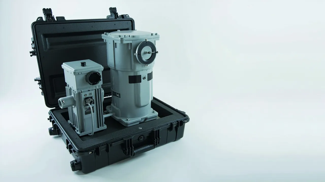
When primary equipment components for a substation travel between sites, the damage that matters is rarely the obvious crack. It is moisture ingress and invisible vibration damage. A transformer bushing whose porcelain is not visibly broken may still carry a microcrack introduced by an over-limit bending stress in transit, and that flaw only develops into a surface flashover once the unit is energised in rain or polluted air. A set of switchgear contacts left for weeks in a damp case can build an oxide film thick enough to push contact resistance out of specification. Neither failure raises an alarm at unpacking; both surface at the handover test.
This article is for substation EPC contractors, switchgear builders, transformer manufacturers and utility material and maintenance teams. It sets out the packaging control points for switchgear and transformer components, covering moisture control, vibration resistance, brittle part restraint, insulation state retention and goods-in acceptance, and it explains how JUNZHJIA supplies custom packaging for this equipment class. Standards cited here are technical references only; the governing figures come from the project technical agreement and the version of each standard currently in force.
Contents
- Where substation components differ from ordinary freight
- Switchgear parts: contacts, insulation and operating mechanisms
- Transformer parts: windings, cores and accessories
- Porcelain bushings and insulators: bending load and restraint
- Moisture control: desiccant, dew point and nitrogen filling
- Boundaries for transformer oil and oil-impregnated parts
- Vibration design: stacking, resonance and fasteners
- Retaining insulation condition and static protection on site
- Enclosure and liner material selection
- Ingress protection and environmental test validation
- Lifting, handling and transport orientation
- Goods-in acceptance and site handover
- Custom engineering and project supply support
- FAQ
- Conclusion and further reading
Where substation components differ from ordinary freight
Primary equipment parts share three characteristics: high unit value, long field replacement lead time, and a failure cost measured in outage hours. The packaging objective is therefore not simply to arrive, but to arrive in a state that passes the handover test without rework.
Generic industrial packaging fails on this assumption repeatedly. Wood and ordinary board absorb moisture and can release acidic vapour, which is hostile to oil-impregnated insulation and silver-plated contact surfaces. Conventional foam addresses cushioning but not restraint, and a brittle item with a high length-to-diameter ratio fears lateral bending far more than vertical impact. Crucially, generic packaging has no concept of insulation state retention: there is no drying record and no humidity indication, so a consignee cannot tell whether the interior experienced a high-humidity excursion.
A substation component packaging plan should therefore be built on three axes: moisture exclusion, vibration resistance and traceable insulation condition. A design that cannot produce verifiable evidence on all three is not acceptable no matter how robust it looks. Where a project also involves low-voltage assemblies and distribution cabinet parts, the two requirement sets can be reviewed together; see the practice described for power distribution cabinet cases.
Switchgear parts: contacts, insulation and operating mechanisms
Packaging difficulties for switchgear parts, including circuit breakers, disconnectors, load-break switches and their modules, cluster in three places.
Contacts and conductive faces. Once a silver or tin plated contact face oxidises or sulphidises, contact resistance rises and the only field remedy is abrading the surface, which directly affects later temperature rise. Keep contact faces covered, keep them away from sulphur-bearing materials, including certain rubbers and vulcanised foams, and keep them off direct contact with paper. Add a drying provision. The compatibility logic for materials is discussed in case seal material comparison.
Insulating parts and linkage rods. These are usually resin or composite, and surface contamination or scratching reduces insulation margin while many are sensitive to solvent cleaners. Use a non-shedding closed-cell liner and avoid soft plastics that can migrate plasticiser.
Operating mechanisms and stored-energy springs. A spring-operated mechanism that ships in the charged state carries a risk of unexpected release, while one shipped fully discharged can leave parts outside their design position. Determine the transport state from the manufacturer's instruction, lock it accordingly, and record the locked state on the packing sheet so it can be verified on arrival.
| Part category | Key risk | Packaging control | Handover verification |
|---|---|---|---|
| --- | --- | --- | --- |
| Contacts and conductive faces | Oxidation, sulphidation, scratching | Isolate sulphur sources, dry, protect surfaces | No discolouration or scratch |
| Insulation and linkage rods | Contamination, scratch, solvent attack | Closed-cell liner, clean packing | Clean surface, no crack |
| Operating mechanism | Unexpected spring release, part displacement | Lock to required state and record it | Lock present, record matches |
| Secondary devices and harnesses | Terminal deformation, static damage | Terminal boots, dissipative packing | No deformation, no debris |
Transformer parts: windings, cores and accessories
Transformer components often move between factories as sub-assemblies: winding assemblies, core stacks, on-load tap changers, conservator tanks and radiator panels. Their common enemies are moisture and vibration.
Windings and oil-impregnated insulation. The moisture content of oil-impregnated insulation strongly influences breakdown voltage, making these parts highly humidity sensitive. Dry the part before packing, provide a correctly sized desiccant and a humidity indicator, and prefer a case with a higher sealing grade. For long voyages or humid routes, consider nitrogen or another inert gas blanket and verify pressure or oxygen indication on arrival.
Core stacks. A core is a laminated structure, and vibration loosens laminations and wears the insulating coating, eventually creating inter-laminar short circuits. The controls are positive clamping, a restraining liner and resonance avoidance, detailed in the vibration section below.
Bushings and accessories. A bushing is the classic brittle, high aspect ratio component. Give it a dedicated location and never use the barrel as a support point. Conservator tanks and radiator panels are thin-walled and dent easily, so the liner must provide face contact rather than point contact. Similar treatment for large transformer parts appears in power transformer component protection.
On-load tap changers. These combine precision mechanics with electrical contacts and often include a separate oil compartment. Secure the diverter core as the manufacturer requires so reciprocating vibration cannot misalign the mechanism.
Porcelain bushings and insulators: bending load and restraint
Porcelain is extremely strong in compression and very weak in bending, and transport generates bending. This is why many bushing failures do not come from a drop but from lateral rolling inside a case and misplaced support points.
Four practices make the difference.
First, conforming support. Cut the liner to the shed profile so the support lands on the flange or a designated load-bearing area rather than on a shed or the barrel mid-section. Cushion the contact face with a compliant material, but keep the load path itself rigid.
Second, multiple restraint points. A single restraint turns the bushing into a cantilever. Provide at least two, and three where length permits, with clearances measured in millimetres.
Third, separate compartments. Two or more bushings must never lie side by side pressing on each other. Give each its own cavity with a rigid divider between them.
Fourth, orientation marking. State clearly whether the axis is horizontal or as the manufacturer requires, and fit a tilt indicator to the case.
No metal tools or fasteners should ever be packed with porcelain. A scratch left by a metal part in transit measurably reduces surface insulation performance in polluted and humid service, and a defect of that kind is normally undetectable during factory testing.
| Brittle part control | Requirement | Consequence if missed | Verification |
|---|---|---|---|
| --- | --- | --- | --- |
| Support location | On flange or designated bearing face | Damaged sheds, cracked barrel | Visual, support marks |
| Restraint points | Both ends plus mid-section, at least two | Cantilever, lateral bending | Confirm each point |
| Compartment | One part per cavity, rigid divider | Crushing between parts | Visual |
| Orientation | As specified by manufacturer | Localised stress concentration | Check markings and label |
Moisture control: desiccant, dew point and nitrogen filling
Moisture control is the central engineering task for substation component packaging. It is not a matter of adding a few sachets; it is a chain with four links: pre-treatment, sealing, adsorption and monitoring.
Pre-treatment. Drying before packing is decisive. If the component itself carries moisture, no quantity of desiccant can do more than hold a short-lived equilibrium. Confirm the dried state before packing and complete the packing operation in a low-humidity area wherever possible.
Sealing. The case sealing grade sets the rate at which outside moisture enters. A higher grade can be combined with a pressure equalisation element to balance sealing against pressure variation. See the guidance on choosing an IP rating for a waterproof case and on pressure equalisation valve configuration.
Adsorption. Size the desiccant from the free volume inside the case and the actual transit period, using the sorption curve of the chosen material rather than rules of thumb. Fix it where it cannot touch the component, for example inside the lid, and confirm it produces no dust.
Monitoring. Place a humidity indicator card or an electronic temperature and humidity logger inside the case so the consignee can read whether a threshold was exceeded. This step converts moisture control from a claim into evidence and is among the most frequently requested additions during project acceptance.
If nitrogen blanketing is used, add three operations to the packing process: gas filling, sealing and pressure verification, plus marking of the verification point and date on the outer case. On arrival, check the pressure or oxygen indication; any deviation should be treated as a seal failure.
Boundaries for transformer oil and oil-impregnated parts
Oils and oil-impregnated components are where projects most easily cross a regulatory line, so the boundaries should be explicit.
Oil-filled parts. Components shipped with oil, such as oil-filled bushings or tap changers, must follow the manufacturer's oil level and sealing requirements. Prevent breathing-related moisture uptake caused by oil level movement in transit. Where a breather is fitted, confirm the state of the silica gel and the oil seal.
Oil-impregnated parts without oil. Windings, insulation pressboard and moulded insulation parts must stay dry and sealed, and must not touch wood that can release acid. Where timber supports are used, add a barrier film.
Oil samples. If an oil sample travels with the shipment, seal it separately in its own location so breakage cannot contaminate other components, and protect the bottle from crushing.
Disposal note. Absorbent materials inside the package should be clearly labelled and collected separately so they are not mixed into recyclable packaging. Waste oil and oil-contaminated waste must be handled under the hazardous waste rules of the project location, and no packaging document should suggest otherwise. Hazardous goods practice is summarised in hazmat transport packaging for ADR and IMDG.
Vibration design: stacking, resonance and fasteners
Power components are usually much heavier than general industrial parts of similar volume, so the vibration design should be more conservative.
Stacking. Determine the stack height by test, not by habit. Transformer parts and switchgear modules are best shipped in a single layer; a second layer requires a rigid divider. Sustained stacking pressure causes permanent liner deformation, which destroys the restraining function.
Resonance avoidance. Long items, cantilevered parts and large thin panels all have distinct resonant frequencies. Raising the number of restraint points, shortening free spans and adding a damping layer moves the resonant frequency away from the main transport vibration energy band. Where a project demands it, validate against an ISTA or ASTM D4169 vibration spectrum.
Fastener management. Bolts, washers and pins must be bagged separately and fixed in a non-critical zone. They cause two kinds of trouble: site shortages, and surface damage or electrical bridging if they move inside the case. This matters most for energised parts.
Compression set. Look at compression set rather than initial rebound when selecting a liner, especially for cases that circulate repeatedly. Choose the material against the realistic number of trips.
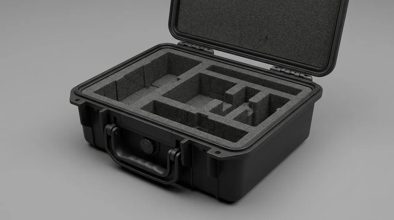
Impact isolation principles and material choice are covered in cushion liner design points, and areas that need high impact absorption are discussed in impact resistant case structure.
Retaining insulation condition and static protection on site
The real acceptance measure of packaging is whether the handover test can proceed without rework. That requires the insulation retention measures to be locked into the process.
Retaining insulation distance. Electrical clearance and creepage distance can shrink when parts shift. Specify restraint and displacement margin at design stage, then confirm by dimensional check or visual inspection on arrival that critical surfaces have not made contact.
Retaining surface cleanliness. Surface contamination on insulation sharply reduces flashover voltage. Use non-shedding materials, unpack in a clean area, and keep operators from handling insulation surfaces with bare hands.
Static protection. Secondary devices, sensors and electronic instrument transformer modules are static sensitive. A dissipative liner with controlled surface resistance, a grounding tab on the case and protective sleeves over exposed connectors form the basic set; where a project requires it, build the work instruction around ANSI/ESD S20.20, as described for ESD shielding cases.
Pre-test condition check. Add an appearance and cleanliness confirmation step before the handover test, recording insulation surface condition, bushing cracking and contact discolouration as the baseline for later results. Selection and testing of low-voltage switchgear and controlgear may reference GB/T 14048, and power transformer requirements may reference the GB 1094 series, in each case against the version in force.
Enclosure and liner material selection
Enclosure choice for substation parts weighs flame performance, weather resistance and reusability alongside strength.
| Enclosure option | Strength | Moisture control fit | Typical use | Watch points |
|---|---|---|---|---|
| --- | --- | --- | --- | --- |
| Sealed engineering polymer case | Medium to high | Excellent, easy to seal | Bushings, secondary devices, instruments | UV resistance, low-temperature embrittlement |
| Metal frame with panels | High | Medium, needs an inner liner | Large switchgear modules, winding assemblies | Internal insulation treatment essential |
| Timber crate with composite liner | Medium | Poor, needs a barrier film | One-way shipments of large items | Neutral acid-free timber plus barrier film |
| Rotomoulded one-piece case | High | Excellent | Repeat trips, outdoor projects | Higher tare weight, plan lifting points |
For the liner, an XPE and EVA combination works well: XPE for load bearing and large area support, moulded EVA for conforming restraint of brittle parts. Where moisture control and cushioning are both needed, use a closed-cell composite with a moisture barrier layer. Open-cell sponge should be used with caution on substation parts, because it both absorbs moisture and sheds debris, which is doubly hostile to insulation.
For assets that circulate for years, evaluate shell life and liner life separately: design the shell for many trips and treat the liner as a consumable. The amortisation logic for tooling investment is set out in custom case mould cost analysis.
Ingress protection and environmental test validation
Ingress protection addresses dust and water entry and is defined in IEC 60529, mirrored by GB/T 4208. For substation components the grade should match the mode of carriage, the storage condition and whether nitrogen or desiccant is used.
| Transport and storage condition | Suggested grade | Moisture configuration | Additional measure |
|---|---|---|---|
| --- | --- | --- | --- |
| In-plant or short transfer | Around IP54 | Humidity indicator card | Liner scratch protection |
| Long-haul road, ordinary warehouse | IP55 to IP65 | Desiccant plus indicator card | Pressure equalisation element |
| Sea freight, cross-border intermodal | IP65 to IP67 | Nitrogen blanket or high-capacity desiccant | Salt mist treatment, logger |
| Outdoor staging at site | IP66 to IP67 | High sealing plus data logger | UV resistance, anti-condensation |
For validation, select an ISTA procedure or an ASTM D4169 distribution cycle according to the mode of carriage, and reference the GB/T 4857 series for domestic requirements. Before testing, settle whether the sample includes a representative mass dummy, what the pass criteria are and which measurements are repeated afterwards. For substation parts the recommended criteria include no new cracking in porcelain, humidity indication within threshold for windings and oil-impregnated parts, undamaged contact faces and no loosened fasteners. The sequences are described in ISTA transport testing procedure and ASTM D4169 distribution cycle testing.
Where MIL-STD-810H methods are used for temperature, humidity, vibration or shock testing, the report must state that the standard is applied as an environmental test-method reference and does not constitute any military certification or qualification.
Lifting, handling and transport orientation
A large share of substation component packaging damage happens not on the road but during lifting and handling.
Lifting points. Mark the lifting points or forklift positions clearly and show the centre of gravity on the outer case. Off-centre loads are normal for these parts, so the marking must be accurate.
No sling compression. Slings should not run across the top of the case and compress it unless the structure has been validated for that load. Where compression is unavoidable, fit corner protectors between sling and case.
Orientation management. State the transport orientation and fit tilt and impact indicators, placing the two tilt indicators on adjacent faces so neither can be hidden. Photograph the indicators before opening.
Minimise handling events. Each transfer adds to the cumulative probability of impact. Reduce intermediate handling where possible, or use a reinforced pallet base suited to repeated lifting.
People and tools. Use insulated tools for unpacking and keep the floor free of metal swarf. For parts that are or may be energised, confirm earthing and discharge status before starting work.
Goods-in acceptance and site handover
Goods-in acceptance exists to move discovery as early as possible. Follow this order.
Step one, outer case and markings: check for damage, read tilt and impact indicators, and confirm waterproofing and moisture markings, lifting marks and document completeness.
Step two, acclimatisation: apply the specified standing time when the temperature differential is large, so condensation does not form on a cold part.
Step three, immediate reading after opening: read the humidity indicator card or the logger first, to establish whether the interior exceeded its threshold. This must happen before any other activity, otherwise the evidence is lost.
Step four, detailed appearance inspection: work through bushings, insulation parts, contacts and conductive faces, looking for cracks, discolouration, scratches and evidence of shifting.
Step five, insulation condition: re-measure insulation resistance as the project requires, add a dielectric test where specified, and record ambient temperature and humidity.
Step six, filing: archive the case serial number, component serial numbers, indicator readings, photographs and test data into one traceable record.
The acceptance principle is evidence first, disassembly second. Without the indicator readings, label status and appearance photographs, later liability analysis and insurance claims have no foundation.
Custom engineering and project supply support
Substation packaging typically combines many models, small batch sizes and tight delivery windows, which puts a premium on supplier responsiveness. For substation switchgear and transformer component cases of this type, the enclosures are produced by Kexin New Materials (Guangdong) Co., Ltd., which also serves overseas buyers through wholesale contracts and appointed agents, accepts OEM/ODM briefs based on drawings or physical samples, and issues material and inspection paperwork with contracted shipments. In power projects the most valuable custom capability is conforming restraint built around the bushing and contact positions while leaving room for the moisture control package, because that single decision governs both insulation retention and transport safety.
For a quotation, provide the component list with weights, overall dimensions and centre of gravity, a note on fragile areas, the mode of carriage and storage conditions, moisture and nitrogen requirements, lifting constraints and the document set needed. Where a project covers many variants, an adjustable liner with modular partitions raises reuse rates considerably. A general framework for vetting manufacturers is in how to choose a case OEM factory, and instrument-grade selection logic is covered in instrument case selection guide.
FAQ
Q: Why should a transformer bushing not be shipped standing upright?
A: The governing factor is the load path, not the posture itself. A bushing is a brittle, high aspect ratio part whose strength is highly sensitive to bending stress. Standing upright with imperfect base support turns the barrel into a cantilever, and vehicle vibration generates inertia forces that produce a large bending moment at the flange or where the barrel meets the sheds. If the case also has vertical clearance, the bushing can move up and down and generate impact as well. Shipping in the orientation the manufacturer specifies, combined with multiple restraint points, a rigid bearing face and compliant cushioning, keeps bending stress within acceptable limits. The rule is therefore to follow the manufacturer on orientation and to make restraint and support multi-point and load-path correct, rather than debating upright versus horizontal in the abstract. Whichever orientation is used, the decisive question is whether support and restraint suit it, and that is what the packaging drawing should state explicitly.
Q: How much desiccant is enough?
A: There is no universal figure. Estimate from three inputs: the free volume inside the case, the expected transit period, and the humidity and temperature conditions along the route. Work out the free volume, read the sorption curve of the specific desiccant, and back-calculate the quantity from the target humidity ceiling under the worst case, adding a safety margin. Three practical constraints apply: the desiccant must contact the internal air rather than sit in a corner, it must not introduce dust into insulation or contact areas, and if the case has a pressure balance element or a breathable membrane, outside moisture enters continuously so the quantity must rise or a nitrogen blanket should replace it. Verifying against a humidity indicator card on arrival is more useful than arguing about the number of sachets packed. Record the calculation and the assumption behind it, so that a change of route, carrier or season can be assessed against it rather than guessed at.
Q: Can packaging solve the problem of oxidised switchgear contacts?
A: Packaging substantially reduces the probability but cannot eliminate it, and it never replaces the manufacturer's surface treatment. Packaging controls environmental factors: it lowers humidity by drying, restricts outside moisture by sealing, avoids contact with sulphur-bearing or acidic materials by separation, and prevents plating damage by a conforming liner. It cannot undo an oxide film already formed during assembly or storage. Good practice therefore works both ends: the manufacturer controls plating quality and factory testing, the packaging controls humidity and contamination, and goods-in confirms by contact resistance or appearance. With packaging and receiving records in place, responsibility can be assigned quickly if a dispute arises. It also helps to separate the condition of the contact surface from the contact pressure. A face that looks clean may carry a thin oxide layer that only a resistance measurement detects, while a visibly marked face may measure perfectly well. Packaging influences the first, mechanism design and factory process influence the second.
Q: How can I confirm that moisture did not enter the case in transit?
A: Use evidence rather than inference, and preferably two instruments together. A humidity indicator card gives a discrete pass or fail judgement against a threshold. An electronic temperature and humidity logger gives a full time curve so the timing and duration of any excursion can be assessed. Both should sit where they represent the internal environment, not taped against the component or the desiccant. The first action on arrival should be to read and photograph the record, before opening. Where oil-impregnated parts demand more, combine nitrogen blanketing with a pressure indication to create a dual judgement of humidity and pressure. Two cautions apply here. A logger left in the case during long storage records that period too, so the interpretation must cover the whole timeline rather than the voyage alone. Indicator cards also have a shelf life and a defined activation threshold, so confirm the specification and the date code before relying on the result.
Q: How is responsibility assigned when porcelain is found broken?
A: Through three links in an evidence chain. First, the outer case and indicator status, including tilt and impact labels, which show whether a transport excursion occurred. Second, original images taken at unpacking, covering package appearance, restraint impressions in the liner and the damaged location on the porcelain. Third, the validation file for the packaging design, covering support method, restraint points and test reports, which indicates whether there is a design defect. With all three, responsibility generally separates into transport excursion, packaging design or component defect. The contract should therefore define the receiving evidence procedure and state what happens if it is not followed, so the discussion stays factual. It also helps to agree in advance who performs the inspection and who signs the record. Where consignee, carrier and supplier all have an interest in the outcome, one named person with a defined checklist removes most of the ambiguity before it turns into a commercial dispute.
Q: Which tests should be run on substation component packaging?
A: Combine them by mode of carriage, usually covering vibration, drop or impact and stacking, with sea freight often adding temperature and humidity cycling and salt mist protection. ISTA and ASTM D4169 provide frameworks that assemble tests according to the distribution chain, while the GB/T 4857 series provides general test methods. Three decisions must be made before testing: whether the sample carries a representative mass dummy, what the pass criteria are, and which measurements are repeated afterwards. Acceptance after the test should look at whether porcelain shows any fresh cracking, whether insulation surfaces picked up scratches or contamination, whether the humidity reading stayed inside its threshold, whether contact faces were marked, and whether any fastener came loose. Where MIL-STD-810H methods are cited, the report should note they serve as environmental test-method references only and confer no military certification. Whichever methods are selected, keep the raw data. Curves and readings that support a pass decision carry as much value as the decision itself when the project is audited later.
Q: What should be considered when using a timber crate?
A: A crate is not forbidden, but three things need extra attention. First, timber species and treatment: avoid grades that can release acidic substances, add a barrier film where needed, and keep timber away from oil-impregnated insulation and plated surfaces. Second, fasteners: staples and latches are metal conductors, and they must not be able to fall into the case in transit, which matters especially for energised parts. Third, hygroscopicity: timber absorbs and releases moisture with ambient conditions, which undermines the desiccant, so a timber crate usually needs an inner sealed bag or a barrier liner. For high-value or moisture-sensitive components, a sealed case is the safer default. A further detail is how the crate itself is fastened. Screws driven into end grain loosen under vibration, so joints should be designed for the handling the crate will actually see, and a returned crate should be checked for loose fasteners before each reuse.
Q: How can packaging cost be controlled on many-model, low-volume projects?
A: Generality in the liner is the main lever, and there are three routes. Use adjustable restraint, such as locating posts, movable dividers or grid inserts, to cover components of similar size and reduce dedicated tooling. Build the liner as a base layer plus a functional layer, so the base is common and the functional layer changes per component at far lower cost than a complete mould. And treat packaging as a circulating project asset with a defined return, count and reuse process, which spreads the initial investment over multiple trips. All three reduce cost per use, but they need a clear component list and size distribution first, otherwise generality is achieved at the expense of restraint quality. Documentation of the adjustments matters as well. If a functional layer is repositioned for a different component, record the change against the case serial number, otherwise the next user inherits an unknown configuration and restraint quality quietly degrades.
Conclusion and further reading
The measure of substation component packaging is not how heavy the case is, but whether the handover test can start on arrival without rework. Turning moisture control into readings, vibration control into restrained structure and insulation condition into a traceable record is what determines the real value of a packaging plan. Before the next substation project mobilises, write the acceptance sequence above into the material receiving work instruction and make evidence first, disassembly second a fixed habit.
Further reading