

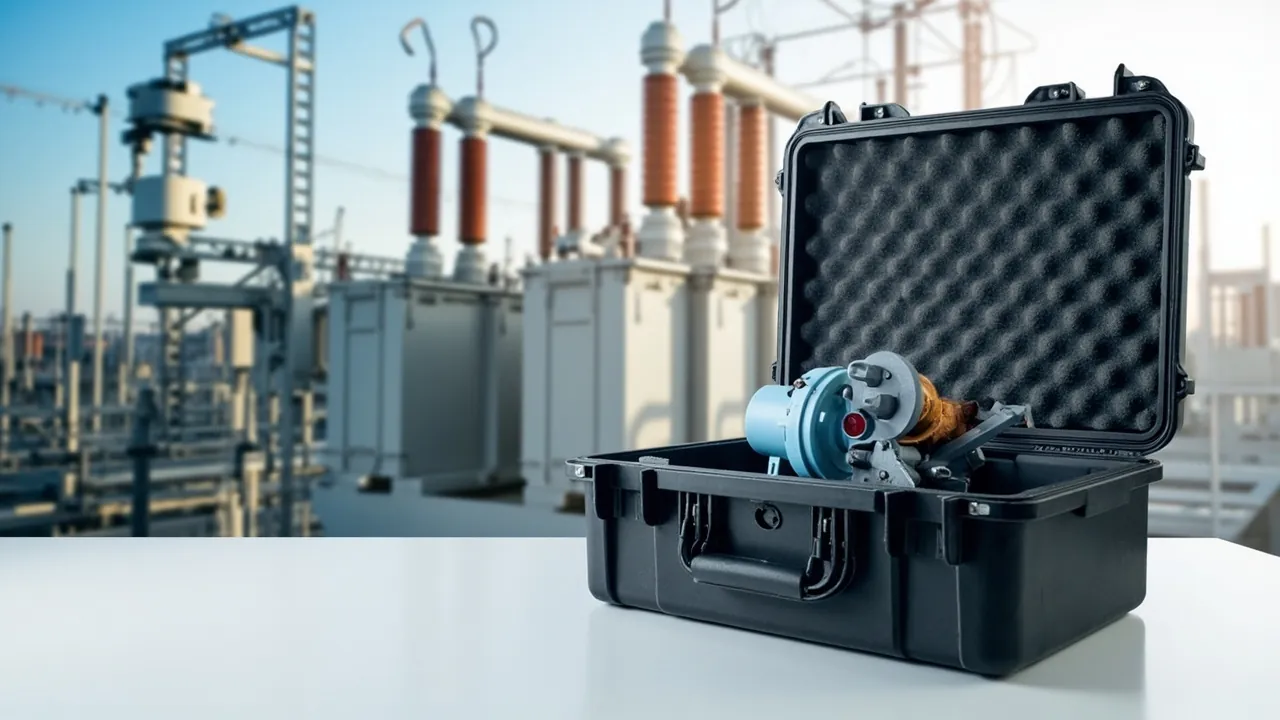
The hard part of shipping transformer components is never fitting them into a box. It is keeping porcelain bushings crack-free, winding insulation dry, conservator bladders unfolded and sealing faces unscratched across long multimodal journeys with large temperature and humidity swings. Field experience is consistent on this point: a meaningful share of the defects found during the first months of transformer service are not caused by operational degradation at all. They are latent damage introduced during transport and storage — hairline cracks in porcelain that pass a visual inspection, insulation components that absorb moisture during ocean freight and drive dielectric loss up, oil-level gauge glass that shatters under stacking load, and flange sealing faces indented by hard packaging materials. None of these show up during routine factory testing, yet all of them surface during site assembly or after energisation, when the cost of correction is at its highest.
Designing a dedicated transport case for transformer components therefore comes down to one thing: converting protection from a subjective impression into verifiable engineering parameters. Ingress protection ratings, compression and recovery curves for insert foams, water-vapour transmission rates for barrier films, and the transmissibility measured during drop and random-vibration testing are all values that can be written into a technical agreement and reproduced by a third party. "We wrap it in extra foam" cannot be verified, and it cannot be disputed either, which is precisely the problem.
This article is written for packaging, logistics and procurement engineers at transformer manufacturers, power engineering contractors, overseas EPC firms, grid spare-parts warehouses and third-party logistics providers. It breaks down the transport-protection requirements of bushings, winding and core insulation, conservators, coolers and tap changers, and provides material selection tables, a decision path for ingress protection ratings, the relevant ISTA and IEC test references, and a practical incoming-inspection method. If you retain only one idea from this article, make it this: the first priority of a transformer component case is the combined design of moisture control and vibration isolation; impact resistance comes second.
A transformer component case is normally engineered one part per case, or one group of identical parts per case. Housings are typically rotational-moulded HDPE or injection-moulded PP, with closed-cell EVA or PE inserts and a replaceable gasket plus a pressure equalisation valve. JUNZHJIA (Kexin New Materials (Guangdong) Co., Ltd.) builds OEM and ODM programmes around bushing models, winding transport-frame dimensions and conservator volumes.
Table of Contents
- 1. Why Transformer Components Are Harder to Ship Than Complete Units: Five Classes and Their Failure Modes
- 2. Bushing Cases: Differentiated Design for Condenser, Porcelain and GIS Bushings
- 3. Winding and Core Insulation Cases: Moisture Control Comes Before Vibration Control
- 4. Conservator and Oil-Tank Cases: Bladders, Diaphragms and Oil-Level Gauges
- 5. Coolers, Oil Pumps and Fan Assemblies: Heavy-Load Transport
- 6. Tap Changers and On-Load Voltage Regulators: Precision Protection
- 7. The Moisture-Control System: Desiccants, Humidity Indicators and Barrier Films
- 8. Vibration Isolation and Cushioning: Deriving Insert Thickness from the Transport Spectrum
- 9. Sealing and Ingress Protection: IP65 or IP67
- 10. Insert Material Selection: EVA, PE, PU and UL94 Flammability
- 11. Case Construction and Hardware: Hinges, Latches and Replaceable Gaskets
- 12. Lifting, Stacking and Transport Markings
- 13. Test Verification: ISTA, GB/T 4857 and IEC 60721
- 14. Procurement and Acceptance: Drawings, Samples and AQL Sampling
- Frequently Asked Questions
- Conclusion & Related Reading
1. Why Transformer Components Are Harder to Ship Than Complete Units: Five Classes and Their Failure Modes
A complete transformer travels under a defined transport envelope, with a known centre of gravity and a dedicated transport frame. Components are the opposite: a single large power transformer, once dismantled for shipment, generates anywhere from a few dozen to more than a hundred packaging units with completely different shapes, masses and fragility levels. Applying one cushioning specification across all of them produces the worst of both worlds — heavy parts that are under-protected and light parts that are wrapped far beyond what they need.
By failure sensitivity, transformer components fall into five classes, and each class follows a different protection logic.
| Component class | Typical items | Dominant failure mode | Protection priority | Key parameter |
|---|---|---|---|---|
| --- | --- | --- | --- | --- |
| Porcelain insulators | HV bushings, porcelain bushings, surge arresters | Porcelain cracking, shed chipping, flange displacement | Impact > vibration > moisture | Local cushion thickness, number of suspended support points |
| Insulation materials | Insulating pressboard, angle rings, cylinders, spacers | Moisture pickup raising water content and dielectric loss | Moisture > cleanliness > vibration | In-case relative humidity, barrier film WVTR |
| Oil-circuit parts | Conservator, oil tank, bladder, diaphragm | Bladder creasing, diaphragm blocking, gauge breakage | Moisture and vibration | Inert gas purge, crease-free bladder support |
| Sealing and connection parts | Flanges, butterfly valves, gaskets, bolt sets | Sealing-face scratching, rubber ageing | Cleanliness and contamination control | Face protection film, light and ozone exclusion |
| Precision electromechanical parts | Tap changer, oil pump, oil-level relay | Contact displacement, bearing damage, PCB vibration damage | Vibration > moisture | Random-vibration transmissibility, ESD protection |
The two classes most often overlooked are the second and the third. A cracked bushing shed is usually caught by visual inspection. Moisture pickup in insulating pressboard is invisible damage: pressboard stored for several days above 60 percent relative humidity can move from roughly 0.5 percent to over 2 percent water content, which directly raises the dissipation factor of the insulation system. On site, the only remedy is extended hot-oil circulation, and the schedule impact is severe. This is exactly why moisture control in a transformer component case deserves the same design weight as vibration isolation.
2. Bushing Cases: Differentiated Design for Condenser, Porcelain and GIS Bushings
Bushings are the most expensive, the most fragile and the hardest to pack of all transformer components. A condenser bushing rated 110 kV and above contains a multi-layer oil-impregnated paper capacitive core inside a porcelain or composite housing, with flanges at both ends that must be protected. Structurally, it dislikes bending, impact and moisture in equal measure.
For a condenser bushing, the preferred concept is two-point support with an unsupported mid-section. Two sets of profiled EVA or PU saddles, machined to the flange outside diameter, carry the bushing so that only the top and bottom flanges transmit load; the porcelain body touches no hard surface. The free mid-section allows a very small elastic displacement under vibration instead of forcing the porcelain to carry bending stress. For bushings longer than about 2.5 metres, an adjustable auxiliary restraint ring should be added inside the case, positioned according to the bushing's mass distribution, with a soft foam liner of Shore 25 to 35 hardness.
Porcelain bushings and surge arrester housings are structurally simpler, but their sheds chip more easily. The insert needs shed-relief pockets, and the pocket depth should be at least 1.1 times the shed outside diameter so that no shed edge carries load during transport.
GIS bushings and terminal bushings frequently carry SF6 compartment interfaces and density monitors. The case design must provide an independent protective cover position for the interface flange, and the density monitor must be treated as a separate vibration-isolated unit rather than sharing a cushioning cavity with the bushing.
One frequently missed detail is the lifting point. Bushings are lifted at the factory with flange lifting lugs, but if the transport case also has lifting eyes, the documentation must state clearly that case lifting points and product lifting points are separate systems, and the case must be labelled to prohibit lifting the case by the product lugs. When JUNZHJIA engineers a bushing case, lifting points, stacking points and product load paths are three independent systems, and the case is screen-printed with a lifting diagram and centre-of-gravity marks to reduce on-site errors.
3. Winding and Core Insulation Cases: Moisture Control Comes Before Vibration Control
The winding assembly normally travels with the core and coil unit. What genuinely needs its own case are the loose items: insulating pressboard, angle rings, insulating cylinders, laminated wood, spacers, lead insulation, plus spare and regulating winding assemblies. Their common characteristic is that mechanical strength is adequate while moisture uptake is extreme.
The equilibrium moisture content of insulating pressboard varies strongly with ambient humidity. For typical transformer pressboard at 25 degrees Celsius, equilibrium water content is roughly 5 to 6 percent at 40 percent relative humidity, and can reach 11 to 13 percent at 80 percent relative humidity. Every additional percentage point of water content measurably degrades dielectric loss and the partial-discharge inception voltage of the insulation system. The design focus for these components is therefore not how thick the foam is, but how well the environment is isolated.
A workable approach uses three layers:
- Inner layer: an aluminium-foil composite barrier bag, vacuum-drawn or filled with dry air, with at least three humidity indicator cards distributed at both ends and the middle of the bag.
- Middle layer: closed-cell EVA or PE foam to constrain geometry and prevent pressboard edges from rubbing against each other and raising fibres.
- Outer layer: a rigid rotational-moulded or injection-moulded case with IP65 or better sealing, and a replaceable desiccant pack inside.
One point deserves emphasis: a perfectly sealed case develops negative pressure when temperature changes. During ocean freight, the outside of a container can be more than 20 degrees Celsius cooler at night than the inside, and the contracting internal air will draw moist external air past the gasket. This is the breathing effect. The solution is a pressure equalisation valve that passes air but not liquid water, allowing the pressure differential to equalise slowly while blocking liquid ingress and condensation. The structural principle is described further in how a protective case pressure equalisation valve works.
4. Conservator and Oil-Tank Cases: Bladders, Diaphragms and Oil-Level Gauges
A conservator looks like an empty shell, but in practice it is one of the higher-return-rate categories in component transport. Its internal bladder or diaphragm is a rubber or composite film, and once a crease forms under sustained compression during transport, that crease becomes a permanent deformation and eventually a micro-crack. The result after energisation is a conservator that no longer breathes correctly, together with abnormal dissolved gas in the oil.
Three design points matter for conservator cases:
- The bladder must be inflated with inert gas or dry air to a slight positive pressure so that it rests against the tank wall instead of collapsing into free folds. Charge to the manufacturer's specified pressure and attach a pressure recording label inside the case; compare the reading before dispatch and after arrival.
- Oil-level gauges and oil-level relays must be removed and packed separately, never transported with the conservator body. The probability of a glass tube gauge breaking under stacking load is high, and the fragments contaminate the tank interior.
- Anti-rolling restraints are required inside the case. Conservators are long cylinders, and under horizontal transport without axial thrust blocks, braking forces will slide the body into the end wall. Specify PE buffer blocks at least 80 mm thick at the ends, with 5 to 10 mm of compression allowance.
For the diaphragm-type conservators used on large transformers, the diaphragm is a single rubber sheet. During transport it should be rolled rather than folded and braced: the roll diameter should not be less than about 300 mm, the core should be a rigid paper tube, and the roll should be wrapped in non-woven fabric before going into the case. Stress concentration at a fold line is the leading cause of early diaphragm failure.
5. Coolers, Oil Pumps and Fan Assemblies: Heavy-Load Transport
Cooler banks (panel radiators and forced-oil forced-air coolers), oil pumps, oil-flow relays and fans combine heavy mass, easy deformation and oil ports. Their protection logic is entirely different from the components discussed so far.
Panel radiators suffer most from unsupported span. The panels are thin sheet structures, and if a case supports only the end flanges while the panel body spans freely, stacking pressure during transport will bow the panel permanently. The correct approach is multiple equally spaced support battens inside the case, with a spacing not exceeding about 400 mm and a height tolerance within plus or minus 1 mm, so that load is distributed evenly.
Oil pumps and oil-flow relays are precision electromechanical parts. Their cushioning layers should be designed against random-vibration conditions, every oil port must be fitted with a blind flange or plug, and the case should include a bag of removed seals and small parts so that the site team is not hunting for bolts.
Fans and motor assemblies concentrate mass at the motor end. The case should use the motor side as the primary load-bearing surface, and the exterior should carry centre-of-gravity marks and a this-side-up label. For cooler units weighing more than about 200 kg, the case must provide forklift pockets or lifting apertures, and the base should include a detachable pallet structure so the unit can be rolled and stacked directly.
Heavy-load cases require different materials from light ones. Rotational-moulded HDPE formed in a single piece with 6 to 10 mm wall thickness and reinforced ribs in the base is the usual specification. For this class, JUNZHJIA typically pairs a rotational-moulded housing with a steel-reinforced pallet base, balancing weather resistance against stacking strength, and makes the hardware replaceable to extend service life. Material density and weathering behaviour are covered in protective case service life and replacement criteria.
6. Tap Changers and On-Load Voltage Regulators: Precision Protection
Tap changers are often packed by default into a wooden crate using the same standard as the main unit, and then become the hardest part of on-site commissioning. An on-load tap changer contains a drive mechanism, a contact system and a diverter switch, and its tolerance to shock and vibration is far lower than its robust appearance suggests.
Three principles apply:
- Never ship in a bare wooden crate. A crate provides no geometric constraint, and the changer will shift and tumble in transit. Use a rigid case with a profiled insert that matches the body contour, with compression controlled between 10 and 15 percent.
- Design the cushioning against random vibration, not a single drop. Road transport excites a broadband random-vibration response rather than one clean impact event, so the cushion must provide damping across the mid and high frequency bands. A closed-cell EVA and PU combination usually outperforms simply thickening the PE layer.
- Restrain the drive mechanism. Removable handles, linkages and gear sets should be wrapped separately so that they cannot become free projectiles inside the case.
For on-load changers with electronic control units, such as motor-drive mechanisms and position transmitters, ESD protection also matters: control boards go into antistatic bags, and plain foams that generate static should be avoided inside the case. The material pairing logic is described in ESD shielding case design essentials.
7. The Moisture-Control System: Desiccants, Humidity Indicators and Barrier Films
Moisture control is what separates a transformer component case from an ordinary tool box. A complete system has four layers, and losing any one of them defeats the whole.
The first layer is the barrier. An aluminium-foil composite film with a PET/AL/PE structure typically shows a water-vapour transmission rate in the region of 0.1 g per square metre per 24 hours, far below a plain PE bag. For insulation parts and bushing cores, a barrier bag is the single most cost-effective protective layer available.
The second layer is the desiccant. Silica gel with an indicator, or molecular sieve, are the usual choices. Desiccants containing chlorides should not be used near insulation components. Capacity is estimated from the free volume inside the case and the target humidity; a common engineering rule of thumb is 0.5 to 1.0 kg of silica gel per cubic metre of free volume, corrected for the storage period and the initial moisture content. Desiccant should be suspended from the upper part of the case rather than touching the product.
The third layer is humidity indication. Place at least three points: one at each end inside the barrier bag and one in the case void. Reversible indicator cards are preferable so that they remain usable after a mid-journey inspection.
The fourth layer is structural sealing. The gasket material and compression ratio determine whether the first three layers work at all. A compression ratio between 25 and 35 percent is typical: too low and the seal leaks, too high and the gasket takes a permanent set and loses resilience. Gaskets should be replaceable items rather than co-moulded into the housing.
One practical warning: after any inspection opening, the desiccant must be replaced and the case resealed. A large share of field problems trace back to a case that was opened for sampling and then simply closed again. Fitting a one-time wire seal position or a tamper-evident label on the case makes the opening event traceable.
8. Vibration Isolation and Cushioning: Deriving Insert Thickness from the Transport Spectrum
Cushion design is not about thickness alone. The objective is to hold the acceleration transmitted to the product below its allowable limit under a given input spectrum. For transformer components, allowable acceleration depends on the item: porcelain bushing bodies are usually controlled in the 0.5 g to 1.0 g range, precision electromechanical parts at 1.0 g to 2.0 g, and heavy metal parts can be allowed above 5 g.
The engineering sequence runs as follows:
- Establish the input conditions. Road transport uses the random-vibration spectra in the ISO 13355 and GB/T 4857 series; rail and sea freight have their own spectra; multimodal shipments take the envelope.
- Establish the allowable acceleration and the product resonance. If the resonant frequency of a brittle part falls in the 5 to 30 Hz band, frequency isolation is mandatory rather than simply adding thickness.
- Size the support area from static load. The static stress in the foam should stay below 60 percent of the stress corresponding to 25 percent compression, so that the foam does not creep under sustained load and lose its resilience.
- Check thickness against drop and shock conditions. Use the drop heights in ISTA 3E or GB/T 4857.5 to determine the minimum cushion thickness.
- Verify with real hardware. Load the actual component into a sample case, run random vibration and drop tests, and measure the acceleration on the inner surface of the insert against the allowable value.
One point deserves emphasis: resonance, not insufficient thickness, is the most common cause of cushioning failure. When the case, insert and product form a system with an amplification factor above 3 near 8 to 15 Hz, the product sees higher acceleration than if it had been rigidly fixed, no matter how thick the foam is. The remedies are to change insert stiffness by layering foams of different densities, or to add an isolation pad between the case and the pallet. Test methodology is covered further in how to select and run ISTA transport testing procedures.
9. Sealing and Ingress Protection: IP65 or IP67
The ingress protection rating drives both cost and applicability, and choosing the highest rating by default is not good engineering. Under IEC 60529 and GB/T 4208, the relevant grades are:
| Rating | Dust | Water | Typical application | Relative cost |
|---|---|---|---|---|
| --- | --- | --- | --- | --- |
| IP54 | Partial dust protection | Splash resistant | In-plant movement, dry warehouse, short haul | Low |
| IP65 | Dust tight | Water jet resistant | Domestic road transport, general warehousing | Medium |
| IP67 | Dust tight | Temporary immersion, 1 m for 30 min | Ocean freight, open yards, multimodal | Medium-high |
| IP67 with pressure equalisation valve | Dust tight | Immersion plus differential pressure equalisation | Reefer containers, long trans-climate shipments | High |
The decision reduces to three questions: will the case travel in an ocean container through large day-night temperature swings; will it be stored in the open; will it encounter standing water or washdown? If any answer is yes, specify at least IP67.
Note carefully that an IP rating evaluates dust and water ingress only. It says nothing about cushioning, nothing about moisture barrier performance, and nothing about stacking strength. An IP67 case with a poorly designed insert can still crack a bushing. Nor does an IP rating cover salt-spray corrosion, which must be addressed separately in ocean freight through housing material selection and hardware surface treatment. Further verification methods are set out in IP67 protective cases: structure, sealing and verification.
10. Insert Material Selection: EVA, PE, PU and UL94 Flammability
Insert material selection balances cushioning performance, machinability, weather resistance, cleanliness and flammability.
| Material | Density (kg/m3) | Recovery behaviour | Processing | Strengths | Limitations |
|---|---|---|---|---|---|
| --- | --- | --- | --- | --- | --- |
| Closed-cell EVA | 60-120 | High resilience, recovers after repeated compression | CNC milling, thermoforming | Dimensionally stable, easy to profile | Higher cost |
| Closed-cell PE | 25-70 | Slow recovery, good energy absorption | Die cutting, lamination | Low cost, strong energy absorption | Prone to permanent set |
| PU foam | 20-60 | Good damping, effective at mid and high frequency | Casting, die cutting | Strong vibration isolation | Moderate weathering resistance |
| EPP moulded parts | 30-60 | Excellent resilience | In-mould forming | Complex three-dimensional geometry | Requires tooling |
| Laminated assemblies | Varies | Stiffness can be designed in stages | Multi-layer bonding | Tunable, suppresses resonance | Complex process |
For brittle porcelain parts, the recommended combination is an EVA profiled saddle with a PE energy-absorbing layer: EVA provides geometric constraint and resilience while PE absorbs impact energy. For precision electromechanical parts, PU or EPP works better as the damping layer. For pressboard-type components, the inner layer should be a clean, acid-free and sulphur-free foam so that leachables cannot contaminate the insulation.
On flammability, both the housing and insert materials should be assessed against UL94. A transformer component is not energised during transport, but substation and warehouse environments still justify foam qualified to UL94 HF-1 or V-0. This is not only a fire-safety matter; it appears on the acceptance checklists of some overseas owners. For a fuller comparison of the selection dimensions, see case foam material comparison and selection and EVA foam insert custom fabrication process.
11. Case Construction and Hardware: Hinges, Latches and Replaceable Gaskets
The housing carries the whole protection system, and its construction determines long-term reliability. The three common forming processes each trade off differently:
- Injection-moulded PP or ABS housings offer high dimensional accuracy and good appearance, and suit small and medium components, but tooling cost is high and stiffness falls as size increases.
- Rotational-moulded HDPE housings scale to large sizes, resist impact and weather well, and suit bushings and coolers, but dimensional accuracy and appearance consistency are lower than injection moulding.
- Aluminium or steel frame cases give the highest stiffness for very heavy parts, but they are heavy, demand careful gasket assembly and corrode unless surface treated.
Whichever process is used, hardware is the weak link over time. Hinges carry the lid mass and repeated cycling, and latches must deliver consistent compression to maintain gasket compression ratio. Recommendations:
- Use stainless steel hinge pins with anti-loosening features, so that vibration does not walk the pin out over time.
- Space latches according to case edge length, generally at least one per 400 to 500 mm.
- Use a replaceable inset or channel-retained gasket, and supply spares with the case.
- Validate all exposed metal parts by salt-spray testing; for ocean freight, specify at least 96 hours of neutral salt spray with no red rust.
The matching logic and common failure modes of hinges, latches and gaskets are described in toolbox hinge, latch and gasket structure explained. JUNZHJIA can supply compatible replacement hardware to an existing case specification, or treat hardware as an independent module within an OEM or ODM programme with full lifecycle spare-part supply, reducing the customer's long-term maintenance cost.
12. Lifting, Stacking and Transport Markings
Even a well-designed case loses its protection the moment lifting and stacking are done incorrectly. Transformer component cases need four marking groups and four operating rules.
Four marking groups:
- Centre of gravity, with longitudinal and transverse datum lines.
- Permitted stacking layers, or a do-not-stack instruction.
- Lifting point positions with a diagram, and a prohibition on using product lifting lugs.
- Handling symbols to GB/T 191 for keep-dry, this-side-up and fragile.
Four rules:
- The compressive strength of the case top must match the stated stacking layers, and it must be verified by physical stacking tests rather than calculated alone.
- When cases of different sizes are mixed, heavy cases go at the bottom, and a large case must never bridge across the mid-span of a smaller one.
- Long cases for bushings need axial end stops so the product cannot travel along the case in transit.
- Stacking inside a sea container must account for container accelerations and lashing points, and lashing straps must not bear directly on product load-bearing faces.
Stacking strength verification also has a standards basis. Domestic shipments can reference the GB/T 4857 stacking test methods, while international shipments typically reference the ISTA procedures. The applicability logic is covered in GB/T 4857 transport packaging test methods explained.
13. Test Verification: ISTA, GB/T 4857 and IEC 60721
The final credibility of any packaging design comes from test data. At minimum, a transformer component case should complete the following verification programme.
| Test | Reference | Typical condition (example) | Pass criteria |
|---|---|---|---|
| --- | --- | --- | --- |
| Random vibration | ISTA 3E / GB/T 4857.23 | Road spectrum, 60-120 min | No product displacement, no insert collapse, acceleration below allowable |
| Drop and shock | ISTA 2A / GB/T 4857.5 | Height by weight class | No through-wall damage, product functions normally |
| Stacking | GB/T 4857.3 | Specified load, 24 h or more | Case deformation recovers, no product damage from load |
| Water and dust ingress | IEC 60529 / GB/T 4208 | IP65 / IP67 | No dust ingress, no harmful water entry |
| Climatic conditioning | IEC 60721-3 climate classes | High-temperature and humidity cycling | No condensation, insulation moisture content controlled |
| Salt spray (ocean freight) | Neutral salt spray test | 48-96 h | No red rust on hardware, no coating blistering |
| Environmental methods (reference) | MIL-STD-810H methods | Vibration, shock, humidity methods | Used as a test-method reference only |
On MIL-STD-810H, one clarification is essential: the standard is cited to borrow its well-established test methodology (Method 514 vibration, Method 516 shock, Method 507 humidity, among others); it does not indicate any military certification of the product. Commercial documents should describe the work accurately as verification conducted in accordance with the relevant MIL-STD-810H test methods, to avoid misinterpretation. See MIL-STD-810H and protective case environmental testing for further explanation.
At least three test samples are recommended: one for vibration and drop, one for stacking and climatic conditioning, and one retained as a reference. After testing, the case must be opened and the product inspected for function and appearance; evaluating only the exterior of the case is not sufficient to declare a pass.
14. Procurement and Acceptance: Drawings, Samples and AQL Sampling
Transformer component cases are custom products, and three stages generate most commercial disputes: insert drawing approval, sample approval, and batch consistency.
At drawing approval, lock down the product envelope and tolerances, the insert cavity layout, the grip positions and part-removal method, the case outline and stacking orientation, the marking content and placement, and the hardware specification and approved brands. Ask the supplier for a three-dimensional insert drawing and section views; photographs alone are not sufficient.
At sample approval, perform a physical loading check: place the actual component into the sample case and inspect for unsupported spans, interference fits and hard contact points. Where possible, run a short-haul transport trial and inspect displacement and indentation marks on opening.
At batch acceptance, use a sampling plan. Apply variable inspection to critical dimensions such as insert cavity size, gasket compression ratio and hardware mounting strength, and attribute inspection to appearance and markings, following the logic of GB/T 2828.1. A worked approach is set out in custom case acceptance and AQL sampling methods.
The documentation package is often overlooked at purchase but is the most valuable item later. Specify in the purchase order that the supplier must provide material certificates covering foam density and flammability grade and housing material, gasket material and hardness reports, ingress protection self-test or third-party test reports, the test reports for vibration, drop and stacking, plus a packing work instruction and a spare parts list. For transformer component case programmes, JUNZHJIA can supply this documentation package to customer requirements and coordinate third-party inspection on a sampling basis.
Frequently Asked Questions
Q: Must a transformer bushing case always be IP67, or is IP65 adequate?
A: There is no universal answer; the deciding factor is the transport route, not the value of the product. If the bushing travels only by domestic road and is stored under cover without ocean container exposure, IP65 is usually sufficient, since a dust-tight case with water-jet resistance covers normal conditions, and the cost is typically 15 to 25 percent lower. Upgrade to IP67 if any of the following applies: the case crosses climate zones by sea, where container day-night temperature differentials can exceed 20 degrees Celsius and cause repeated condensation inside the case; the case is stored or transhipped in an open yard; or standing water, washdown or driving rain is possible. In these conditions a pressure equalisation valve matters more than the rating itself, because a tighter seal actually increases the breathing effect that draws external moisture in. One further point is often missed: an IP rating only addresses water and dust entering from outside. It does not remove moisture already inside. The bushing carries residual moisture from the assembly shop, and the insert materials themselves release vapour. Those must be handled by desiccant and a barrier film, so the two systems must always be used together.
Q: How much moisture protection is actually required for pressboard and angle rings?
A: The most reliable approach is to write in-case relative humidity into the technical agreement rather than a generic requirement to keep parts dry. A practical specification is: an aluminium-foil composite barrier bag on the inner layer, vacuum-drawn or dry-air filled and heat sealed; at least three reversible humidity indicator cards inside the bag; replaceable silica gel desiccant in the case at the rule-of-thumb rate of 0.5 to 1.0 kg per cubic metre of free volume; and case sealing of IP65 or better with a pressure equalisation valve. The acceptance criteria can then be stated as relative humidity below 30 percent at dispatch, remaining below 45 percent after 30 days in transit, with no irreversible colour change on the indicator cards. Any intermediate inspection opening must be followed by desiccant replacement and resealing, with a wire seal or tamper-evident label retained for traceability. Without that traceability, the moisture-control record cannot be substantiated.
Q: Is there a rule-of-thumb insert thickness that can be applied directly to transformer component cases?
A: No universal value exists, but a clear engineering path does. First establish the input conditions, which means the random-vibration spectra for road, rail and sea transport, taking the envelope for multimodal shipments. Second, establish the allowable acceleration for the brittle features and their natural resonant frequency; porcelain bushings are typically controlled between 0.5 g and 1.0 g. Third, size the support area from static load so that the static stress in the foam stays below 60 percent of the stress at 25 percent compression, preventing creep. Fourth, back-calculate the minimum cushion thickness from the drop conditions in ISTA or GB/T 4857. Fifth, verify with real hardware by measuring the acceleration on the inner insert surface against the allowable limit. As an indication, porcelain parts under 20 kg commonly use a 30 to 50 mm EVA profiled saddle plus a 20 mm PE energy-absorbing layer, while cooler assemblies in the 100 kg class rely mainly on multiple support battens and can use a thinner cushion. Avoiding system resonance matters far more than adding thickness.
Q: Should a conservator bladder be inflated or vacuum-drawn for transport?
A: It should be held at a slight positive pressure with dry air or inert gas, never vacuum-drawn. Bladder and diaphragm failures usually originate from stress concentration at a crease, and vacuum drawing collapses the bladder completely into sharp folds. Under sustained compression those folds take a permanent set and eventually micro-crack, which shows up after energisation as impaired breathing and abnormal dissolved gas in the oil. Charge the bladder to the manufacturer's specified pressure so it lies against the tank wall, and attach a pressure recording label inside the case showing the pre-dispatch and post-arrival readings; a pressure drop beyond the permitted range marks a transport anomaly that requires internal inspection. Two further points are equally important: oil-level gauges and oil-level relays must be removed and packed separately rather than travelling with the conservator body, and large diaphragm components should be rolled rather than folded, with a roll diameter of at least 300 mm over a rigid paper tube core.
Q: How should salt-spray corrosion be handled on transformer component cases for ocean freight?
A: Address it at three levels: housing material, hardware and the internal packaging environment. For the housing, rotational-moulded HDPE performs well against salt spray and is the usual first choice for sea freight. If a metal frame case is used, steel parts need hot-dip galvanising or a primer plus topcoat system, while aluminium parts should be anodised. Hardware is the weakest link in any case: hinge pins should be 304 or 316 stainless steel, and latches and rivets equally need corrosion protection, with the assembly ideally passing at least 96 hours of neutral salt spray without red rust. For the internal environment, remember that salt-spray conditions bring chloride-laden moisture, so critical insulation components should be individually sealed in aluminium-foil barrier bags with desiccant and humidity indicator cards inside the case. Stacking loads and vessel vibration inside the container should be considered at the same time, and stacking strength should be validated by physical test rather than calculation.
Q: What special cushioning requirements apply to precision parts such as tap changers?
A: A tap changer is unusual because it contains a drive mechanism, a contact system and a diverter switch. It tolerates cosmetic damage well but is highly sensitive to acceleration and displacement, and failures typically only appear after energisation. Three requirements dominate. First, never ship in a bare wooden crate: a profiled insert must constrain the geometry, matching the body contour with compression controlled between 10 and 15 percent, tight enough not to shift but not an interference fit. Second, design the cushion against random vibration rather than a single drop, because road transport excites broadband random vibration; the cushion needs damping across roughly 5 to 200 Hz, and a closed-cell EVA and PU combination usually outperforms simply thickening the PE layer, with layered foams of different densities used to suppress resonance peaks where necessary. Third, restrain the drive mechanism: removable handles, linkages and gear sets should be wrapped separately and fixed so they cannot become free projectiles striking the body. On-load changers with electronic control units additionally need ESD protection, with control boards sealed in antistatic bags.
Q: What should be inspected during acceptance of custom transformer component cases, and what sampling plan is appropriate?
A: Divide acceptance items into three groups with different treatment. The first group covers safety and function critical dimensions: insert cavity dimensions and geometry, gasket compression ratio, hardware mounting strength and case stacking height. These warrant variable inspection with a tighter acceptance quality limit under GB/T 2828.1, typically AQL 1.0 or even 0.65. The second group covers appearance and marking: housing surface defects, marking content and placement, and print clarity. These are attribute characteristics and can use AQL 2.5. The third group covers verification of material and process, including foam density and flammability grade, housing wall thickness and hardware material, normally handled as a batch-level type verification rather than piece-by-piece inspection. Beyond the three groups, two further steps are worth building into the purchase order. The first is specifying the documentation package as a deliverable, so that certificates and test reports arrive with the goods rather than months later. The second is requiring that the first production batch include a physical loading plus short-haul transport trial, with inspection of displacement, indentation and restraint condition on opening. In practice this trial is the single most effective step in the whole acceptance process, and it is also the one most frequently skipped when schedules tighten.
Q: What customisation capability does JUNZHJIA offer for transformer component cases?
A: JUNZHJIA (Kexin New Materials (Guangdong) Co., Ltd.) provides transformer manufacturers, power engineering contractors and overseas EPC firms with an end-to-end capability from design through volume delivery, built on four pillars. First, model-specific inserts: using customer three-dimensional data for bushings, conservators and coolers, the team designs EVA, PE and PU profiled inserts with cavity layouts and issues insert drawings for approval. Second, housing and hardware customisation: injection moulding, rotational moulding or metal frame construction is selected according to part type and mass, and hinges, latches and gaskets can be matched to an existing customer specification with full lifecycle spare-part supply. Third, protection ratings and testing: IP65 and IP67 verification can be completed to IEC 60529 and GB/T 4208, and third-party vibration, drop, stacking and salt-spray testing can be coordinated with the corresponding documentation package. Fourth, OEM and ODM supply with global delivery, including customer branding, packing work instructions and volume delivery scheduling.
Conclusion & Related Reading
Designing a transformer component case is fundamentally an exercise in redefining protection. It takes the vague notion of a sturdy box and breaks it into four measurable technical lines: moisture barrier performance, cushioning energy absorption, sealing and structural integrity, and stacking strength. Each line then needs a standards basis, test data and an acceptance method. Bushings fear bending and impact; insulation components fear moisture; conservators fear bladder creases; tap changers fear random vibration; coolers fear unsupported spans. Different components need different parameter combinations, and applying one cushioning specification across all of them is the most common source of failure in this class of project.
The practical advice is straightforward. Fix the insert geometry and load paths at the drawing stage. Validate with a physical loading and short-haul transport trial at the sample stage. Then write the material, test and acceptance requirements into the technical agreement. Do these three things and the great majority of transport damage is eliminated during design, instead of being diagnosed during emergency repairs on site.
Related Reading