

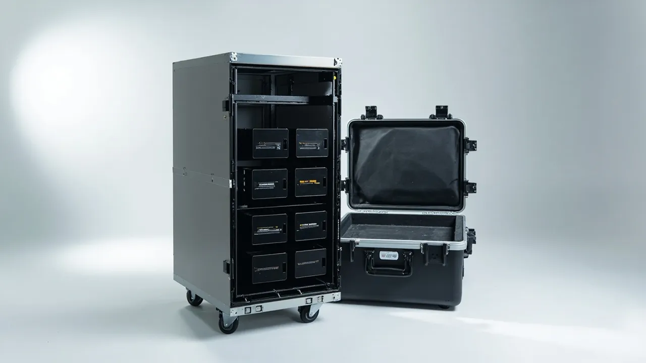
Shipping parts for a UPS battery cabinet is not the same problem as shipping ordinary industrial hardware. A single cell rated at tens of amp-hours can release enough current to vaporise a conductor the instant a metal object bridges its terminals, and a drop that pinches the separator inside a cell may only reveal itself as thermal runaway weeks later. The core metrics for battery packaging are therefore not impact resistance alone. They are insulation, short-circuit prevention, state of charge and impact control, all four held at the same time, each with evidence that can be checked.
This article is written for UPS assemblers, energy storage integrators, DC power system builders and maintenance buyers. It works through the requirements for cells, modules, interconnecting busbars, BMS sensing harnesses and cabinet switching devices in the order of risk source, material, structure, test and acceptance. It also sets out how JUNZHJIA supports custom packaging for energised components. Regulations cited here should always be checked against the version in force, and the intended mode of carriage should be confirmed with a carrier qualified in dangerous goods before dispatch.
Contents
- Why battery parts need their own packaging logic
- Four transport risk families seen from the risk side
- Dangerous goods rules and the baseline set by UN 38.3
- Terminal insulation and short-circuit prevention in practice
- State of charge management and transport safety
- Structural restraint for modules and racks
- Holding insulation performance and re-measuring it
- Static control and electrochemical corrosion
- Temperature window and thermal management
- Liner and enclosure material selection
- Ingress protection, environmental testing and regulatory references
- Goods-in inspection, storage and racking handover
- Custom development and volume supply capability
- FAQ
- Conclusion and further reading
Why battery parts need their own packaging logic
The usual wooden crate lined with foam assumes that the only thing to avoid is physical breakage. For a battery part that assumption misses three decisive mechanisms. First, a metal tool, a loose screw or even a staple can migrate inside the case and bridge terminals, creating an external short circuit. Second, foam and plastic liners accumulate static charge through repeated rubbing, and the discharge energy is enough to damage a BMS acquisition board or a cell protection circuit. Third, a cell is an electrochemical system, so mechanical damage does not necessarily crack like metal; it hides first and fails later.
Battery packaging must therefore satisfy electrical safety constraints before cushioning is even discussed. Reverse the order and you get a case that survives the trip but delivers a module with short-circuit burn marks. The practical industry approach is to reclassify cells and modules by three attributes, namely energised, short-circuit sensitive and heat sensitive, then define packaging requirements per class: energised parts drive insulation and separation, short-circuit sensitive parts drive individual terminal protection, and heat sensitive parts drive temperature window and thermal isolation.
On cost, battery packaging carries a much higher unit value than ordinary industrial hardware. A single transport incident involves component loss, site downtime, insurance negotiation and compliance tracing, and the last two frequently exceed the value of the parts themselves. Spending a little more on insulation and separation is therefore the highest-return item in the budget, not a line item to trim. Where a project includes both liquid-cooling parts and battery parts, the cleanliness and insulation requirements can be assessed together; see the notes on data center cooling component cases.
Four transport risk families seen from the risk side
Grouping the problem into four families makes it easier to pair each one with a measure and an acceptance metric.
Short circuit risk. Bare terminals, intruding foreign objects and busbars touching between modules. Controls are terminal boots, insulating barriers and a case interior free of loose metal.
Impact risk. Handling drops, stacking compression and vibration that deforms cell cans. Controls are restrained liners, validated drop testing and a defined stacking ceiling.
Thermal risk. High ambient temperature accelerates ageing while low temperature degrades electrolyte behaviour, and an abnormal internal short can escalate toward thermal runaway. Controls are a defined temperature window and thermal isolation.
Insulation and static risk. Creepage distance compressed by movement, and electrostatic discharge damaging BMS and protection circuits. Controls are insulation material selection, a grounding provision and dissipative materials.
| Risk family | Main trigger | Design response | Goods-in check |
|---|---|---|---|
| --- | --- | --- | --- |
| Short circuit | Foreign object bridging, busbar contact | Terminal boots, insulating barriers | No burn marks, no debris |
| Impact | Drops, stacking, vibration | Restrained liner, stacking ceiling | No deformation or swelling |
| Thermal | Heat ageing, internal short | Temperature window, thermal isolation | No abnormal heat traces |
| Insulation and static | Reduced creepage, ESD | Dissipative materials, grounding point | Insulation resistance passes |
Dangerous goods rules and the baseline set by UN 38.3
Lithium batteries are dangerous goods, and carriage is governed by international and domestic rules at the same time. Several points are non-negotiable.
UN 38.3. Section 38.3 of the United Nations Manual of Tests and Criteria sets out the transport safety tests for lithium batteries, covering altitude simulation, thermal cycling, vibration, shock, external short circuit, impact, overcharge and forced discharge. It is the precondition for a battery entering the transport chain and is normally completed by the cell or battery maker, with a test summary supplied to downstream users.
UN numbers and packing instructions. Lithium ion cells and batteries shipped on their own generally fall under UN 3480 or UN 3481, with packaging subject to the applicable packing instruction covering packing group, quantity limits and marking. When cells are contained in equipment or packed with equipment, different conditions apply.
Modal differences. Road (ADR), rail (RID), sea (IMDG) and air (IATA DGR) rules differ on state of charge limits, package markings and documentation, with air freight usually the most restrictive on state of charge. A practical summary is given in ADR and IMDG hazmat transport packaging.
Damaged and recalled cells. Cells that are damaged, likely to rupture or recalled for safety reasons are subject to stricter packaging and declaration requirements and must never be handled as ordinary cargo.
One point deserves emphasis: the case is part of the package, not the whole of it. A protective case addresses mechanical, insulation and separation concerns, while regulatory compliance additionally involves marking, documentation, state of charge and carrier acceptance. The two workstreams must proceed in parallel and cannot substitute for one another.
Terminal insulation and short-circuit prevention in practice
This is the most commonly underestimated step and the one that produces the clearest differentiation. Five practices cover most of it.
First, protect every terminal individually. Fit insulating boots or caps over the posts, made from a material that resists electrolyte, handles the transport temperature range and does not embrittle. The boot must cover down to the base of the post, not just the end face, so that a metal object cannot bridge across the side.
Second, install insulating barriers between modules and between modules and the case wall. The barrier must have adequate withstand voltage and puncture resistance, with no burrs on the edges, and should extend beyond the module footprint so movement cannot expose a metal edge.
Third, remove all loose metal from the interior. Screws, washers, busbars and tools go into separate bags fixed in a non-battery zone, never mixed with cells. Do not use metal stretch film, metallised labels or metal ties inside the case.
Fourth, pack interconnecting busbars separately. A busbar is a conductor, often with sharp ends, so give it its own location with corner protection and a physical barrier from the cell zone.
Fifth, ensure no moisture or conductive dust inside the case that could form a conductive path. Where humidity is high, add desiccant and consider a higher sealing grade.
| Protected item | Measure | Material requirement | Common failure |
|---|---|---|---|
| --- | --- | --- | --- |
| Posts and terminals | Boot or cap down to post base | Electrolyte and heat resistant, no embrittlement | Covers end face only, side exposed |
| Between modules | Withstand-voltage barrier | Burr free, puncture resistant | Barrier undersized, edges exposed |
| Fasteners | Bagged separately and fixed | Non-conductive ties | Mixed in with cells |
| Busbars | Dedicated slot with corner guards | Insulating sleeve | Sharp end scores a cell can |
State of charge management and transport safety
State of charge is the parameter most often overlooked in battery logistics. The higher the state of charge, the more violent the energy release after a short circuit or mechanical damage, and most transport rules set an upper limit, with air freight the strictest. The packaging plan therefore has to be tied to the shipping state.
Write the state of charge into the shipping specification. Define the permitted range and the measurement method, and mark it on the outer case and in the accompanying documents so carrier and consignee can verify it.
Tie state of charge to packaging validation. If a project permits a higher state of charge, the impact and separation requirements on the packaging should rise accordingly, and the severity level of transport testing should be increased.
Tie state of charge to the unpacking procedure. Parts shipped at a higher state of charge should be visually and insulation checked before connection to the system, and the terminals confirmed free of deformation, debris and burn marks.
If parts will sit in high ambient temperature for long periods, assess the effect on both state of charge and service life, and consider a temperature recording label inside the case so that any excursion beyond the permitted window can be identified afterwards.
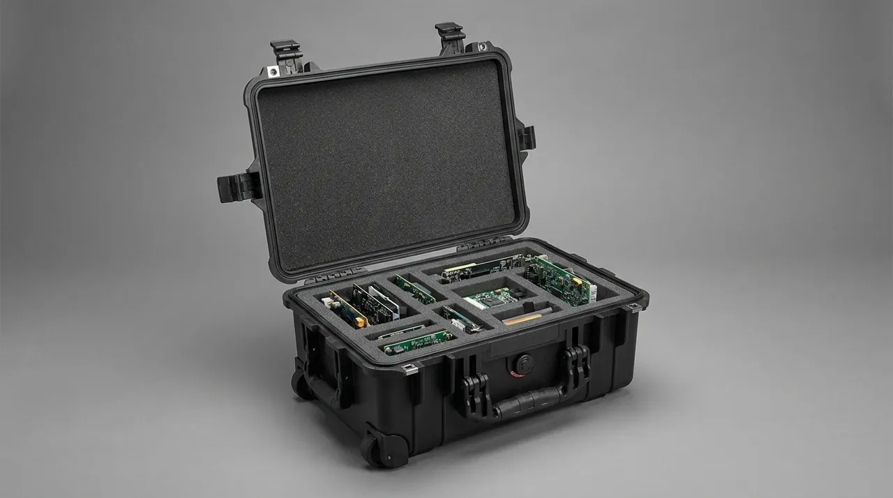
For modules that will be assembled on site, bind the state of charge record, the insulation test record and the case serial number into one continuous file from factory to cabinet. The same discipline is used in data centre and substation projects.
Structural restraint for modules and racks
Battery modules tend to be heavy, geometrically regular and capable of hidden internal damage, so the structural priorities are limiting degrees of freedom and avoiding local stress concentration.
Continuous base support. Support the module base continuously or on a dense point grid. Supporting only the four corners leaves the mid-section unsupported, and that span deforms under vibration and squeezes the cells.
Lateral restraint. Provide a locating structure on all four sides with an allowable lateral movement measured in millimetres, typically within two. A rigid stop combined with a compliant pad gives both restraint and cushioning.
Interlayer separation. When stacking, insert a rigid divider to carry the upper load so the lower module is never compressed directly. Validate the stacking height by test rather than by experience.
Racks and rails. If battery racks, rails or uprights ship with the cells, pack them in an independent zone with sufficient insulation distance and mechanical separation so a structural part cannot fall onto cells in transit.
Removable partitioning. When a batch contains several module sizes, a reconfigurable partition scheme along the lines of a removable divider system covers different footprints and reduces dedicated tooling. For stable, high-volume models a conforming liner built to the module outline is better; the moulding route is described in custom foam insert processing.
Holding insulation performance and re-measuring it
Insulation is the lifeline of a battery system, and transport is the phase in which it degrades most easily. Degradation has three main causes: insulation parts scored or crushed, insulation distance compressed by movement, and moisture or conductive contamination bridging a surface.
At design stage, set insulation distance and creepage distance from the system voltage class and add a margin for transport movement. The insulating barrier must still cover the conductor projection in the worst-case displaced position. Do not use materials inside the case that generate conductive debris.
At material stage, confirm the withstand voltage, temperature range and flame rating of insulating parts. For the low-voltage switching and protection devices used in UPS and energy storage cabinets, selection may reference GB/T 14048 for low-voltage switchgear and controlgear. Flame performance of enclosures and insulating parts is commonly expressed using UL94 classifications.
At goods-in stage, re-measure insulation resistance to the system requirement and record ambient temperature and humidity. If a reading approaches the limit, investigate moisture first rather than declaring the part faulty. High-voltage systems also require a dielectric withstand test under the applicable procedure. Test equipment and lead connection should follow insulation and static control work rules; the working environment is described in ESD shielding case.
| Degradation cause | Symptom | Prevention | Re-measurement |
|---|---|---|---|
| --- | --- | --- | --- |
| Scored or crushed insulation | Local whitening, cracking | Edge chamfers, avoid rigid point loading | Visual plus insulation resistance |
| Compressed clearance | Contact with metal parts | Restraint, displacement margin | Dimensional check |
| Moisture bridging | Surface condensation | Desiccant, sealed packaging | Insulation resistance plus humidity log |
| Conductive contamination | Dust and debris on surfaces | Clean liner, no metal swarf | Visual plus wipe |
Static control and electrochemical corrosion
A UPS battery system contains BMS acquisition boards, communication modules and protection circuits, all sensitive to electrostatic discharge. At the same time, its metal parts are typically copper, aluminium and nickel plated, exposed to electrochemical corrosion wherever moisture meets a potential difference. The two problems frequently appear together.
Three practices cover static control: a dissipative liner with controlled surface resistance, typically in the 10^4 to 10^11 ohm range; a grounding tab inside the case so the unpacking station can be bonded; and dissipative sleeves over exposed sensing harness connectors. Where a project requires it, build the packing and unpacking work instructions around the principles of ANSI/ESD S20.20.
Corrosion control is about breaking the electrolyte path. Keep moisture-absorbing materials from staying wet for long periods, avoid paper or wood filler that can release acids, add insulating separation between dissimilar metals, and let parts stand in a ventilated dry area before racking.
One caution applies to metallised antistatic bags. Their static performance is excellent, but once the metal layer is torn or creased into a sharp edge it can become an unintended conductive path. For battery parts, dissipative packaging is generally preferable to shielding packaging, and the material must be confirmed not to bridge terminals accidentally.
Temperature window and thermal management
Battery performance and safety both depend strongly on temperature. Transport temperature management has two objectives: staying inside the permitted window and avoiding severe thermal cycling.
Temperature window. Take the transport temperature range from the cell or battery maker and mark it on the outer case. Where a route crosses very hot or very cold regions, assess whether insulation or thermal buffering is needed.
Thermal cycling. Repeated cycling accelerates condensation and material ageing. The treatment of low-temperature embrittlement and high-temperature softening in protective cases for extreme temperatures is a useful reference when choosing liner and seal materials that hold performance across the target range.
Thermal isolation. Where cells from different batches or new and used modules share a case, account for different heat generation so an abnormally warm item does not influence its neighbour.
Temperature recording. For long-distance or high-value shipments, place a temperature recording label inside the case, read it at goods-in and file the result. That record is key evidence in any performance dispute.
Boundary of thermal runaway. Be explicit that a protective case cannot stop thermal runaway originating from a cell defect. Its role is to reduce the probability of initiation by mechanical damage, external short circuit and static discharge. Any packaging claim of preventing thermal runaway should be treated with suspicion.
Liner and enclosure material selection
Battery parts place different demands on the liner than liquid-cooling parts do: insulation comes first, cushioning second, with shedding and static accumulation controlled throughout.
| Material option | Insulation | Cushioning | Static control | Typical location |
|---|---|---|---|---|
| --- | --- | --- | --- | --- |
| XPE polyethylene liner | Good | Medium to high | Requires dissipative coating | Module base and load layer |
| Moulded EVA liner | Good | Medium | Can be made dissipative | Cell pockets, precision locating |
| EPP moulded part | Good | High energy absorption | Requires dissipative treatment | Heavy modules, repeat trips |
| Phenolic or epoxy board | Excellent | None | Not applicable | Interlayer and module barriers |
| Ordinary open-cell sponge | Poor, absorbs moisture | Low | Accumulates charge | Not for energised parts |
For the enclosure, the selection drivers are flame rating and temperature resistance. A polymer enclosure needs a confirmed flame class and heat deflection temperature, while a metal enclosure requires internal insulation so that the shell can never become conductive to a live part. If a metal shell is unavoidable, fit an insulating inner liner and design a reliable earth path for the shell.
For assets that circulate repeatedly, design for a long-life shell with a replaceable liner. The amortisation logic for tooling is set out in custom case mould cost analysis, and it is worth comparing against the realistic number of trips rather than the purchase price alone.
Ingress protection, environmental testing and regulatory references
An IP rating answers a dust and water question. IEC 60529, mirrored by GB/T 4208, defines the two digits, the first for solid objects and the second for liquids. The common misjudgement in battery packaging is assuming higher is always better.
The sealing grade is strongly coupled to state of charge and mode of carriage. A tighter seal makes internal pressure more sensitive to temperature and requires a pressure balance provision, while moisture trapped inside a sealed case accelerates corrosion. Set the grade from transport conditions instead of defaulting to the maximum. The selection logic is described in choosing an IP rating for a waterproof case and the practical limits in IP67 protective case boundaries.
| Transport condition | Suggested grade | Additional requirement | State of charge note |
|---|---|---|---|
| --- | --- | --- | --- |
| In-plant transfer | Around IP54 | Dust and insulation focus | Per internal procedure |
| Full truckload road | IP55 to IP65 | Insulating barriers and restraint | Observe road limits |
| Full container sea freight | IP65 to IP67 | Salt mist treatment, desiccant | Check IMDG conditions |
| Air freight | Per applicable rules | Reinforced insulation and marking | Usually most restrictive |
For environment and transport validation, use an ISTA procedure, an ASTM D4169 distribution cycle or the GB/T 4857 series for drop, vibration, stacking and impact. The sequences are set out in ISTA transport testing procedure and GB/T 4857 transport packaging testing. MIL-STD-810H methods may be cited as an environmental test basis, with the explicit note that they represent test methods only and do not constitute any military certification.
Goods-in inspection, storage and racking handover
Goods-in is the last gate before risk reaches the rack. Work through the following sequence and file the results against the case serial number.
Step one, appearance and marking: check the outer case for damage, read the tilt and impact indicators, and confirm dangerous goods markings and documents are complete.
Step two, acclimatisation: set the standing time from the temperature difference between store and transport route, so condensation does not form on a cold part.
Step three, first opening: open the case in a ventilated, dry area free of conductive dust, with operators wearing a wrist strap and using insulated tools.
Step four, detailed inspection: confirm terminal boots are in place, check for swelling or deformation, look for burn marks and odour, and verify that insulating barriers have not shifted. Swelling and abnormal odour are strong signals that require immediate quarantine.
Step five, insulation re-measurement: measure insulation resistance to the system requirement and record temperature and humidity, adding a dielectric and connection resistance test where specified.
Step six, storage and racking: rack conforming parts on a first-in-first-out basis, inspect long-stored parts periodically for voltage and appearance, and quarantine non-conforming parts with the whole packaging batch traceable.
Custom development and volume supply capability
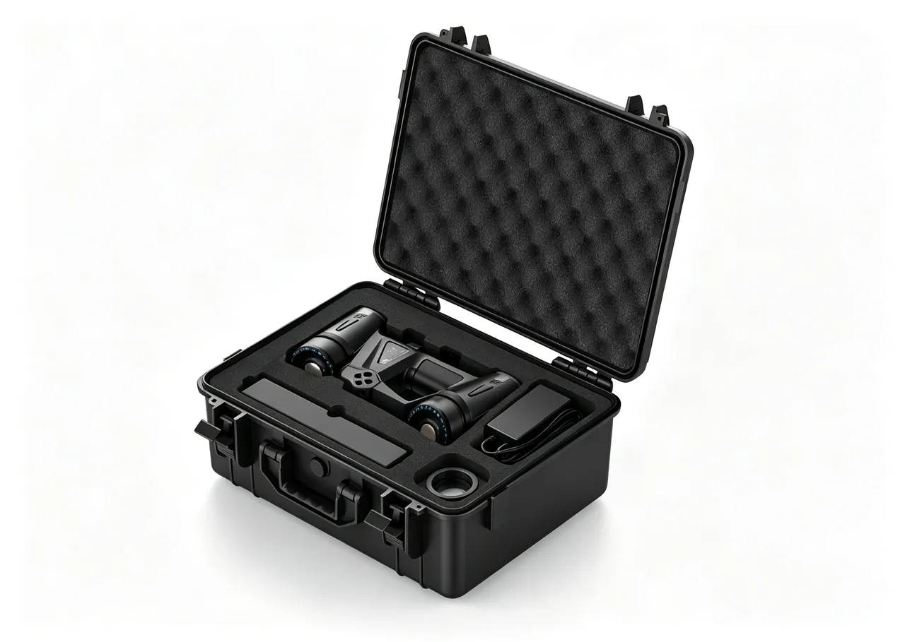
Battery part specifications iterate quickly, so the packaging concept must stay adjustable. Taking UPS and energy storage battery component cases as the example, production and delivery are handled by Kexin New Materials (Guangdong) Co., Ltd., which supplies through wholesale orders, agency channels and export contracts, develops OEM/ODM solutions from customer drawings, 3D models or physical samples, and can release material declarations, assembly records and factory inspection documents with each batch under contract. For energised components the most valuable custom capability is insulated zoning built around the actual terminal layout and module dimensions, because that determines whether insulation work has to be redone on arrival.
Send the following when requesting a quotation: cell or module model, quantity, unit weight and total mass; overall size and terminal positions; permitted shipping state of charge; mode of carriage and destination; insulation and flame requirements; and the regulatory documents and inspection records needed. Complete inputs greatly improve the chance of a one-pass design. A general framework for assessing suppliers is in how to choose a case OEM factory, and the selection of matched parts such as seals is covered in case seal material comparison.
FAQ
Q: Can a UPS battery module be shipped in an ordinary wooden crate with foam?
A: Not advisable unless the crate has been specifically modified. Wood brings three problems: it can release acidic substances, its staples and latches are metal conductors, and its inner faces have no insulation treatment. Foam adds poor static control and no absorbency. If wood is unavoidable, make at least four changes. Replace the liner with a dissipative material or add a dissipative inner tray. Wrap every internal metal part in insulation. Fit an insulating boot to each terminal. And install an insulating barrier with the module positively restrained. Even then, validate the finished package with drop, vibration and stacking testing, and add insulation resistance re-measurement to the goods-in procedure. For high state of charge or large capacity modules, choose a purpose-built structural case instead. Whichever route you take, run the first shipment as a validation batch and inspect it fully rather than by sample, so the decision to proceed rests on evidence from your own supply chain.
Q: Can packaging actually prevent a battery short circuit?
A: It substantially reduces the probability but does not replace the safety design of the battery itself. Packaging controls external short circuit paths: insulating boots stop a metal object bridging terminals, barriers stop modules touching each other or the case wall, and clearing loose metal removes internal conductors. It cannot prevent internal short circuits caused by cell defects, manufacturing faults or electrolyte leakage. The accurate statement is therefore that packaging reduces the probability of external short circuit and mechanical damage initiation, not that packaging prevents short circuits. In commercial projects that distinction affects liability, so state the functional boundary of the packaging in the technical agreement. It is also worth separating an external short circuit from a loose connection. A loose terminal heats up gradually and may show as discolouration, whereas an external short circuit happens instantly and usually leaves a clear burn mark. Both matter, but only the second is directly addressed by terminal insulation and separation.
Q: What state of charge should be specified for shipping?
A: Use the range recommended by the cell or battery maker and satisfy the upper limit set by the applicable transport rules at the same time. The higher the state of charge, the more violent the energy release after a short circuit or mechanical damage, which is why most rules trend toward a lower value and air freight is usually the strictest. In practice, write the range, the measurement method and the measurement point into the shipping specification and mark them on the outer case and documents. Link state of charge to packaging strength as well: if a customer requires a higher state of charge, raise the impact and separation requirements and increase the severity of the transport test program. For projects with repeat shipments, fix the value instead of adjusting it per order, because a stable state of charge makes the packing validation and the carrier paperwork repeatable and far easier to audit.
Q: Under what conditions should insulation resistance be re-measured?
A: Measure in a controlled environment and record temperature and relative humidity at the same time, because insulation resistance is extremely sensitive to moisture. If a part has just come out of a cold environment, let it stand until it approaches ambient temperature, otherwise surface condensation will depress the reading. The instrument and leads must suit the voltage class and the terminals must be clean. If a reading approaches the limit, the first step is to investigate moisture or conductive dust bridging rather than declaring a fault, then dry the part and repeat under identical conditions. High-voltage systems also require a dielectric test performed by qualified personnel, with raw data retained. Keep in mind that a reading taken immediately after unpacking a cold case is the least reliable of all, so plan the receiving schedule to let the part reach ambient conditions before measuring rather than after. Recording the same measurement before dispatch provides a comparison point, and that comparison is usually what shows whether the transport leg or the storage leg caused any change.
Q: What should be done if a tilt or impact indicator has triggered?
A: Quarantine the whole case immediately and do not rack any part from it. Photograph the indicator and the outer case to preserve evidence. Then open the case in the quarantine area and inspect for shell deformation or swelling, displaced terminal boots, shifted insulating barriers, odour and burn marks. Next, carry out insulation resistance measurement and any required electrical tests, and widen sampling across the same batch and pallet. On that basis decide between rework, downgrading or scrapping, and notify the carrier and insurer in parallel. No part from that case should be broken out into normal stock until the disposition is signed off. The quarantine should cover the packaging as well. Keep the case, liner and indicator labels together with the parts until the disposition is signed off, because liner impressions and label state are part of the evidence. Releasing the case early, or reusing it for another shipment, destroys the record the investigation depends on.
Q: Should the BMS acquisition board be packed separately?
A: Yes, and separated from the cell zone. The board is static sensitive and its harness connectors are prone to tension under vibration. Pack it in a dissipative package in its own location, coil the harness to the minimum bend radius and secure it, and cap the connectors. If the board travels in the same case as the module, ensure it never touches metal, never carries module weight and cannot be pulled by module movement. Mark the bend radius and fixing points in the packaging drawing, and check the harness for stretched or broken conductors during unpacking. One further point applies when the board ships fitted to a module rather than on its own: neither the module edge nor the board edge may become a load path. If the board is trapped between the module and the case wall, any lateral movement in transit goes straight into the board, so the cavity should be sized so the module meets the liner and the board does not.
Q: Why is metallised antistatic bagging discouraged?
A: A metallised bag works by forming a shield, so its static performance is often excellent, but it holds one hidden risk for energised battery parts. Once the bag is torn or creased into a sharp metal edge, that layer can become an unintended conductive path bridging terminals or a module shell. Dissipative materials with controlled surface resistance suit battery parts better: they bleed charge away slowly instead of forming a shielding conductor, and they do not create conductive points when damaged. If shielding is genuinely required, confirm the package is a composite with inner and outer insulation, avoid metal tools during unpacking, and ensure the work area has a grounding provision. A compromise used on some projects is an inner dissipative liner with an outer moisture barrier, which keeps the charge path controlled while still limiting humidity. Confirm the combination with the coolant and the battery maker before adopting it, because a barrier film traps moisture if the part is packed damp.
Q: What matters for battery parts held in long-term storage?
A: Temperature, humidity and state of charge are the three governing factors. Keep the desiccant inside the case effective and inspect or replace it on a schedule. Hold store temperature steady so day and night swings do not cause condensation inside the case. Check voltage periodically as recommended by the maker and top up charge where required. Choose a case that opens and closes repeatedly without destroying the seal each time, and keep a traceable inspection record. If a liner deforms after many open and close cycles, replace it, because a deformed liner loses its restraining function and lets the module shift during handling. Where traceability is required, record the case serial number, inspection date and inspector together. Where one warehouse holds both new and returned parts, keep them physically separate. Returned parts may carry a different state of charge, a different history and sometimes undetected damage, and mixing them into the same packaging pool makes traceability almost impossible to reconstruct later.
Conclusion and further reading
The hard part of battery packaging is not making the case stronger; it is controlling the electrical nature of what goes inside. Terminal insulation, state of charge, insulation distance and temperature window are the four items that matter, and losing any one of them turns a structurally excellent case into ineffective packaging. Before the next UPS or energy storage shipment leaves the plant, run an internal self-check against the tables above, close the gaps, and only then discuss cost reduction.
Further reading