

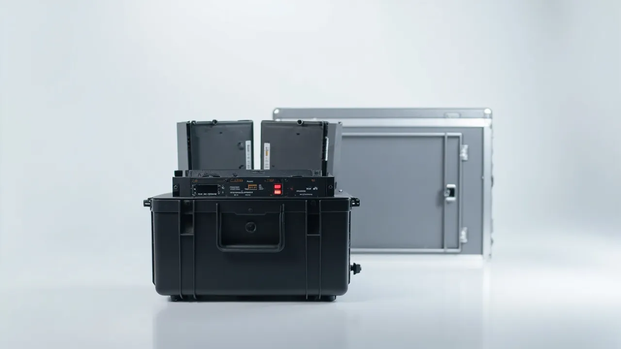
Once a data hall moves from air cooling to liquid cooling, the CDU (coolant distribution unit) and the cold plate stop being metal blocks that can be wrapped in film and shipped. Their failure modes shift from simple mechanical impact to particulate contamination, residual fluid leakage, scratched quick-disconnect sealing faces and electrochemical corrosion. Those defects are usually invisible at the moment of unpacking, yet they surface weeks later as abnormal flow rates, weeping joints or degraded heat transfer, at a point where the data hall has almost no service window. A case built for liquid-cooling parts therefore has to solve three things at once: cleanliness, leak containment and dimensional stability.
This guide is written for infrastructure contractors, liquid-cooling equipment builders and data hall integrators. It breaks down the transport risks of CDUs, cold plates, quick disconnects and hose assemblies, and gives executable practices for foam selection, sealing grade, test validation and incoming inspection. It also explains how JUNZHJIA supports non-standard custom packaging of this kind. You can lift the checklists straight into an RFQ package and an incoming inspection procedure.
Contents
- Why liquid cooling demands a dedicated component case
- CDU transport risk map: cleanliness, leakage, pressure and vibration
- Cold plates and quick disconnects: sealing faces and microchannels
- Cleanliness control: particles, ionic residue and outgassing
- Leak containment: secondary sealing, absorbent layers and orientation
- Vibration and impact structure: case stiffness and foam restraint
- Dual protection against ESD and electrochemical corrosion
- Foam material comparison
- Sealing and ingress protection grades under IEC 60529
- Temperature and humidity management, and the condensation trap
- Transport testing and packaging validation
- Unpacking, acclimatisation and handover to installation
- Incoming inspection checklist and custom supply capability
- FAQ
- Conclusion and further reading
Why liquid cooling demands a dedicated component case
In an air-cooled rack, fans and heatsinks are low-value items that can be swapped on failure, so packaging cost can be squeezed hard. A liquid-cooling loop is a different animal. A single CDU integrates a brazed plate heat exchanger, circulation pumps, flow meters, filters, differential-pressure sensors and dozens of quick disconnects, while a cold plate is bonded directly to a GPU or CPU, where surface finish and channel geometry set the thermal resistance. A scratch measured in microns or a lodged particle can escalate into a whole-rack throttling event or an outage, and the cost of that event is not on the same scale as the packaging it would have taken to prevent it.
From a procurement standpoint, the value of a purpose-built cooling component case is not "it is stronger". It is three measurable capabilities: the cleanliness achieved at the factory survives until commissioning; residual fluid in transit does not contaminate the case or neighbouring parts; and critical mating dimensions do not drift under vibration and stacking. All three can be locked down through material selection, structural design and test validation, rather than by adding another layer of bubble wrap.
By contrast, a generic plywood crate lined with polyethylene foam has three predictable gaps. The foam itself sheds debris and offers no static control. The inside faces have no absorbent provision, so any fluid weeping from a CDU collects at the bottom and spreads. And there is no locating structure, so cold plates slide freely and quick disconnects knock against each other. The direction of improvement is clear, but it has to be rebuilt around liquid-cooling logic instead of inherited from whole-machine packaging habits. Several of the cleanliness and static requirements overlap with cleanroom equipment packaging, described in the notes on cleanroom clean packaging practice.
CDU transport risk map: cleanliness, leakage, pressure and vibration
Splitting the problem into four risk families makes it easier to map each one to a design measure and an inspection metric.
Cleanliness risk. A CDU is normally flushed and capped before dispatch. If the foam sheds or the case interior is dusty, particles settle on heat exchanger ports and filters and are carried into the loop at first fill. Typical control targets are a non-shedding liner, no free particles inside the case, and port caps in place.
Leakage risk. Residual water or glycol solution thickens and contracts at low temperature, then expands in a warm leg, so fluid creeps past quick-disconnect caps. If it is not absorbed, it runs along the case floor and attacks metal surfaces.
Pressure risk. Trapped air in a closed case body fluctuates with temperature. Without a pressure-equalisation provision the seals see repeated positive and negative cycles. The selection logic for balance elements is covered in pressure equalisation valve configuration, and the underlying point is that a tighter seal is not automatically a safer one.
Vibration and impact risk. Cantilevered masses such as pumps and plate exchangers amplify displacement near resonance, while repeated handling concentrates drop energy at corners and edges. The countermeasures are restraint, higher case stiffness and a stated stacking limit.
| Risk family | Typical trigger | Primary countermeasure | Inspectable metric |
|---|---|---|---|
| --- | --- | --- | --- |
| Cleanliness | Foam shedding, dusty interior | Closed-cell liner, clean assembly | No shedding, caps in place |
| Leakage | Residual fluid, thermal expansion | Absorbent layer, double seal, orientation | No stains, no residue traces |
| Pressure | Air pressure swings in closed cavity | Balance valve or controlled venting | No deformed seal faces |
| Vibration and impact | Resonance, handling drops | Restrained liner, stiff shell | Key dimensions within tolerance |
Cold plates and quick disconnects: sealing faces and microchannels
The cold plate is the most surface-sensitive item in the loop. Once a hard particle scratches the machined microchannels, weld faces or mounting faces of a copper or aluminium body, the local rise in thermal resistance is rarely recoverable downstream. The protection rule is straightforward: metal should touch only a soft, clean liner that does not migrate plasticiser, and it must not move a second time under any transport orientation.
Quick disconnects concentrate the problem on sealing faces. UQD-style couplings rely on a precise axial compression of the poppet and O-ring. If they knock against each other inside the case, a scored sealing face typically shows up as a joint that is dry at rest but weeps under pressure. Give each coupling its own location, leave the caps installed, add a protective sleeve where needed, and never stack couplings directly on top of one another.
Hose assemblies have a bend radius problem of their own. Forcing a tight radius leaves a permanent crease in the braid, which becomes a local flow restriction. Transport positions should follow the manufacturer's minimum bend radius using curved channels, and a removable divider system is a practical way to partition loops, as described in removable divider system design.
For mixed-model shipments, print a component location diagram on the inside of the lid and number the foam pockets. Unpacking staff can then check against the diagram and avoid the classic errors of a missing part, a duplicate part or a part in the wrong pocket.
Cleanliness control: particles, ionic residue and outgassing
Cleanliness requirements in a liquid loop come from two directions. Particles block microchannels and filters. Ionic residue and outgassing change coolant conductivity and, over time, drive corrosion and deposition. Packaging can influence three control points.
The first is the liner material itself. Closed-cell materials such as XPE and EVA carry far lower shedding and outgassing risk than open-cell sponge, provided the formulation avoids migratory plasticisers and halogenated flame retardants. If a customer sets an extractable-ion limit, ask for a material declaration rather than accepting a claim that the plant is "cleanroom based".
The second is the cleanliness class of the assembly area. Cutting, bonding and kitting set the initial particle baseline inside the case. Requiring a stated assembly-area class is more auditable than requiring a general promise of cleanliness.
The third is port capping and internal covering. Every fluid port should be capped before the part goes in, and a clean PE bag can be draped over the assembly as a whole, with the caveat that the film must be slip-agent free.

For projects with quantified cleanliness targets, the approach described in cleanroom equipment component cases can be carried over: write the cleanliness metric into the technical agreement and agree an on-site sampling method, such as visual inspection plus a wipe-cloth comparison that a receiving inspector can actually perform.
Leak containment: secondary sealing, absorbent layers and orientation
The goal of leak containment is not "zero leakage". It is "if it leaks, it does not spread and does not penetrate". That calls for a layered design.
Port layer. Cap every quick disconnect and pipe end, and where necessary add a second wrap of film or a heat-shrink sleeve as the first barrier.
Absorption layer. Place an absorbent material along the case floor and the base of the liner to take up any fluid that escapes. Size the absorbent capacity against the worst-case residual volume of a single component, not against a few drops. The absorbent layer also adds cushioning.
Isolation layer. A coolant-resistant membrane or inner tray keeps fluid away from the case wall and from adjacent parts. If the coolant contains glycol, confirm long-term compatibility of the isolation material.
Orientation layer. State the transport orientation explicitly, usually ports up or as specified by the manufacturer, and apply an irreversible tilt indicator to the outside of the case so the receiving party can see whether it was respected.
| Layer | Implementation | Symptom if it fails | Check method |
|---|---|---|---|
| --- | --- | --- | --- |
| Port | Cap plus secondary wrap | Fluid inside cap | Visual, cap off |
| Absorption | Absorbent mat or pad | Pooling on case floor | Visual plus touch |
| Isolation | Fluid-resistant liner or tray | Wall contamination | Visual plus wipe |
| Orientation | Tilt indicator label | Label triggered | Read at unpacking |
One caution: the absorbent material must not become a new particle source, and it must not produce dust. Evaluate absorbency rate and shedding behaviour together rather than optimising only one of them.
Vibration and impact structure: case stiffness and foam restraint
Liquid-cooling parts are often poorly balanced. A CDU concentrates its pump and plate exchanger on one side, while a cold plate is a thin, large-area plate. The two need different vibration strategies.
For a heavy, off-centre item such as a CDU, the priorities are base support and shell stiffness. The floor must carry the full mass without visible deflection, the liner must give continuous support across the footprint of the centre of gravity, and unsupported spans must be avoided. Shell options include copolymer polypropylene or high-impact engineering plastics with ribbed walls and reinforced edges.
For a thin item such as a cold plate, the priorities are out-of-plane stiffness and restraint. A large flat plate behaves like a drumhead under vibration, and long exposure can fatigue solder joints. The remedy is a conforming pocket liner that constrains both faces rather than foam blocks at the four corners. When stacking several cold plates, put clean interleaving paper between them and cap the stack height.
Where sensors and circuit boards are involved, consider board movement inside its slot. The retention approach used for plug-in cards in servo motion controller cases is a useful reference: restrain the board with insulating pads so it cannot contact the metal housing.
For stacking, mark the maximum number of layers on the outer case and validate it with a stacking test. In practice, three layers is a sensible ceiling for liquid-cooling component cases, and the bottom layer should sit on a reinforced pallet.
Dual protection against ESD and electrochemical corrosion
A CDU and a cold plate are not purely mechanical. A CDU contains control boards, sensors and communication interfaces, and a cold plate often carries a temperature sensor harness. Electrostatic discharge is a hidden threat to these devices: the result is not always immediate failure but parameter drift or latent damage, which appears after commissioning as measurement offset or intermittent communication faults.
Three practical measures cover most of it. Use a dissipative liner with a controlled surface resistance, typically within the 10^4 to 10^11 ohm range. Provide a grounding tab or strap inside the case so the unpacking station can be bonded. Cover exposed connector pins with a conductive or dissipative sleeve. Selection guidance is available in ESD shielding case design, and the same principles align with the packaging expectations of ANSI/ESD S20.20.
Electrochemical corrosion needs three conditions at once: dissimilar metals, an electrolyte, and a potential difference. Liquid-cooling parts supply the first two by nature, so the third must be broken. Do not let residual fluid pool where dissimilar metals meet, do not let the absorbent layer stay wet for long periods, and do not use paper or wood filler that can release acids inside the case. If paper supports are unavoidable, specify a neutral, acid-free grade.
There is a common misconception worth correcting: sealing the part inside a fully closed plastic bag in the name of extra protection. If the surface is still wet, a closed bag creates a humid microclimate that accelerates corrosion. A slightly breathable enclosure, or drying the surface before bagging, is the safer route.
Foam material comparison
The liner contributes most of the protective performance and accounts for most of the cost spread. The table compares common materials against the actual needs of liquid-cooling components; the values are industry experience ranges and the supplier's material declaration governs in each case.
| Material | Density and rebound | Shedding tendency | Absorbency | Best fit |
|---|---|---|---|---|
| --- | --- | --- | --- | --- |
| XPE cross-linked polyethylene | Medium-high, stable rebound | Low | None, pair with absorbent layer | CDU body, heavy bases |
| EVA copolymer | Medium, finely mouldable | Low | None | Cold plate pockets, precision locating |
| PU polyurethane | Low, soft and resilient | Medium | Low | Curved cushioning, odd shapes |
| EPP expanded polypropylene | Low, high energy absorption | Low | None | Reusable cases, repeated trips |
| Open-cell sponge | Low | High | High | Not recommended for clean parts |
Decide in this order: cleanliness and leak containment first, cushioning second. Eliminate any candidate whose shedding or outgassing risk is unacceptable, then compare the survivors on cushioning and cost. Finely moulded EVA suits cold plate pockets, but confirm the formulation has no migratory additives. XPE suits large load-bearing liners and is easy to build into multi-layer composites.
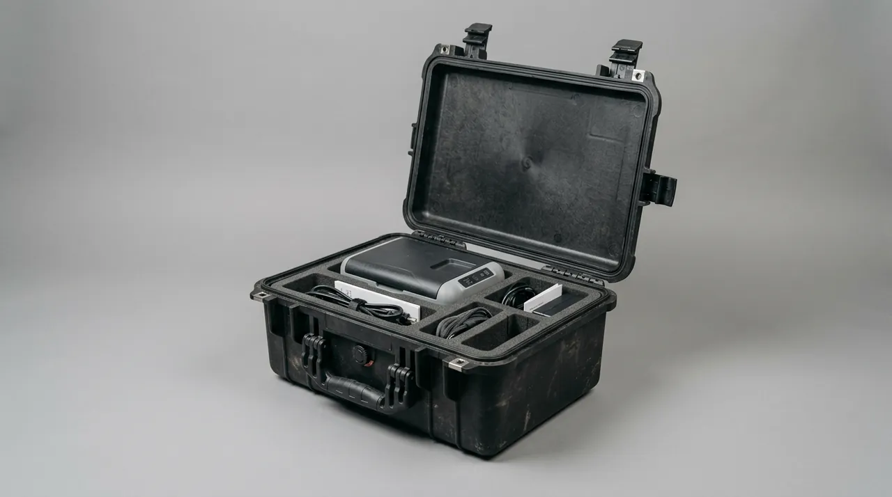
JUNZHJIA typically builds a three-part stack for custom liners: a shell for stiffness and sealing, a structural liner for locating, and a functional layer for absorption, static control or cushioning. Because pipe routing differs enormously between CDU models, supply a physical sample or a 3D model so the liner can be designed around the centre of gravity and port positions instead of a generic template. Details of the moulding process are in custom foam insert processing.
Sealing and ingress protection grades under IEC 60529
Does a liquid-cooling component case need a high IP rating? The answer depends on the transport and storage environment, not on a preference for higher numbers. IP ratings are defined in IEC 60529, with the first digit covering solid objects and the second covering liquids.
A fully sealed design such as IP67 carries a side effect: internal air pressure cannot equalise with temperature and altitude changes, so seals see repeated stress, the case can be hard to open, and pressure eventually escapes at the weakest point. A highly sealed case should therefore be paired with a pressure equalisation element rather than chasing a perfect water barrier. See the guidance on choosing an IP rating for a waterproof case and the practical limits described in IP67 protective case boundaries.
| Transport and storage condition | Suggested protection | Additional requirement |
|---|---|---|
| --- | --- | --- |
| In-plant transfer, climate-controlled store | Around IP54 | Dust focused, light sealing |
| Long-haul road, ordinary warehouse | IP55 to IP65 | Absorbent layer plus pressure balance |
| Sea freight, cross-border intermodal | IP65 to IP67 | Salt-mist treatment, desiccant |
| Outdoor staging, site delivery | IP66 to IP67 | UV resistance, anti-condensation |
Remember that an IP rating describes only the enclosure's resistance to dust and water ingress; it is not a statement about transport reliability. Real transport reliability is demonstrated by a packaging test such as ISTA or ASTM D4169, covered in the next section. Sealing materials must also be compatible with cleaning agents, disinfectants and the coolant itself, so that they do not harden or crack after prolonged contact. For seal selection see case seal material comparison.
Temperature and humidity management, and the condensation trap
Liquid-cooling components are less humidity-sensitive than complete electronics, but condensation still matters. The classic scenario is a winter shipment from a cold warehouse into a warm data hall, or a summer shipment from an air-conditioned workshop to a hot outdoor staging area. The case interior lags the outside temperature, so any moisture inside condenses on the cooler metal surfaces.
There are four levers. First, control the packing dew point, ideally packing in a low-humidity area and drying the liner and absorbent layer where necessary. Second, use a correctly sized desiccant, calculated from free volume inside the case rather than by rule of thumb, positioned so it never touches metal parts and confirmed not to release corrosive vapour. Third, define an acclimatisation period before unpacking, for example a few hours when the temperature difference exceeds 15 degrees Celsius, so the case reaches ambient equilibrium. Fourth, consider a breathable design such as a vented membrane that lets water vapour escape slowly while blocking liquid water; if a desiccant is used alongside it, balance the two so the desiccant does not saturate prematurely.
For projects that stage equipment in extreme cold or heat, the treatment of low-temperature embrittlement and high-temperature softening described in protective cases for extreme temperatures is relevant. These conditions are also frequently referenced through MIL-STD-810H environmental test methods. Note clearly that MIL-STD-810H is cited here only as a test-method reference and does not constitute, imply or represent any military certification.
Transport testing and packaging validation
A packaging design should be validated before release, not judged by how sturdy it looks. Three test systems cover most needs.
ISTA series. Simulates parcel, less-than-truckload and full-truckload distribution, so the correct procedure follows the actual channel. The sequence is described in ISTA transport testing procedure.
ASTM D4169. Uses a distribution cycle framework and allows a test sequence assembled from the real shipping chain, which suits cross-border intermodal projects. See ASTM D4169 distribution cycle testing.
GB/T 4857 series. The general Chinese test methods for transport packaging, covering stacking, vibration, drop and impact. See GB/T 4857 transport packaging testing.
Three things must be settled before testing: whether the sample is representative, including a mass dummy that matches the real load; what the pass criteria are; and which measurements are repeated after the test. For liquid-cooling parts, the recommended criteria include no scoring on quick-disconnect sealing faces, no out-of-tolerance flatness on cold plate mounting faces, no permanent creases in hoses, and no visible pooling inside the case.
Where MIL-STD-810H methods are cited, the report should state that they are used as test-method references only and that no military certification is claimed.
Unpacking, acclimatisation and handover to installation
A case only delivers its value at the moment of unpacking. If the receiving process is casual, the earlier design and validation work can be undone in ten minutes. Follow this order.
Step one, exterior check: record the case condition, tilt indicator status, seal integrity and outer markings. This step is the basis for any later liability discussion.
Step two, acclimatisation: allow the standing time defined earlier, extended when the temperature difference is large.
Step three, surface check: with the port caps still on, look for deformation, leakage traces and water marks.
Step four, cleanliness check: in a controlled area, remove the inner wrapping and inspect the liner for shedding and the absorbent layer for saturation.
Step five, component check: verify quantities, part numbers and positions against the diagram, then inspect quick-disconnect sealing faces, cold plate mounting faces and pipe ends.
Step six, record and trace: photograph the findings and log the link between case serial number and component serial numbers for later quality tracing.

The point of this sequence is to move discovery as early as possible. A problem found inside the case is the cheapest to fix; a problem found after the part is on the rack is the most expensive. Write the unpacking inspection into the work instruction, and state clearly who is authorised to reject a shipment and how a suspect case is quarantined.
Incoming inspection checklist and custom supply capability
The following table condenses the earlier points into a checklist that can be used directly at goods-in.
| Check item | Acceptance requirement | Record |
|---|---|---|
| --- | --- | --- |
| Case exterior | No through damage, no severe corner deformation | Photo plus note |
| Tilt indicator | Not triggered | Photo |
| Sealing | Gasket attached, no gap when closed | Visual and feel |
| Liner | No shedding, no damage, no oil marks | Visual |
| Absorbent layer | Dry, no discolouration, no pooling | Visual and touch |
| Port caps | All present and tight | Count each item |
| Component count | Matches packing list | Count and sign |
| Critical mating faces | No scratch, dent or rust stain | Visual plus magnifier |
| Markings | Model, serial and orientation arrows legible | Visual |
Beyond inspection, procurement should assess the supplier's customisation and delivery capability, particularly for non-standard sizes, mixed packing lists and document packages. Taking liquid-cooling component cases as the example, manufacturing is carried out by Kexin New Materials (Guangdong) Co., Ltd., which serves buyers through volume supply, regional agency arrangements and cross-border shipping, develops OEM/ODM solutions from drawings or physical samples, and can contractually release material declarations, assembly records and factory inspection documents with each batch. For a liquid-cooling project the single most valuable capability is a liner built around the actual port layout, because that is what determines whether parts need re-cleaning after transport.
For a quotation, supply at least the following: the component list with weights, overall dimensions and centre of gravity, port types and whether the unit ships wet, transport mode and stacking limit, cleanliness and ESD requirements, and the document set required. The more complete the input, the closer the first proposal comes to a one-pass design. Broader guidance on vetting a manufacturer is in how to choose a case OEM factory.
FAQ
Q: Can a CDU and cold plates share one protective case?
A: They can, but not mixed without separation. A CDU is a heavy, off-centre item that needs a continuous load-bearing base, while a cold plate is a thin precision part that needs conforming pockets and interleaving paper. If they share a case, place the CDU in the lower section with its own restraint, put cold plates in an independent upper zone, and add a rigid divider so a local high point on the CDU cannot press into a cold plate. Every quick disconnect must be capped and must never touch a cold plate surface. Also review the combined mass distribution, because a shifted centre of gravity makes the case unstable during handling. When there are many combinations, a removable divider system lets you reconfigure by shipment instead of tooling a foam insert for every possible mix. Whichever arrangement you choose, write it into the packaging drawing so the same logic is repeated on every shipment, and re-check the mass balance whenever a component changes. On a large deployment, keep one spare case configured for the dominant CDU model so that a single damaged unit can be repacked at the factory without waiting for new foam.
Q: Why is ordinary polyethylene foam not recommended for liquid-cooling components?
A: Two reasons dominate: shedding and absorbency. Polyethylene foam produces debris after cutting and repeated compression, and that debris is exactly the particulate contamination a liquid loop cannot tolerate. Once carried into a heat exchanger or filter, the clean-up cost far exceeds the packaging saving. Second, the material does not absorb liquid, so any fluid weeping from a quick disconnect runs along the case floor and attacks adjacent metal surfaces. Third, ordinary grades are open-cell and hold moisture for long periods, which creates the conditions for electrochemical corrosion. If cost forces its use, restrict it to outer cushioning, keep it away from direct contact with parts, and add both an absorbent layer and a clean inner membrane as barriers. Where cost forces its use, treat it as a short-term compromise: re-validate the case for shedding and absorbency before the first shipment, and expect to replace the liner sooner than with a closed-cell material. Also confirm that the case interior is free of loose foam particles before the CDU goes in, because a single crumb that reaches a filter can cost more to remove than the packaging saved.
Q: Does the case have to be rated IP67?
A: Not automatically. An IP rating addresses dust and water ingress, while the real risks for liquid-cooling parts are vibration, impact and residual fluid management. For in-plant transfers and climate-controlled storage, a dust-focused design around IP54 is usually sufficient. Only sea freight, cross-border intermodal transport or outdoor staging justify IP65 to IP67. Note also that in a fully closed case internal air pressure varies with temperature and altitude, so a pressure equalisation element is required; otherwise the seals see repeated stress and fail earlier. The correct order is therefore to set the grade from the environment first, then add the balance and absorbency provisions that the grade implies. A useful test is to ask what would happen if the case were opened in a rainstorm at a site with no shelter. If the contents would still be acceptable, the grade is probably right; if not, the environment has been underrated and the grade should move up. Record the reasoning alongside the packaging drawing so the choice can be reviewed later. Whichever grade is selected, state it on the drawing and on the case label so that the choice stays visible to the receiving team.
Q: Should desiccant be used, and how much?
A: It depends on the packing humidity and the temperature and humidity swing in transit. If packing is done in a low-humidity area with an inner membrane, little or none is needed. Sea freight or routes with large temperature swings justify a calculated amount. Size it from the free volume inside the case using the sorption curve of the specific desiccant, rather than adding a few sachets by feel. Position it away from metal parts and sealing faces, for example fixed to the inside of the lid in a breathable bag. Assess compatibility with the coolant so that no desiccant dust reaches the fluid path. If a breathable vented membrane is used at the same time, expect the desiccant to saturate earlier, and define a replacement interval accordingly. Whichever quantity is chosen, treat the calculation as an assumption to be verified: check the first shipment against the indicator reading, and only then pack the volume order the same way. A further practical point is to buy desiccant in sealed sachets with a printed date rather than loose material, since a part-used bag absorbs moisture in the store and gives a false sense of protection once it is packed.
Q: What should be re-measured on a cold plate after transport?
A: At least three groups of checks. First, the condition of the mounting face, including flatness or any local dents and deformation, because these change interfacial thermal resistance directly. Second, flow path patency, checked with low-pressure gas or a small water flow to confirm there is no blockage. Third, appearance and joints, covering cracks in weld zones, scratches on ports and completeness of markings. If the plate carries a temperature sensor harness, inspect for stretched or broken conductors as well. Bind the re-measurement record to the case serial number so a traceable quality file exists and any later issue can be attributed to transport or to assembly. Where several plates travel together, do not sample only the most accessible one. Take the first and the last out of the case, because a plate's position changes the vibration it sees. Keep the measurement conditions consistent between shipments so trends can be compared over time. It is also worth agreeing a re-measurement format with the customer up front, covering instrument, range, temperature, humidity and the points measured, so that readings from different sites can be compared rather than merely filed. Attach a photograph of the probe placement for each point.
Q: Is ESD protection really relevant for a CDU?
A: Yes, though the concern is not the mechanical body but the internal control board, sensors and communication interfaces. These devices have limited tolerance to electrostatic discharge, and damage does not always cause immediate failure. It can appear as parameter drift, intermittent communication loss or measurement offset, all of which are time-consuming to diagnose in a live data hall. Packaging measures therefore include a dissipative liner with controlled surface resistance, typically in the 10^4 to 10^11 ohm range, plus a structure that allows the case to be bonded to ground. Exposed connector pins should be covered with dissipative sleeves. Where a project requires it, build the packing and unpacking procedure around the principles of ANSI/ESD S20.20 to keep static risk under control. Because the damage is often latent, the return on static control shows up as avoided field failures rather than as visible defects at goods-in, which makes it easy to under-invest in. Treat the liner resistance specification and the grounding provision as part of the electrical specification, not as a packaging detail. Confirm the dissipative liner specification with a surface resistance measurement on the finished case, not on a material sample alone.
Q: How can I tell whether the shipment was tilted or dropped?
A: The most direct method is an irreversible indicator label. A tilt indicator changes colour or shows a flag once a set angle is exceeded, while an impact label triggers above a set acceleration threshold. Both are inexpensive and give a clear basis for attributing responsibility. Fit a tilt indicator on each of two adjacent faces so it cannot be hidden by a single orientation. Apply a tamper seal and a serial number to the outer case, and photograph the indicators before opening. If one has triggered, focus the unpacking inspection on quick-disconnect sealing faces, restraint points of cantilevered parts, and any shifted impressions in the liner, and retain all images as evidence. Some projects add a shock logger that timestamps events, which helps identify where on the route the event happened. For cross-border shipments that record is often the most persuasive evidence available. It is also worth photographing the indicators and the case seal at each transhipment point, not only at the final destination, because the further a claim travels from the event the harder it becomes to attribute. On projects with several carriers, that record is often the only way to establish which leg caused the damage.
Q: What inputs are needed to develop a custom liquid-cooling component case?
A: Five groups are usually enough. The component list with quantities, individual weights and total mass. Overall dimensions and the port layout, ideally as a 3D model or dimensioned photographs. Transport mode and stacking limit, which set the structural strength and the test severity. Environmental and compliance requirements such as cleanliness class, ESD control and whether third-party test reports are needed. And delivery and documentation requirements, including whether batch inspection records ship with the goods. With complete inputs, the usual path is a structural and liner proposal for approval, a validated prototype case, then volume production. When component models change frequently, an adjustable liner improves reuse across versions. One further input is worth supplying if it exists: a photograph of a previously damaged shipment. It usually exposes the failure mode faster than any drawing and lets the supplier design against the specific weakness instead of a general assumption. Where a project uses the same case for several cooling models, ask the supplier to mark each pocket with the component it was cut for, so that a later change of model cannot be mistaken for a packing error.
Q: How do I lower the lifetime cost of these cases?
A: Three directions work well. First, raise the reuse rate by selecting a liner that tolerates repeated compression and by designing a replaceable functional layer, so the shell outlives the liner and only the liner is renewed. Second, cut the number of part numbers by using removable dividers or adjustable locating posts that cover several combinations, avoiding separate tooling per model; tooling amortisation is analysed in the linked cost article. Third, improve the transport plan, for example by reducing stack height or changing handling practice to cut drop probability, which in turn relaxes the strength requirement on the packaging. Taken together, lifetime cost is a better decision basis than the purchase price of a single case. A fourth and less obvious lever is to standardise the outer case across product families and vary only the liner and the internal markings. Shell tooling is the expensive part, and sharing it across several cooling product lines reduces what each line has to carry. A related point is to keep the packaging drawing and the actual liner in step, because a liner that has been trimmed on site loses the dimensional accuracy that the original design depended on.
Conclusion and further reading
Packaging liquid-cooling parts is not a matter of putting something in a box. It is a chain running from cleanliness through leak containment and vibration control to traceability. Write cleanliness, leak containment and dimensional stability into the technical agreement and back them with an executable inspection checklist, and transport risk becomes controllable. For your next quotation request, send the checklists above to every candidate supplier and ask them to quote against the same yardstick; the differences in approach will matter more than the differences in price.
Further reading