

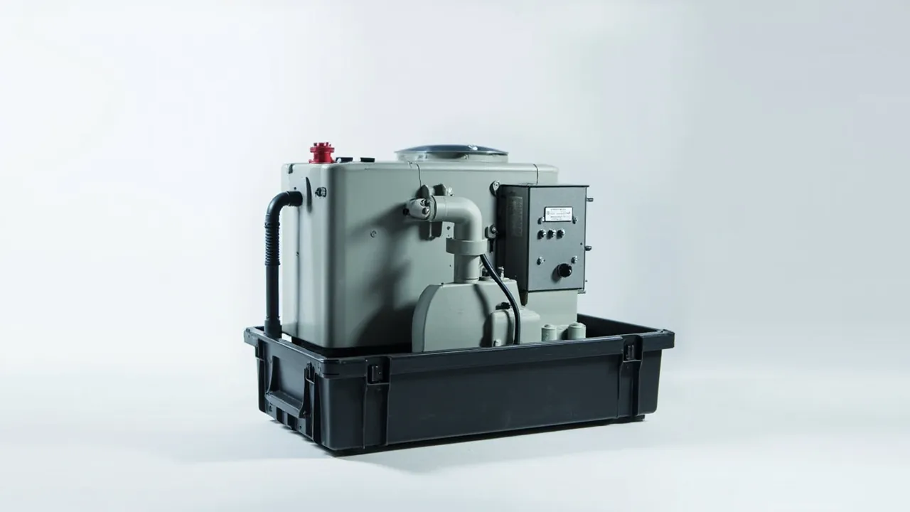
An industrial chiller parts case has to solve a specific problem: keep the compressor, condenser and evaporator — heavy, vibration-sensitive and water-bearing — at their original installation accuracy and heat-transfer capability after the machine has been dismantled for transport. Chiller damage rarely comes from a single violent impact. It comes from prolonged low-frequency vibration and from residual water expanding at low temperature. The design priority is therefore not thicker walls, but breaking the vibration transfer path and draining the water circuits completely.
Field repair data for chiller components clusters tightly. A compressor arrives with deformed mounting feet, collapsed isolation pads and hairline cracks at the suction and discharge connections. Tube bundles in a shell-and-tube exchanger rub against baffles under inertia and lose wall thickness. Brazed plate packs shift laterally and leak internally after reassembly. Water circuits are not blown dry, and bundles split after a winter shipment. None of this is visible at the moment the case is opened; it surfaces in a concentrated burst during commissioning. This guide follows three threads — vibration, water and cleanliness — and ends with a layered protection scheme and an acceptance checklist.
Table of Contents
- The Design Starting Point: Block Vibration Before It Reaches the Compressor
- Component List and Risk Grading
- The Compressor: Anti-Vibration Comes First
- Condensers and Evaporators: Tube Deformation and Freeze Damage
- Plate and Shell-and-Tube Exchangers: Two Different Protection Logics
- Expansion Valves and Filter Driers: The Cleanliness Floor
- Pumps and Flow Switches: Mechanical Seals Hate Dry Running and Knocks
- Control Cabinets and VFD Modules: How to Fix Them Properly
- Case-Level Vibration Control: From Foot Pads to Suspended Inserts
- Freeze and Moisture Control: Draining, Desiccant and Humidity Judgement
- Shell Structure Comparison
- Test Validation: Random Vibration, Stacking and Drop
- Insert Tooling and Batch Consistency
- Frequently Asked Questions
- Conclusion and Further Reading
The Design Starting Point: Block Vibration Before It Reaches the Compressor
Vibration inside a packaging system travels a chain: the vehicle transmits motion to the pallet, the pallet to the case floor, the case floor through the insert to the component, and finally into the weakest feature of that component. Weaken any link and the load at the end of the chain drops measurably.
Three chiller component groups are especially vibration-sensitive, because each has a resonance window. Compressors, particularly scroll and screw types, form cantilever structures through their suction and discharge piping and mounting feet, and they amplify motion in the 10 to 30 Hz band. Brazed plate heat exchangers have low lateral stiffness once plate packs are stacked, so lateral vibration causes fretting between plates. Contactors and relays inside control cabinets develop micro-movement at their contacts under sustained vibration, which raises contact resistance and heat.
Road transport concentrates its energy in the low-frequency band, typically 3 to 15 Hz, while sea freight spreads it more widely. The practical consequence is that simply adding thicker foam does not help a chiller much, because foam provides almost no isolation at low frequency — its benefit is attenuating high-frequency shock. What actually works is a resilient connection between the component and the case floor, plus damped support material at the critical interfaces.
One frequently skipped detail is the pallet interface. If the case is rigidly bolted to a wooden pallet, the torsion a forklift induces in the pallet transmits straight into the case. Inserting a 10 to 15 mm rubber isolation pad between case and pallet cuts that torsional peak significantly. It is an inexpensive change and it is routinely omitted.
Component List and Risk Grading
A chiller contains relatively few components, but value is concentrated in a handful of them. Before packing, grade the risks so that limited protection effort lands in the right places.
| Component | Primary risk | Secondary risk | Protection tier |
|---|---|---|---|
| --- | --- | --- | --- |
| Scroll / screw compressor | Deformed feet, cracked piping | Refrigerant oil loss, internal bore rust | Highest: suspended insert plus restraint |
| Shell-and-tube condenser | Tube-to-baffle fretting | End cover sealing face damage, freeze cracking | High: axial restraint plus drain and blow-dry |
| Brazed plate evaporator | Plate misalignment, gasket extrusion | Nozzle distortion, internal residual water | High: distributed face pressure plus dedicated cavity |
| Expansion valve / EEV | Stepper motor step loss under vibration | Blocked internal capillary | Medium-high: keep factory packaging plus ESD bag |
| Water pump | Mechanical seal dry-run damage | Impeller impact, casing distortion | Medium-high: axial fixing plus draining |
| Filter drier | Moisture saturation | Port contamination | Medium: do not break the factory seal |
| Control cabinet / VFD module | Loose terminals, contact micro-movement | ESD damage, display damage | Medium-high: suspended fixing plus ESD control |
| Flow switch / sensor | Probe deformation | Broken wiring | Medium: probe sleeve |
This table determines how the insert is zoned. Highest and high tier components occupy the main lower cavities, medium components take small upper cavities, and sensors and fragile items get their own shallow slots. Do not compress case size by tucking a filter drier into a spare corner of the compressor cavity — the small movements of a compressor under vibration will act directly on it.
The Compressor: Anti-Vibration Comes First
The compressor is the heaviest, most expensive and most vibration-sensitive item in the case. Protection must address three things simultaneously: displacement restraint, vibration attenuation, and protection of oil and internal surfaces.
Displacement restraint comes from a contoured insert plus restraint blocks, not from foam friction. The compressor mounting feet are the design datum; the insert should provide matching support pads at those feet so weight transfers into the case structure. The rest of the housing should only make light contact. Never use the housing as a load path — chiller compressor housings are often thin-walled castings or sheet fabrications that cannot carry dynamic transport loads.
Vibration attenuation depends on damping material. Placing a high-damping elastomer pad between the insert and each mounting foot reduces the peak acceleration at the feet. High-damping polyurethane or butyl rubber outperforms standard EVA in this role, because EVA returns energy quickly and rebounds it into the component rather than dissipating it. Where a customer has a defined vibration limit, fit an acceleration recorder inside the case and read the peak on arrival as the trigger for whether to open and inspect.
Oil and internal bore protection is specific to compressors. Draining the refrigerant oil during removal strips the protective oil film from internal surfaces, leaving them exposed to humid air. The remedy is to top up with the same oil grade through the suction port or a service port immediately after removal, seal the ports, and keep the correct oil charge inside. Ports should be closed with a plug plus a dust cap as a double barrier. If the compressor has an oil sight glass, verify it is intact — sight glass cracks and slow oil weeps after impact are a common finding.
Suction and discharge connection protection is the most overlooked item. Factory-fitted port caps resist dust but carry no load. If another heavy item strikes a port during transport, the cap is pushed aside and the port deforms. Fit rigid protective sleeves over the ports and relieve the insert generously so the ports remain suspended. This treatment follows the same principle applied to nozzles and flanges in pressure vessel component cases.
Condensers and Evaporators: Tube Deformation and Freeze Damage
Shell-and-tube condensers and evaporators share a profile: large volume, thin walls, fragile internals. They fail in two ways, both directly linked to transport.
The first is tube-to-baffle fretting. Tubes are supported at intervals between tubesheets, so lateral vibration makes the bundle oscillate slightly and the tube wall rubs repeatedly against baffle holes. On a short domestic run the effect is negligible, but after several weeks at sea, wall thickness at the contact points can be measurably reduced — a leakage origin waiting to happen. Countermeasures include fitting support blocks at both ends of the bundle to limit oscillation amplitude. On large units, a removable axial support bar inside the case is worth considering; it is removed once the unit is on site.
The second is freeze damage from residual water. Water-cooled condensers and evaporators have large internal water volumes, and ordinary blow-down rarely clears water trapped in low-point elbows and end covers. If the route crosses a cold region, that water freezes and expands by roughly nine percent, which is more than enough to split a tube. Export or winter shipments must therefore follow a three-step procedure: drain, blow-dry, then plug. Drain first, blow through with dry compressed air, confirm no moisture at the ports, then fit plugs and record the operator and time.
End cover sealing faces need protection too. Fit blind plates with dust gaskets so no dust enters the water circuit in transit. If the end covers are removable, consider packing them separately from the bundle, so that bolts loosening under vibration cannot shift the cover out of position.
For finned-coil exchangers, the logic resembles that of plate-fin coolers: fins facing up, edge rails fitted, no contact with the insert. The general requirements are set out in the guidance on heat exchanger parts cases.
Plate and Shell-and-Tube Exchangers: Two Different Protection Logics
Although both are heat exchangers, plate and shell-and-tube units demand different packing approaches. One scheme cannot be copied onto the other.
Shell-and-tube units are governed by the axial direction. Their rigidity comes from the shell, and their weakness is relative movement between the tubesheets and the bundle. Protect by limiting axial displacement and keeping the end flanges free from impact. Lay the shell along the long axis of the case, add axial restraint blocks at both ends, and support it on two parallel load-bearing beams rather than letting the round shell sit on a curved surface where it can roll.
Brazed plate units are governed by face pressure. Plates are compressed into a single body by the clamping bolts and sealed by gaskets between plates. Lateral squeezing misaligns plates and extrudes gaskets locally, producing internal leakage after reassembly. Three rules apply. Keep the clamping bolts torqued; do not loosen them before shipping. Support the unit over its frame with face contact so loads spread across the frame rather than the plate edges. Never lay a plate exchanger on its side and stack other components on top.
| Comparison | Shell-and-tube exchanger | Brazed plate exchanger |
|---|---|---|
| --- | --- | --- |
| Source of rigidity | The shell itself | The bolted plate stack |
| Main risk | Bundle oscillation, end cover impact | Plate misalignment, gasket extrusion |
| Direction to constrain | Axial, first priority | Lateral, first priority |
| Support method | Two parallel load-bearing beams | Face-contact support plate |
| Pre-packing treatment | Drain and blow-dry, fit blind plates | Maintain bolt torque, fit protective cover |
| Unpacking focus | Moisture at ports, flange condition | Plate alignment, bolt tightness |
Relative placement inside the case also matters. A plate exchanger must not share a layer with heavy items such as the compressor, because it cannot carry the inertial load of a mass above it. The sensible arrangement is either to place it in a dedicated upper cavity, or to keep it low but separate the compressor cavity from the exchanger cavity with a rigid divider.
Expansion Valves and Filter Driers: The Cleanliness Floor
Expansion valves, electronic expansion valves, filter driers and sight glasses are the small critical items of a refrigeration system. They are modest in size and severe in consequence.
Electronic expansion valves fear two things: vibration and moisture. The stepper motor rotor and lead screw inside the valve run to a precision fit, and sustained vibration can cause step loss or wear. Internal passages are narrow, so any water that enters and freezes at low temperature blocks the passage outright. Electronic expansion valves must be bagged in ESD material and located in their own shallow slots, never mixed with loose metal parts. Leave the factory packaging intact where possible — its desiccant and moisture-barrier design has already been validated.
A filter drier's core value is its unused state. Molecular sieve begins adsorbing moisture as soon as it is exposed to air, and once saturated it is useless. Keep factory seals intact until installation, and compress the interval between manufacture and installation as much as possible. Where a customer needs long-term stock, specify the production date and shelf life in the purchase contract and add a humidity indicator card inside the case.
Capillaries and small-bore copper tubing flatten easily in transit. Once a copper tube is crushed, its flow characteristics change permanently and the damage is hard to detect visually. Fix tubing to dedicated brackets with close support spacing so no unsupported span can flex repeatedly under vibration. Cap every tube end with a plastic protector.
One general principle deserves emphasis: for metering components and filter elements, it is better to give them extra space than to let them share a cavity with heavy parts. Unit prices are low, but replacing them requires evacuating the system and recharging refrigerant — labour far exceeding the part value. Comparable fluid-handling hardware is covered in the selection and insert design guidance for pump and valve parts cases.
Pumps and Flow Switches: Mechanical Seals Hate Dry Running and Knocks
Chilled-water and condenser-water circulation pumps also require dedicated protection once removed from the machine.
The mechanical seal is the most fragile part of a pump. It seals through contact between a rotating ring and a stationary ring, lubricated by a liquid film during operation. Transport vibration does not damage the sealing faces directly, but it produces axial shaft movement that changes spring compression. If the faces do not fully reseat at reassembly, the first start-up runs them dry and wears them. Fit an axial locating sleeve over the shaft end to limit movement, and ensure the pump chamber is drained so residual liquid cannot freeze and split the casing.
Impeller-to-casing clearance is equally sensitive. A cast iron casing can develop hairline cracks after impact that are invisible to the eye, then propagate into a leak under pressure and thermal cycling. Let the pump body bear load through its flange or mounting feet, never through the casing wall.
Flow switches and temperature sensors are low-cost, high-risk items. Their probes are thin-walled metal or plastic and deform under compression, shifting the actuation setpoint. Fit probe sleeves before packing and cut dedicated slots in the insert. Bundle terminal leads with ties so wires cannot swing and break solder joints inside the case.
For pumps with motors, consider shaft retention. On some vertical pumps the shaft settles under gravity once removed, which can affect bearing position during long storage. Follow the manufacturer's requirement for a transport lock or support, and label the case with the lock location and a "remove before installation" instruction.
Control Cabinets and VFD Modules: How to Fix Them Properly
The electrical package on a chiller typically includes a main controller, a VFD module, contactors, relays, an HMI and various sensors. All share three sensitivities: vibration, static and moisture.
Main boards and VFD modules should be fixed using a "support below, clearance around, no pressure above" rule. Support the base on medium-density foam, leave 3 to 5 mm clearance on all sides with thin foam strips for soft restraint, and apply no downward pressure on top, so heat sinks are not bent and capacitor tops are not crushed. VFD heat sinks are often exposed and sharp; fit plastic guards to prevent insert damage and protect operators from cuts.
Contactors and relays fail through contact micro-movement. Sustained vibration creates tiny relative motion between contacts, raising contact resistance and generating heat; severe cases weld the contacts together. For fully assembled control cabinets, fit resilient pressure strips over relays and contactors to restrain moving parts. If a whole cabinet must ship, support it on a full vibration-isolating base rather than relying on four bolts at the cabinet feet.
HMIs and touch panels need separate handling. Fit a rigid protective plate over the screen so the insert cannot press on it. Liquid crystal displays can suffer irreversible damage at low temperature; for cold-climate shipments, remove the panel and pack it separately with thermal protection. The connector on a display is a weak point — unplug it, cap it and secure it separately.
ESD control is not optional. Control boards, I/O modules and sensor interfaces are static-sensitive and must go into shielding bags. Never place unsealed foam beads in the case, because friction generates and accumulates charge. If a customer requires the control cabinet to ship in place, fit a humidity indicator card inside the cabinet and avoid open-cell foams that shed dust.
Case-Level Vibration Control: From Foot Pads to Suspended Inserts
Vibration control is what distinguishes a chiller parts case from a general equipment case. Solutions fall into three tiers by cost and effectiveness.
| Approach | Implementation | Where it fits | Performance and limits |
|---|---|---|---|
| --- | --- | --- | --- |
| Rigid insert plus local damping pads | Contoured insert with damped foot pads | Short road hauls, light components | Lowest cost, limited low-frequency attenuation |
| Layered isolation | Base load plate plus isolation layer plus insert | Standard export sea freight | Balanced load capacity and attenuation, mature process |
| Suspended fixing | Component suspended between resilient supports | Large compressors, precision electronics | Best attenuation, demanding packing process |
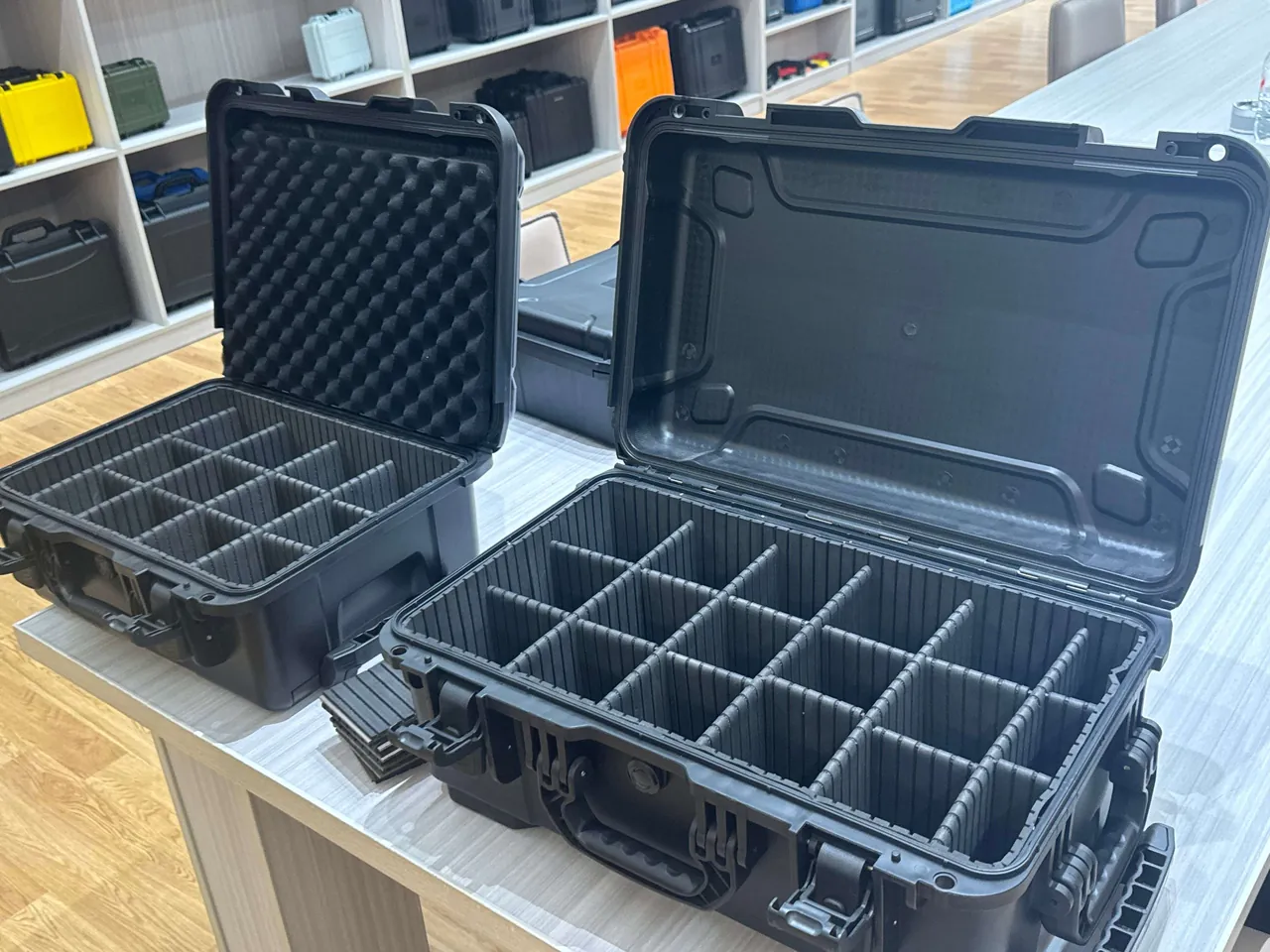
Layered isolation is the best value route. The build is: a 30 to 50 mm high-density PE load plate on the case floor, then a 15 to 25 mm high-damping elastomer layer, then the contoured insert, with the component seated in the insert. Weight is carried by the load plate, vibration is partly absorbed by the elastomer layer, and the component is simultaneously held softly. Note that the elastomer layer cannot be replaced with ordinary open-cell sponge, which compresses and deforms under sustained load so that restraint is lost late in the journey.
Suspended fixing suits very high-value components. Two contoured inserts sandwich the component from above and below, it touches no case wall, and all load passes through resilient supports. This demands precision at packing time because clamping force must be even; uneven force locally bruises the component. Mark compression witness lines on the insert so packing staff can see when the force is correct.
Whichever approach is used, run a seating check. After packing, apply gentle lateral force and confirm there is no perceptible movement; at unpacking, inspect for component bruising and insert collapse. This single step catches most insert design errors early.
Freeze and Moisture Control: Draining, Desiccant and Humidity Judgement
Freeze protection requirements for chiller parts cases exceed those for ordinary industrial cases, because these components carry water circuits by nature.
Draining should be a standardised, recorded operation. Steps: open the low-point drain valve, blow dry compressed air from the high point, confirm no water droplets at the low point, wait, then verify with a moisture check that no vapour remains at the ports, then fit plugs and apply a seal. The record should include time, ambient temperature and humidity, and the operator. For finned coil exchangers, keep blow pressure low so fins are not deformed.
Desiccant sizing differs from ordinary cases. Water circuits carry substantial residual vapour, so volume-based estimates can fall short. A working practice is to place desiccant separately in the exchanger cavity and in the pump cavity rather than once for the whole case, and to fix a humidity indicator card inside. A reading below 60 percent RH at unpacking is a pass. Where the journey exceeds three months or crosses hot, humid regions, use a reusable desiccant canister and print the replacement interval on the case exterior.
Sealing versus breathing is a trade-off. A fully sealed case develops a large internal-to-external pressure differential in air freight or high-altitude road transport, which makes opening difficult and deforms the gasket. Fit a case pressure equalisation valve for slow gas exchange without water ingress. Gasket material must be chosen for the transport temperature range; the discussion of low-temperature resilience in the comparison of case sealing materials is directly relevant, because a gasket that hardens in the cold loses its seal entirely.
For batches moving from cold to warm regions or the reverse, condensation driven by temperature differential also matters. Let component temperature equalise with ambient before closing the case, so residual heat in the compressor and coil does not pull condensation onto cold surfaces once the case is shut. The same low-differential packing discipline appears in cold chain and temperature-controlled cases.
Shell Structure Comparison
Shell structure selection follows unit weight, transport mode and the customer's cost sensitivity.
| Structure | Unit weight range | Main advantage | Watch out for |
|---|---|---|---|
| --- | --- | --- | --- |
| Injection moulded case (copolymer PP) | Up to 80 kg | Good sealing, consistent, wheel options | High tooling cost at large sizes |
| Rotomoulded case (HDPE) | 80 to 250 kg | Low-temperature impact, large sizes | Moderate wall thickness consistency |
| Aluminium frame composite | 50 to 200 kg | Rigid, serviceable, craneable | Seal depends on gasket, high cost |
| Steel frame timber crate | 200 to 800 kg | High load capacity, fumigable | Heavy, poor moisture resistance |
| Steel frame with composite panels | Above 500 kg | Craneable, insulation possible | Needs full corrosion protection |
For chiller components — heavy, vibration-sensitive, water-bearing — an injection moulded or rotomoulded case with a layered isolation insert is preferable to a steel-framed timber crate. A steel frame carries load well but is so rigid that it barely attenuates vibration, so the compressor's dynamic loads pass through unchanged. A plastic shell has useful elasticity and works with the insert as a second isolation stage.
Case dimensions must reserve thickness for the insert and the isolation layer. A working calculation is: internal clear dimension = largest component outline + insert thickness on both sides (usually 25 to 40 mm each) + isolation layer thickness (15 to 25 mm) + assembly allowance (10 to 20 mm). Many projects fill the internal volume at drawing stage and then discover at production that the isolation layer will not fit, forcing a downgrade in protection. This is avoidable.
Test Validation: Random Vibration, Stacking and Drop
Testing emphasis for chiller parts cases differs from general packaging. Random vibration carries more weight.
Random vibration is the core procedure. It reproduces the broadband random loading of road and rail transport and tests whether the insert holds components over time. After the test, check for component displacement, insert collapse or powdering, loosened fasteners and dislodged drain plugs. Its greatest value for a chiller case is exposing the difference between "designed with a gap" and "actually moves".
Stacking verifies compressive capacity during storage and consolidation. Chiller parts cases are heavy, and stacking height is often limited by what operators can handle, so the load is set from the actual stack height plus a safety factor. Apply the load to the load-bearing structure rather than the lid; if the lid itself is not structural, stacking data becomes meaningless.
Drop and concentrated impact apply to small cases shipped as single units. Above 100 kg, tip-over and concentrated impact usually replace free drop, because real handling produces forklift contact and tipping rather than free fall.
Choosing the basis. Export batches are best designed to ASTM D4169 distribution cycle testing; domestic batches follow GB/T 4857 for stacking and vibration; courier and LTL shipments can add the ISTA series. Test reports should include sample identification, conditions, duration and post-test inspection records. The full procedure set is described in the transport packaging test method overview.
Note that MIL-STD-810H vibration and shock methods are often cited as an environmental test method reference; they are applied here as method guidance only and do not indicate military certification.

Insert Tooling and Batch Consistency
Insert tooling determines whether protection performance reproduces consistently in volume production.
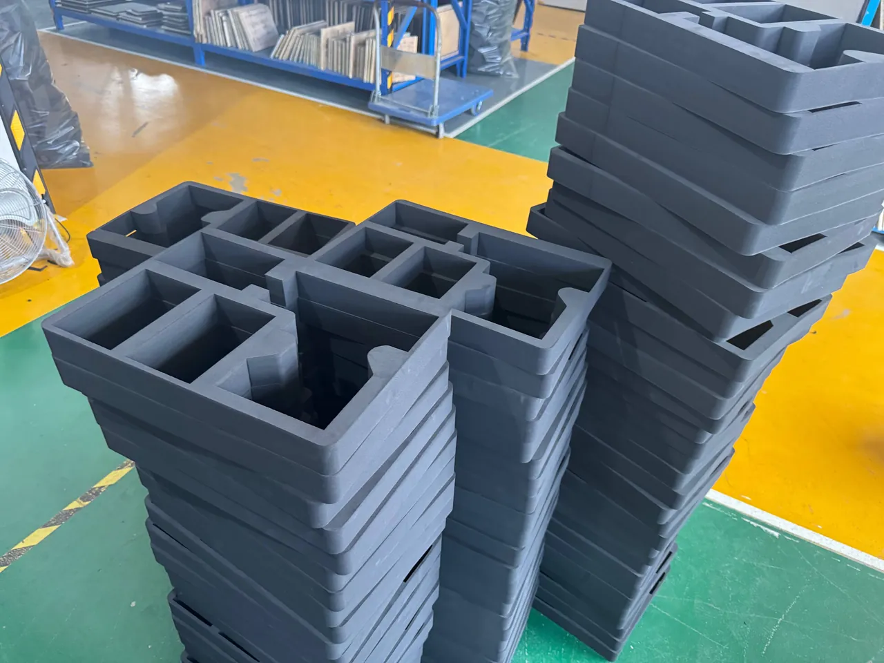
Three processes dominate. CNC routing suits sampling and low volume: high accuracy, fast revisions, but low throughput and visible tool marks. Die cutting suits medium and large volumes: low cost, high throughput, but limited for multi-layer composite structures, where complex contours require multiple cuts and manual assembly. Thermoforming suits curved geometries and high volume: excellent consistency, but requires tooling and expensive revisions.
One frequently overlooked point when choosing a process: multi-layer foam within one case, sourced from different batches, can have different compression and resilience, which directly changes how well components are restrained late in the journey. Fix the foam supplier and batch in series production and audit density and compression set at incoming inspection.
Foam density should be allocated by component weight. Base load layers typically use 45 to 70 kg/m³, locating layers 35 to 50 kg/m³, and top restraint pads 25 to 38 kg/m³. Too low a density gives insufficient support and collapse; too high a density removes cushioning benefit and can transmit shock straight into the component.
For cases opened and reused frequently, reinforce insert edges, since cavity lips wear first during loading and unloading. A common fix is to bond a wear-resistant fabric or thin leather strip along the cavity lip, which measurably extends insert life. Where a customer needs fast model switching, a modular arrangement of "common base insert plus model-specific locating layer" allows a change of locating layer alone to cover a different model; this is developed further in the guidance on custom EVA insert processes.
Frequently Asked Questions
Q: Can the chiller compressor and the condenser share one cavity?
A: The compressor is the heaviest item in the case, while the condenser contains many thin-walled tubes, so their tolerance to impact differs enormously. In a shared cavity, the small movements of the compressor under vibration press directly against the tube bundle or end covers of the condenser. That kind of squeezing rarely shows at unpacking; it surfaces later as leakage, and tracing it is expensive. Separate them by weight: give the compressor its own lower main cavity, put condensers and evaporators in an adjacent cavity, and carry load between them through a rigid divider. That divider must rest on ledges formed in the case side wall rather than on foam. If case dimensions genuinely prevent this, at minimum fit a rigid separation plate between the two and keep a clear gap of no less than 30 mm. Note also that the two cavities have different requirements: the compressor cavity needs oil film protection and damping pads, while the exchanger cavity needs draining, blow-drying and axial restraint. Combining them forces both configurations to compromise.
Q: How dry does a water circuit need to be before it passes?
A: The criterion is no visible water droplets after a settling period, and no condensed vapour at the ports. Practically: open the low-point drain valve and let it drain by gravity, then blow dry compressed air in from a high-point connection while watching misty vapour discharge at the low point until it stops. Stop blowing, wait 10 to 15 minutes, then hold a mirror or dry white paper at the port. No damp trace means pass. For finned coils, keep blow pressure below roughly 0.2 MPa so fins are not flattened. Fit plugs and apply a seal immediately after draining, and retain a record covering time, ambient conditions and operator. If the route's minimum temperature drops below freezing, add a low-temperature warning label on the plug. Treat draining as a traceable process rather than a one-off action: without a record nobody can establish responsibility if a tube splits from freezing in transit, and the process itself cannot be improved.
Q: How much desiccant does a chiller parts case need?
A: Volume alone is not a sufficient basis, because water circuits carry substantial residual vapour. Size desiccant per cavity: place separate quantities in the exchanger cavity and the pump cavity, at roughly 1.5 to 2.5 kg of silica gel per cubic metre of free cavity volume, taking the upper end for hot humid regions or sea voyages beyond two months. Fix a humidity indicator card inside; a reading below 60 percent RH at unpacking passes, while at or above requires desiccant replacement plus a corrosion re-check on metal parts. For components held in long-term stock, move to a reusable desiccant canister and print the replacement cycle on the case exterior so users do not let moisture protection lapse. Keep desiccant away from direct contact with stainless parts as well: some silica gel becomes mildly acidic once saturated, and prolonged contact can affect the stainless surface and become a later corrosion initiation point.
Q: Should chiller components use a contoured insert or a suspended insert?
A: It depends on component value and vibration sensitivity. A contoured insert seats the component in a formed cavity and restrains it through the cavity walls and floor. It is simpler and more cost-effective, and suits rigid items such as condensers and pumps. A suspended insert sandwiches the component between upper and lower inserts with no direct contact with the case wall, so all load passes through resilient supports. Attenuation is better and it suits large compressors and precision electronics. Be aware that suspended designs demand tight packing discipline because clamping force must be even, or the component is bruised locally. Mixed schemes are common in practice: suspended for the compressor, contoured for everything else, concentrating cost where it matters. Whichever is chosen, mark compression witness lines on the insert so packing staff can see when the force is correct, and inspect for bruising at unpacking. As a rule of thumb, allocate suspended inserts only to the two or three items where a bruise would trigger a rework, and keep contoured inserts everywhere else.
Q: Do case gaskets fail in low-temperature transport?
A: Yes, noticeably. Most rubbers harden and lose rebound speed at low temperature, so the gasket tracks irregularities in the case rim less well. If the journey crosses a significant temperature swing, the gasket may fail to seal against rim unevenness during the cold phase, creating a small path; when temperature recovers, the gasket closes again but the moisture that entered stays inside. For cold-region or cross-climate shipments, choose a sealing material with good low-temperature flexibility and verify compression resilience before packing. Also note that a fully sealed case generates a pressure differential as temperature changes, so fit a pressure equalisation valve for slow gas exchange without water ingress. Gaskets are wearing parts and belong in a scheduled replacement plan. Because failure is gradual rather than sudden, routine inspection and early replacement are cheaper than reactive handling, and they prevent components from sitting damp inside a case for weeks. Store spare gaskets flat in a dark place rather than coiled, since stored coils take a set that shows up as a leak path at the corners of the case rim.
Q: Can the factory packaging be removed from electronic expansion valves and filter driers in advance?
A: It should not be. The desiccant arrangement and sealing method inside factory packaging have been validated to keep the component dry through its shelf life. Once opened, molecular sieve begins adsorbing atmospheric moisture and its capacity declines; on an electronic expansion valve, water entering the narrow internal passages then freezing at low temperature blocks them outright. Keep factory packaging intact until the moment of installation. If a model check requires opening a box, do it quickly in a low-humidity environment, reseal immediately and add desiccant. Specify production date and shelf life in the purchase contract and control inventory turnover. Never store an unpacked component in open-cell foam packaging for long periods either: once the foam absorbs moisture it becomes a continuous vapour source rather than a barrier, and the original moisture protection design is defeated. If an inspection is unavoidable, use a vacuum-sealed bag with fresh desiccant for the return journey so the component is not left exposed.
Q: Is an acceleration recorder worth fitting?
A: For high-value batches, or where the customer has a defined vibration limit, yes. The cost of a recorder is negligible against the value of a compressor or a brazed plate exchanger, and it delivers two key pieces of information: the peak acceleration actually experienced in transit, and the time at which the peak occurred, which allows the specific leg to be traced. Reading the data at arrival tells you whether a targeted inspection is needed instead of guessing. On routes with a history of transport damage, recorder data also supports discussions with the carrier. Fix the recorder to the insert close to the protected component rather than to the case exterior, so the reading reflects the load the component actually saw. Where the customer has specified a vibration limit in the technical agreement, submit the recorder data as an acceptance attachment so acceptance rests on measured evidence. Choose a recorder with a sampling rate high enough to capture the dominant low-frequency peaks, otherwise the recorded maximum will understate what the compressor actually experienced.
Q: What should maintenance focus on for a reusable chiller parts case?
A: In descending order of impact: the vibration isolation layer, the gasket, the insert cavity lips, and the latches and hinges. The isolation layer gradually loses resilience under repeated compression, showing up as reduced component restraint, and typically needs assessment after three to five years. Gaskets harden under ultraviolet, ozone and oil exposure and are likewise scheduled wear items. Cavity lips wear with frequent loading and unloading, producing slight component movement that can be patched by bonding wear material locally. Inspect latches and hinges for cracks, particularly wheel axles and mounting bosses. Keep a usage log recording each route and unpacking result as the basis for maintenance decisions. For high-value components, re-confirm before every shipment that the isolation scheme still matches the current component weight and centre of gravity. A component redesigned since the last shipment may need a revised insert rather than a re-used one, and that check takes minutes against the cost of a damaged compressor.
Q: What test items are normally included when a customer asks for a test report?
A: The common set covers vibration, stacking and drop or concentrated impact, with the exact mix set by the distribution mode. For domestic sales and general export, GB/T 4857 stacking and vibration plus concentrated impact or drop satisfies most customers. For sea freight, multimodal transport or customers with a defined distribution cycle, ASTM D4169 with the corresponding level is more persuasive. Courier and LTL batches can add ISTA 3A or 3E. If a customer mentions a military standard, clarify in advance that MIL-STD-810H applies here only as an environmental test method reference and does not indicate military certification. All reports should come from an appropriately accredited third-party laboratory and include a post-test unpacking inspection record. For chiller components specifically, report the condition of the water circuit plugs and the insert state after vibration testing separately, since those two items best reflect long-term reliability. Where a customer operates in a cold climate, an additional low-temperature conditioning step before the vibration test gives a much more realistic picture of gasket and foam behaviour.
Conclusion and Further Reading
Chiller parts case design reduces to three threads. Vibration first: seat the compressor on a structural load path, attenuate low-frequency motion with layered isolation rather than thicker foam, and restrain displacement with blocks. Water second: run exchangers and pumps through drain, blow-dry and plug, back it with per-cavity desiccant and a humidity indicator card, and eliminate both freeze cracking and corrosion. Cleanliness and static third: keep metering components and filters in factory packaging, bag electronics in shielding material, suspend them rather than clamp them, and cap every terminal. Only once those three threads are in place do shell structure, sealing grade and test validation deliver real value.
JUNZHJIA builds refrigeration and heat-transfer equipment parts cases around layered isolation inserts and per-cavity moisture control, and can supply model-specific custom inserts, OEM/ODM production and supporting inspection documents, with seals and damping materials matched to the machine model. Where a customer limit must be confirmed at design stage, run a vibration screening test during sampling so that problems are solved on the drawing and on the first article rather than in the field.
Further Reading