

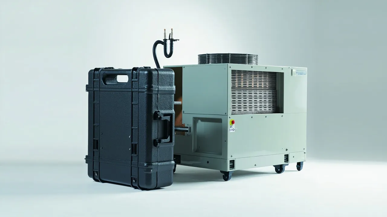
An air handling unit parts case deals with an unusual object: not a complete machine and not loose components, but a functional unit shipped in sections. Coil sections, fan sections, filter sections and humidifier sections are assembled into the whole on site, and every section carries flanges, sealing faces and insulation. For sectional shipments, the real risk is not impact damage but a compromised interface — a section that leaks air or water, or fails a cleanliness requirement, after assembly on site. Case design therefore centres on protecting interfaces, coils and filter sealing faces, while managing every accessory needed for site assembly by unit.
In cleanroom, pharmaceutical and electronics projects, AHU airtightness directly affects cleanliness classification and energy consumption. If a coil's fins are extensively flattened, heat transfer falls and the unit compensates with higher airflow or lower supply temperature, raising energy use. If a filter section sealing face is nicked in transit, even a correctly installed HEPA filter bypasses and leaks, and the cleanliness class fails outright. None of this is visible on the day the case is opened; it surfaces during commissioning and acceptance. This guide follows three threads — sections, interfaces and cleanliness — and sets out protection and acceptance measures for AHU cases.
Table of Contents
- Why Air Handling Units Ship in Sections
- Matching the Section Plan to the Case Breakdown
- Coil Sections: Fins and Headers Need Different Protection
- Water Circuit Treatment and Connection Protection for Coils
- Fan Sections: Impeller, Bearings and Isolators
- Filter Sections and Cleanliness: The HEPA Sealing Face
- Humidifier Sections and Cooling Coils: Stainless Parts and Residual Water
- Casing Panels and Profiles: Preserving Insulation and Gaskets
- Dampers, Actuators and Sensors
- Protecting Field Assembly Interfaces
- Inserts and Supports: A Common Platform for Sectional Cases
- Testing and Acceptance: Airtightness and Cleanliness Checks
- Delivery Documentation and Case Marking
- Frequently Asked Questions
- Conclusion and Further Reading
Why Air Handling Units Ship in Sections
Air handling units are rarely shipped whole, for three reasons that all bear directly on case design.
The first is size. A modular AHU can run to more than ten metres in length with six to ten functional sections. The assembled unit is far outside normal transport limits, while individual sections stay within manageable dimensions and can use standard cases or pallets.
The second is site access. Cleanroom mechanical rooms usually have a defined rigging opening and access route, and a complete unit will not fit through. Sections must be brought in and assembled inside the plant room, so section dimensions must match the clear dimensions of the opening and route. Confirm this with the customer before case design starts.
The third is functional diversity. Coil sections are heavy, filter sections demand high cleanliness, humidifier sections contain stainless parts, and fan sections contain rotating machinery. Sectioning allows a dedicated protection scheme for each rather than one generic package stretched across all of them.
Sectioning introduces a new risk: exposed interfaces. In an assembled unit, flange pairs are clamped by bolts and the gasket sits compressed. Once sectioned, flange faces are bare and the gasket is either stored with the section or removed and packed separately. Any impact in transit lands on these bare faces, and when sections are joined on site, flange flatness and gasket integrity determine airtightness.
The design order for an AHU case is therefore: fix the section plan and rigging sequence first, then design the case and insert. That is the reverse of the order used for a complete-machine case.
Matching the Section Plan to the Case Breakdown
The section plan is agreed between the unit manufacturer and the customer, and the case breakdown must map to it one to one.
| Functional section | Main components | Protection priority | Case recommendation |
|---|---|---|---|
| --- | --- | --- | --- |
| Mixing section | Dampers, filter rails | Vane locking, rail flatness | Mid-size case, may combine with light sections |
| Filter section | Filter frame, sealing face | Sealing face flatness, frame rigidity | Dedicated case, clean packaging |
| Coil section | Cooling and heating coils | Fins, headers, connections | Dedicated case, base-mounted load path |
| Fan section | Centrifugal fan, motor, isolators | Impeller shape retention, isolator unloading | Dedicated case, rigid load path |
| Humidifier section | Spray pipes, eliminators, stainless parts | Stainless cleanliness, residual water | Dedicated case, drained and blow-dried |
| Silencer section | Splitter baffles, perforated plate | Baffle deformation, absorbent moisture | Dedicated case, moisture protection |
Combining sections in one case reduces cost and volume, but only under strict conditions: only light sections without cleanliness requirements may be combined, interface faces must face inward with dedicated protection, and accessories must be stored in separate compartments. Filter sections and humidifier sections should not be combined with others — the first for cleanliness, the second because it carries water.
Each case label should carry the unit number, section number, section type, position in the unit sequence, weight, lifting point locations and installation orientation. A common on-site assembly error is installing a section backwards, leaving connections or access doors facing the wrong way. Printing "section number of total" on the label is the simplest error-proofing measure.
An assembly sequence drawing should travel with the case as well, showing the joining order and the bolt specification for each joint. Its value often exceeds the cost of the case itself, because delays in site assembly cost far more than packaging material.
Coil Sections: Fins and Headers Need Different Protection
Coils — cooling and heating — are among the most valuable components in an AHU and carry the densest fin pack.
Fin protection follows the same logic as a plate-fin cooler, but with tighter requirements because AHU coil fins are thinner (0.1 to 0.2 mm aluminium foil) with closer spacing (1.5 to 2.5 mm). Any lateral rubbing flattens fins over a large area, and flattened fins not only lose heat transfer area but also raise air-side pressure drop, which shows up directly in fan energy.
Three layers apply. First, the fin face must point toward a non-rubbing direction inside the case, usually upward or toward the case centre. Second, fit protective rails around the coil so possible point contact becomes line contact. Third, fit a removable protective mesh or rigid guard over the fin face with a 5 to 10 mm gap, so the guard itself never presses on the fins under vibration.
Headers and connections matter just as much. Coil headers, usually copper or steel tube welded to the coil end plates, have inlet and outlet connections projecting beyond the casing. An impact in transit bends a connection and applies a bending moment to the welded joint at the end plate, which can crack the weld or distort the header. Fit rigid supports that tie the connections back to the insert or case structure so impact force travels through the support rather than the weld. Cap every connection port with a plug plus dust cap.
| Protected item | Failure mode | Consequence | Protection measure |
|---|---|---|---|
| --- | --- | --- | --- |
| Fins | Lateral rubbing, bending | Reduced area, higher pressure drop | Fins up, edge rails, removable guard |
| Headers | Bending under impact | Weld cracking, uneven flow distribution | Independent support, plug, dust cap |
| End plates | Crushing | Distortion of the whole coil | Support at end plate locations, avoid mid-span load |
| Connections | Kinking, flattening | Changed flow characteristics | Rigid support tied to case structure |
| Condensate tray | Distortion, coating damage | Poor drainage, corrosion | Dedicated support pad, coating protection |
The table shows why "wrap it up" is not sufficient for a coil section: every load-bearing feature needs its own load path.
Water Circuit Treatment and Connection Protection for Coils
The coil is the only AHU component that simultaneously involves water, copper, aluminium and steel, and poor water circuit treatment triggers both freeze damage and galvanic corrosion.
Draining and blow-drying is mandatory. Coil water volumes are substantial and the multi-circuit parallel construction makes low points hard to clear. Export or winter shipments must follow drain, blow-dry and plug, with a moisture check confirming no vapour at the ports. If the route crosses a cold region, residual water freezes, expands and splits copper tubes — damage that is invisible at unpacking and only appears during pressure testing.
Nitrogen blanketing is an optional enhancement. For high-value coils or long sea voyages, charge a slight positive nitrogen pressure after draining and plug the ports. This prevents internal oxidation and, if a pressure gauge is fitted, gives an immediate indication of whether leakage occurred in transit. The practice is common in the refrigeration industry, costs little and helps quality control.
Galvanic corrosion needs attention. Aluminium fins and copper tubes differ in potential, so in a damp environment with condensate present they form a corrosion cell. Coils normally receive a fin coating — hydrophilic or anti-corrosion — and any coating damage in transit becomes a corrosion initiation point. Friction between insert and fins must therefore be tightly controlled, and internal case humidity kept below 60 percent RH.
Condensate trays are frequently overlooked. They are thin stainless or galvanised fabrications, complex in shape, and they distort under compression, changing the drainage slope and allowing water to pool. Support the tray from below through a dedicated pad; never strap across the tray edge. If tray and coil ship as one assembly, confirm the tray's load path is not obstructed by the coil.
For general requirements shared with comparable heat transfer components, see heat exchanger parts cases. Where coil sections ship together with cooling source equipment, the vibration and water circuit practice in industrial chiller parts cases applies directly.
Fan Sections: Impeller, Bearings and Isolators
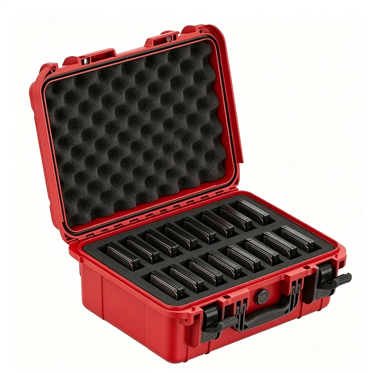
Fan section protection resembles centrifugal blower cases, with added complexity from shipping as a complete section.
Impellers need shape-retaining restraint. AHUs typically use double-inlet centrifugal or backward-curved fans with wide impellers supported at both bearings. Deformation concentrates at blade outlet edges and shroud rims, so use a curved cradle supporting the hub or shaft with blades fully suspended on all sides. Where the impeller is wide, provide one support at each bearing position so a single support point cannot bend the shaft.
Bearings and housings are governed by coaxiality. When the fan casing and motor base ship as one assembly, housing position is guaranteed by casing rigidity. When they ship separately, add transport location inside the case. A transport dowel or support block between motor and fan prevents motor weight and inertia from loading the bearings through the coupling.
Isolators are the fan section's specific problem. AHU fans normally sit on spring or rubber isolators inside the casing. Without unloading during transport, the isolators carry load continuously, springs can take a plastic set and rubber elements take a permanent compression. Fit transport support blocks between the fan base frame and the casing so the fan weight goes straight into the casing structure; remove the blocks on site and the isolators resume working. Blocks must be conspicuous and labelled "remove before installation".
Fan inlet and outlet flanges are interfaces and need protective covers against distortion and contamination. Where a fan section ships complete, the flange faces are critical to the site joint, so record flatness at the factory and re-measure on arrival.
Motors deserve separate thought. Long storage can redistribute bearing grease, so where the transit period is long, bar the motor over by hand on arrival as the manufacturer requires. Seal the terminal box cover, cap the terminals and protect them from moisture and impact.
Filter Sections and Cleanliness: The HEPA Sealing Face
The filter section carries the highest cleanliness requirement in an AHU case, and what it protects is not mass but precision surfaces.
HEPA and ULPA sealing faces are central. Filters seal to their frames by gasket or gel seal to eliminate bypass, and a sealing face damaged or contaminated in transit will leak even when correctly installed. Filter sections therefore normally ship without filters installed — frames only, with filters packed separately for site installation. If a customer requires filters to travel with the section, keep factory packaging intact and protect against compression inside the case.
Filter frame flatness is the acceptance focus. Frames are aluminium or galvanised steel with moderate rigidity, and crushing distorts flatness, directly degrading sealing. Support frames at their edges rather than mid-span; when stacking several frames, place rigid dividers between layers and limit the stack count according to frame stiffness.
Cleanliness control runs through the whole packing process. Following the ISO 14644 classification approach, filter sections and their frames must be protected from dust, fibre and oil from the packing stage onward. Practical requirements: use non-shedding packaging materials and avoid ordinary cardboard and open-cell foam; work in as clean an environment as practical; add clean bags and desiccant inside the case. For customers serving ISO Class 5 or cleaner areas, align the packaging scheme with their cleanroom management procedures.
Case marking for filter sections should state "clean item", "do not open in advance" and "keep sealed until installation". If a case is opened in a non-clean environment on site, the component becomes a particle source for the cleanroom even if it is physically intact.
Humidifier Sections and Cooling Coils: Stainless Parts and Residual Water
The humidifier section operates in the harshest environment of any AHU section, and its transport protection is the most frequently simplified.
Spray humidifier sections contain spray pipes, nozzles, eliminators and a water tank. Nozzles are precision items whose performance collapses once orifices are blocked or deformed. Eliminators are folded thin-sheet parts that distort easily. Tanks are often stainless with weld and polish requirements. Transport protection should: remove and pack nozzles separately or cap them; fix eliminator plates individually to prevent inter-plate rubbing; drain and blow-dry the tank and plug it, so residual water can neither freeze in cold conditions nor support microbial growth in warm humid ones.
Steam humidifier sections contain steam distribution pipes and steam traps. Distribution pipes are long and cantilever-mounted, so inertia bends them in transit. Fit a mid-span or end support to convert the cantilever into a simply supported beam.
Evaporative (wet media) humidifier sections use organic or inorganic fibre media that lose strength when wet and support mould growth. Keep media dry and in factory packaging, and add desiccant to the case.
Stainless part contamination is specific to humidifier sections. When stainless contacts carbon steel in a damp environment, the galvanic couple produces rust marks on the stainless, and in food, pharmaceutical and electronics projects those marks are unacceptable. Pack stainless separately from carbon steel with isolating pads at contact points, and avoid chlorine-containing materials inside the case, such as certain PVC foams, because chloride ions break down the passive layer.
Distinguishing cooling coils from heating coils matters. Cooling coils operate wet and carry condensate; heating coils are normally dry. Although structurally similar, water circuit requirements differ: cooling coils emphasise draining and corrosion protection, heating coils emphasise fin protection and connection support. When both sit in one section, zone them inside the case and label them separately.
Casing Panels and Profiles: Preserving Insulation and Gaskets
The casing panels and profiles are themselves components requiring protection, since they determine the unit's airtightness and insulation performance.
Panels are usually double-skin steel with polyurethane or mineral wool insulation. In transit, the risk is edge impact that distorts the panel and opens an oversized gap at the joint, plus coating scratches that become corrosion sites. Panels should be stacked vertically or flat with interleaves, and the stack height limited by the compression performance of the insulation. On foamed panels, edges are the weak points and need edge protection.
Profiles — aluminium or steel frame sections — have end faces and slots that are mating surfaces. End face damage affects joint accuracy and slot distortion affects gasket installation. Fix profiles along their length so no unsupported span can bend under vibration.
Gaskets are the key to airtightness and the component most likely to fail in transit. Made of EPDM, silicone or PVC, they take a compression set when loaded for long periods. A gasket shipped compressed with a panel may not rebound to the required sealing height on arrival. Pack gaskets separately in their natural state, labelled with material and application. If schedule pressure forces pre-installation, loosen the joint faces before packing so the gasket is not compressed for the whole journey.
Insulation must be kept dry. Mineral wool loses insulating performance once damp and can support microbial growth; polyurethane can also absorb moisture over long humid exposure. Add desiccant inside the case and mark it "keep dry", and avoid open-yard storage at the port.
Access doors and inspection windows open or distort easily in transit. Lock door hinges and latches for transport, and apply protective film to glass or acrylic windows to prevent scratching.
| Component | Storage condition | Main reason |
|---|---|---|
| --- | --- | --- |
| Gaskets | Natural state, dark, no long compression | Prevent compression set |
| Insulated panels | Dry, no stacking load | Prevent moisture uptake and compression |
| HEPA filters | Factory sealed, dry, no compression | Protect sealing face and media |
| Eliminator plates | Individually fixed, no rubbing | Prevent bending and coating damage |
| Stainless parts | Isolated from carbon steel, chloride-free | Prevent galvanic corrosion and passive layer damage |
| Nozzles and sensors | Individually packed with caps | Prevent orifice blockage and probe deformation |
Dampers, Actuators and Sensors
AHU sections contain many dampers, actuators and sensors. Unit prices are low, but on-site replacement is troublesome.
Dampers — outdoor air, return air, exhaust air and mixing — have blades that swing freely under transport vibration, causing fretting between shaft and bushing and eventually poor closure. Lock them for transport with retaining clips, locating pins or low-tack tape holding the blade closed or at mid position. For export batches, use mechanical locks and mark the removal requirement both inside and outside the case.
Electric and pneumatic actuators should be removed and packed separately. Their weight and inertia apply a bending moment to the damper shaft, especially on high-torque units. Cap the shaft end after removal and record the actuator's mounting position and orientation so it cannot be installed reversed.
Sensors — temperature, humidity, differential pressure and air velocity — have high-precision, fragile probes and should stay in factory packaging. Differential pressure sensing tubes are thin and soft; coil them separately and never let them kink.
Wiring and terminals need disciplined management. Photograph the wiring before disconnecting; cap every terminal afterwards; bundle multicore harnesses with ties and label each circuit. Wiring errors are among the most common causes of commissioning delay, and proper terminal labelling cuts troubleshooting time dramatically.
Protecting Field Assembly Interfaces
For a sectional AHU, interfaces determine success or failure. Every interface protection measure follows one rule: the protected face must never become a load-bearing face.
Flange interfaces join section to section. Fit protective covers bolted to the flange, which resists distortion and excludes dust. Where a flange face has a flatness requirement, record the data at the factory, supply it with the case, and re-measure on arrival.
Sealing faces include inter-section seals, filter frame seals and access door seals. These faces tolerate no impact or contamination. Apply protective film or covers and keep internal humidity low. If gaskets are pre-installed on sealing faces, they must be in an uncompressed state.
Bolts and fasteners should be grouped by section and by specification, with the application labelled on each package. Supply a bolt list covering specification, quantity and torque requirement. Mixing specifications is the most common low-level error on site and wastes substantial time in part hunting.
Location pins and guides matter especially on large units. Where sections are located by dowels, supply them with the case in a corrosion-protected condition. If dowels are already fitted to the flange at the factory, protect them with covers.
Connection tie-ins need reserved access. Coil connections, humidifier pipes and condensate drains are all broken at the section boundary and must be reconnected on site. Protect the ports with plugs and dust caps, and pack the matching fittings, valves and gaskets grouped by system with labels. Where welding is used, chamfer the port and apply corrosion protection.
Cables and signal wiring between sections also need reserved access. If cables are disconnected before shipping, label them thoroughly. If they remain connected and travel with the sections, add protective sleeving to prevent abrasion.
Inserts and Supports: A Common Platform for Sectional Cases
AHU projects involve many section types in small batch quantities, so a common platform for cases and inserts cuts cost and lead time significantly.
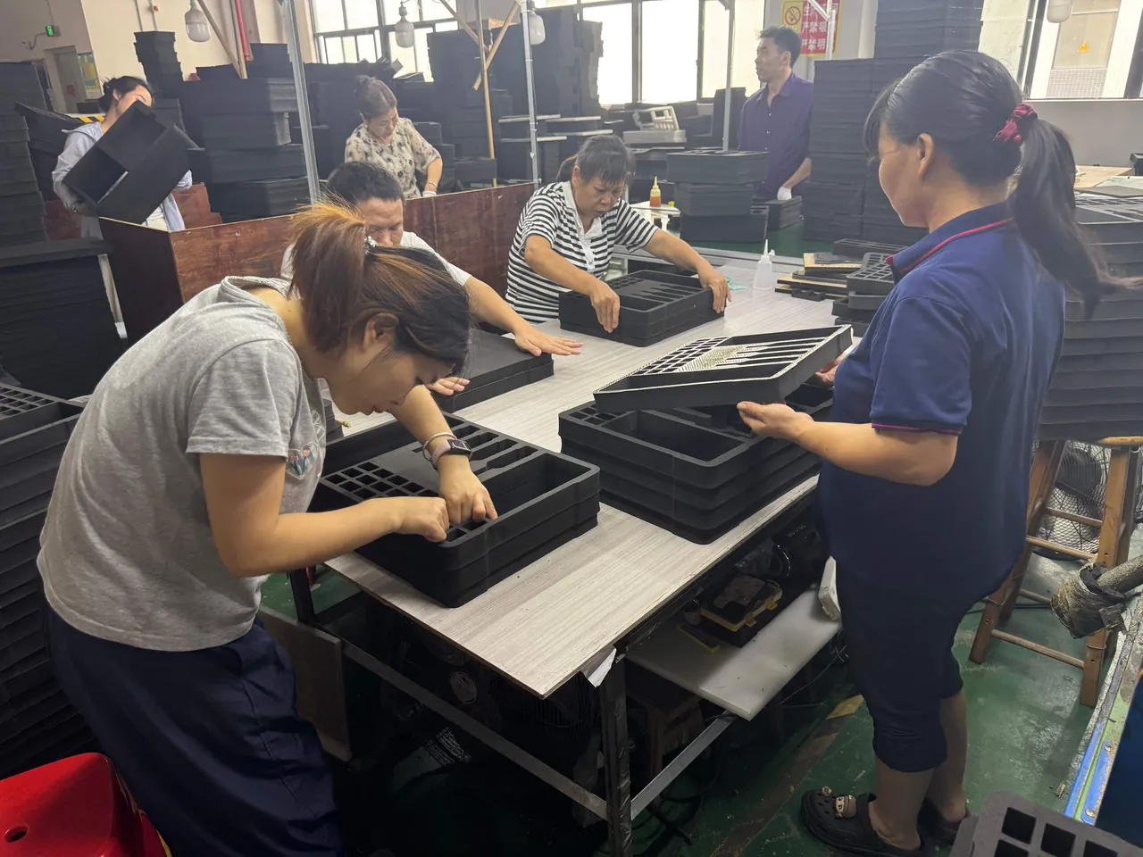
The concept is "standard case size series with modular inserts by section type". Cases are divided into length and width series covering most coil and fan sections, while inserts are made as interchangeable modules per section type, allowing one case size to serve different sections by changing the insert. Tooling and fixtures are reused, and a new section type needs only a new insert module.
Load paths in inserts must distinguish heavy from light sections. Coil and fan sections are heavy and need generous bearing area plus rigid support. Filter and silencer sections are light, where the insert's task is retention and cleanliness protection rather than load bearing. Where both categories share a case type, differentiated insert construction is essential.
Removable dividers are very useful in sectional cases. They allow several independent cavities inside one case, separating sections or accessories and simplifying staged retrieval on site. Dividers must lock reliably so they cannot work loose in transit and become an impact source. Comparable structure is described in the guidance on case removable divider systems.
Support placement must avoid interfaces. All load-bearing supports belong at panels, profiles and end plates — rigid features — while interface flanges and sealing faces stay suspended. Where space forces a support close to a flange, use compliant material and enlarge the contact area so pressure drops to an acceptable level.
Cases for clean sections benefit from double protection: an insert for mechanical protection plus a clean bag for contamination isolation. Clean bag film should be low-outgassing and non-shedding, and the closure method should allow opening inside a clean environment. Where a customer specifies a cleanliness class, align the packaging scheme with their cleanroom procedures and keep records.
For materials, inserts contacting clean items should be non-shedding with a dense surface. The reasoning behind material surface characteristics and dusting tendency is covered in the custom foam insert guide.
Testing and Acceptance: Airtightness and Cleanliness Checks
AHU case testing falls into two groups: packaging transport tests and interface protection checks.
| Check item | Method | Acceptance focus |
|---|---|---|
| --- | --- | --- |
| Static stacking | Load to actual stack count for 24 hours | No section distortion, no change in interface flatness |
| Random vibration | Simulate road and rail transport | No displacement, no insert collapse, no interface contact damage |
| Concentrated impact | Simulate forklift contact and tipping | No panel dents, no profile distortion |
| Interface re-measurement | Measure at factory and on arrival | Flatness delta within allowance |
| Cleanliness check | Visual and wipe inspection | No oil, no fibre, no metal swarf |
| Water circuit recheck | Visual and moisture detection | No droplets, no vapour at ports |
Interface re-measurement is the key item. Measure each section flange flatness before dispatch using a straight edge with feeler gauges, or a surface plate with a dial indicator, and supply the data with the case. Re-measure the same way on arrival; the delta is the transport effect. This converts "is it damaged" from a subjective judgement into a data comparison, which is valuable for both acceptance and liability allocation.
Cleanliness checks should happen immediately after unpacking, because once the item enters the site environment, contamination sources become untraceable. At minimum, check for metal swarf and foreign objects on fins, fibre on filter frames, rust marks on stainless parts, and oil anywhere in the case. For high-class cleanroom customers, follow their procedure for surface wipe sampling after opening.
On test basis, domestic batches follow GB/T 4857 for stacking and vibration; export and multimodal batches are best defined by ASTM D4169 distribution cycles; courier and LTL shipments can add the ISTA series. The full procedure set is in the transport packaging test method overview. Note that MIL-STD-810H is applied here only as an environmental test method reference and does not indicate military certification.
Sampling. Heavy and critical sections — coil and fan — should be inspected 100 percent. Light repeated items such as multiple identical filter frames can be sampled at AQL general inspection level II. The rules are covered in custom case acceptance and AQL sampling.
Delivery Documentation and Case Marking
Delivery documentation for a sectional AHU case carries substantial value, because it directly affects site assembly efficiency.
Recommended document set: section list and section number cross-reference, assembly sequence drawing, bolt list with specifications and torque, gasket and shim list, interface flatness records, hydrostatic or nitrogen blanketing records where applicable, clean item list with opening requirements, pre-reassembly checklist, and lifting point diagram.
Case marking should carry: unit number, section number and total, section type, weight, dimensions, lifting points, centre of gravity where relevant, orientation marks, stacking limits, cleanliness marking where applicable, and "remove transport supports before installation" where applicable. On large sections, mark the section number on all four sides so it remains visible during rigging.
Marking durability matters especially on construction sites, where rain, mud and abrasion destroy ordinary labels quickly. Use laminated labels or metal tags, and avoid placing them on corners that wear.
Transport support marking must be conspicuous. Fan section support blocks, coil connection supports and valve locking devices are all "must remove" items. Colour them orange or bright yellow, add warning labels, and list the removal steps in the assembly sequence drawing so they cannot be overlooked.
Frequently Asked Questions
Q: When should the AHU section plan be fixed?
A: Before packaging design begins, not after. Section dimensions are constrained by the plant room rigging opening and access route, so those site conditions must be confirmed first, and then section length, width and weight decided. Once the section plan is fixed, case size, insert construction, lifting points and transport mode all follow from it. Reversing the order commonly ends with a case that cannot pass the rigging opening, forcing on-site unpacking and repacking, which is uneconomical and a quality risk. The section plan should also confirm with the manufacturer which sections may be joined on site and which must arrive complete, because some sections, such as fully foamed insulated ones, are unsuitable for secondary work on site. Where a project is delivered in phases, agree the section numbering convention across all phases so identical numbers cannot refer to different sections on site. Also verify that the chosen section split does not place a joint where a coil connection or damper actuator is mounted, since those are far easier to handle with the section intact than after separation.
Q: How far does coil fin protection need to go?
A: The target is zero lateral rubbing. Fin spacing is typically only 1.5 to 2.5 mm and foil thickness 0.1 to 0.2 mm, so any sustained lateral rubbing flattens fins over a wide area. In practice, orient the fin face upward or toward the case centre, fit edge rails to convert point contact into line contact, and add a removable guard over the fin face with a 5 to 10 mm gap. The acceptance criterion is not merely whether any fin is bent but the proportion of area affected and its location: a small amount of edge flattening usually has negligible thermal effect, while a broad patch in the middle of the coil clearly raises pressure drop. Assess visually by zone on arrival and photograph for the record. Where a customer is energy sensitive, measure flattening depth at sample points with a fin comb and convert a subjective judgement into comparable data. Record the reading positions on a simple sketch so the same points can be checked again after any future shipment and compared directly.
Q: Do fan section isolators need unloading during transport?
A: Yes. AHU fans are usually mounted inside the casing on spring or rubber isolators, and without unloading the isolators carry fan weight and vibration throughout the journey. Springs may take a plastic set, and rubber elements take a permanent compression and stiffen in the cold; either changes the fan's natural frequency and the effectiveness of isolation. Fit transport support blocks between the fan base frame and the casing so weight travels directly into the casing structure, then remove the blocks on site so the isolators resume working. Blocks must be conspicuously coloured and labelled, and the removal step must appear in the assembly sequence drawing. Where a section is transferred several times, keep the blocks with the case so nobody improvises a substitute from loose timber, which introduces an uncontrolled load path. Label the blocks with the section number as well, since a set left loose in a plant room is easily fitted to the wrong unit and then removed at the wrong time.
Q: Should HEPA filters ship with the section or separately?
A: Separately, with installation on site, is preferable. The sealing face between filter and frame demands high precision, and shipping inside a section exposes it to compression and contamination. Once a sealing face is damaged or the media has absorbed moisture, the filter cannot reach its rated efficiency even if it looks intact. If a customer insists on shipping filters with the section, keep factory packaging intact, protect against compression inside the case, and mark the case as a clean item that must not be opened in advance. Keep the transport and storage environment dry with desiccant inside the case. On arrival, complete the external inspection before the item enters the clean area, confirm the packaging is intact, then open and install at the designated location. Confirm the airflow arrow direction immediately after opening, since media has a defined orientation and fitting it reversed raises pressure drop and shortens service life. If the filter must wait before installation, return it to its packaging and reseal it rather than leaving it standing open in the plant room.
Q: Why can stainless parts not be packed with carbon steel?
A: Because of galvanic corrosion. Where stainless and carbon steel touch in a damp environment, the potential difference forms a corrosion cell; the carbon steel is attacked as the anode, and the stainless may show rust marks or passive layer breakdown. In food, pharmaceutical and electronics projects, rust marks on stainless are an unacceptable defect. Pack stainless separately from carbon steel with isolating pads at contact points, and avoid chlorine-containing materials inside the case, because chloride ions destroy the stainless passive layer. Stainless parts should also avoid sharing a cavity with components that generate metal swarf, since adhering iron particles become later corrosion initiation sites. If machined stainless surfaces carry free iron residue, passivate or pickle them before packing, otherwise they will rust in a damp environment just like carbon steel. Choose packing materials with no chloride content, and confirm this with the supplier in writing rather than assuming it from the material name.
Q: Should gaskets be pre-installed or packed separately?
A: Packed separately, except where schedule pressure makes it unavoidable. Gaskets are elastomers, and long-term compression produces compression set, so they cannot rebound to the designed sealing height on arrival and unit airtightness fails. Store them separately in their natural state, protected from light, labelled with material and application. If pre-installation is unavoidable, loosen the joint faces before packing so the gasket is not compressed, and keep the transit period as short as possible. Whichever route is chosen, gasket material must match the design duty; for example, cold duty calls for a compound with better low-temperature flexibility. Keep gaskets away from oils and solvents before installation as well, since contact causes swelling and destroys dimensional stability. Store them flat rather than coiled, and where a joint uses several gasket lengths, bag them together with the joint number so a mix-up at assembly is impossible. Order spares at the same time as the unit rather than after the first leak appears, because a matched gasket is quick to fit while a substitute cut on site rarely achieves the same sealing performance.
Q: Should interface flatness be recorded at the factory?
A: Strongly recommended. For a sectional shipment, interfaces are the critical joint on site, and without a factory baseline, deciding whether transport caused damage becomes a matter of opinion. Measure each section flange flatness before dispatch using a straight edge with feeler gauges, or a plate with a dial indicator, supply the data with the case, and re-measure the same way on arrival. The delta is the transport effect. This delivers three benefits: objective acceptance criteria, a defensible basis for allocating responsibility, and useful feedback for improving insert and support design. For cleanliness projects with high airtightness requirements, the return on this record is significant. Where the customer employs a supervisor, invite them to witness and sign the factory measurements to reduce later disputes. Photograph each flange with the measuring instrument in place, so the record shows not only the number but also how it was obtained and at which point on the face.
Q: What special requirements apply to packaging materials for clean sections?
A: The core requirements are non-shedding, low-outgassing and non-hygroscopic. Ordinary corrugated board produces paper dust and fibre, and open-cell foam sheds particles and absorbs moisture; neither should contact clean items directly. Use dense, low-outgassing films and closed-cell foam, and add a clean bag as a secondary barrier outside the insert. Do the packing in as clean an environment as practical, and never seal a case in a dusty area. For customers serving areas classified under ISO 14644 at higher cleanliness levels, align the packaging scheme with their cleanroom procedures, defining the opening location, opening method and record requirements. Avoid chlorine-containing materials inside the case so stainless parts are protected over the long term. Where items are stored for months, sample the particle count inside the clean bag periodically. Note also that the clean bag should be opened only once, immediately before installation, since repeated opening and resealing defeats its purpose and recontaminates the item each time.
Q: Does a common case platform reduce protection effectiveness?
A: Not if it is done properly. The key is a common case with a dedicated insert: cases are divided into size series covering most section types, while inserts are interchangeable modules per section type, with high-load structures for heavy sections and retention plus cleanliness protection for light ones. Protection for each section is still designed to its own requirements; only the case and tooling are commonised. Note that the stacking limit for a common case must be set by the heaviest section it may carry and stated on the label. Where one case type serves sections with very different weights, the label must carry the corresponding figures so nobody on site stacks a light-section case as though it were a heavy one. Whenever an insert is changed, re-verify that the lifting points still align with the section centre of gravity. It is also sensible to photograph the loaded case before closing the lid, because a clear record of how the section was packed shortens every later discussion about displacement or missing accessories.
Conclusion and Further Reading
AHU case design comes down to three statements. Fix the sections first, then the case: section dimensions are constrained by the rigging opening and access route, and case size, insert construction and lifting points all follow the section plan. Protect interfaces above appearance: flange flatness, sealing face cleanliness and gasket resilience decide post-assembly airtightness, and they outrank panel cosmetics. Control cleanliness and dryness together: filter and humidifier sections carry the highest cleanliness requirements, so packaging materials must be non-shedding and non-hygroscopic, internal humidity must stay low, and stainless parts must be strictly isolated from carbon steel.
At the delivery level, the assembly sequence drawing, bolt list, interface flatness record and pre-reassembly checklist supplied with the case are often worth as much as the case itself, because they determine how fast and how well the site assembly goes. JUNZHJIA builds air handling and purification equipment cases on a common case platform with modular inserts, supplying section-specific inserts, clean packaging and supporting documentation, with OEM/ODM programmes, section cases managed by unit number, and corresponding inspection records.
Further Reading