

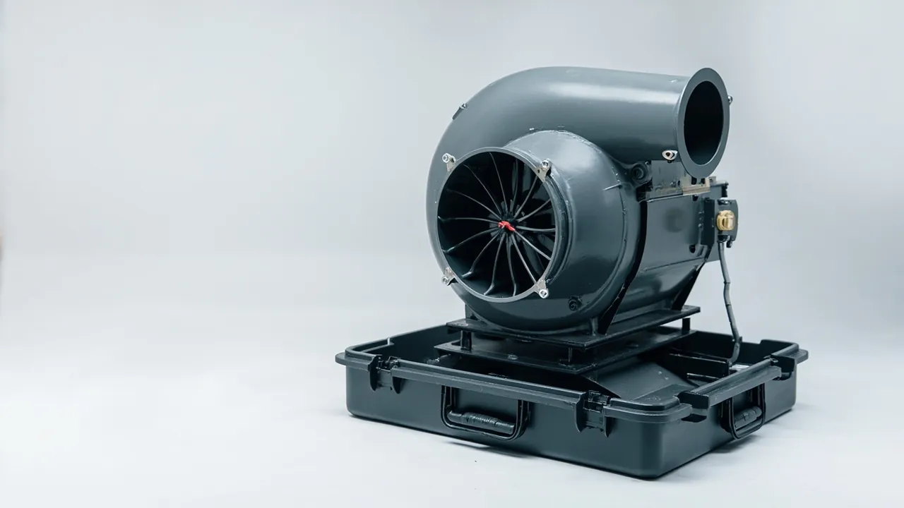
A centrifugal blower parts case has one job: deliver the impeller, casing, inlet cone and shaft without deformation beyond tolerance. A fan's performance curve is set by its geometry — a few tenths of a millimetre change in impeller diameter, or one millimetre of added radial clearance between the inlet cone and the impeller, can move airflow and static pressure measurably off the design point. Worse, slow deformation in transit usually comes with a damaged dynamic balance, which shows up after installation as excessive vibration and premature bearing failure.
The fundamental difference between a blower case and a general equipment case is that a blower case must prevent not only impact but also slow squeezing. Slow squeezing comes from stacking, strapping and long-term static load. It leaves no obvious external damage, yet it strips roundness from thin-walled cylinders and flatness from flanges. This guide is organised around deformation control, working through the three core component groups — impeller, casing and shaft — and covering load attitude, shape-retaining inserts, shell stiffness and verification methods.
Table of Contents
- Why Deformation Dominates Blower Transport Risk
- The Impeller: How Form Tolerance Reaches Dynamic Balance
- Three Impeller Loading Attitudes and How to Choose
- Inlet Cones: Collapsing Lips on Thin-Walled Parts
- Casing and Volute: Roundness and Flange Flatness
- Shaft and Bearing Housing: Preserving Coaxiality
- Pulleys and Couplings: Preventing Rust and Impact on Fits
- Dampers and Guide Vanes: Lock Every Moving Part
- Vibration Isolators and Flexible Connectors in the Case
- Shell Stiffness and Lifting Point Design
- Insert Options: From Shape Retention to Assembly Location
- Test Validation: Deformation Measurement and Lifting Load Cases
- Export Packaging and Pre-Reassembly Re-Checks
- Frequently Asked Questions
- Conclusion and Further Reading
Why Deformation Dominates Blower Transport Risk
Heavy machinery usually suffers impact damage and fracture in transit. A centrifugal blower suffers geometric deformation instead, for structural reasons.
The first reason is thin walls at large diameter. Mid-size and large blower casings are typically rolled and welded from 2 to 4 mm steel plate and can exceed one metre in diameter; inlet cones are thin-walled spun or pressed parts, thinner still. These structures have very low bending stiffness, so local loads produce elastic deformation, and sustained loads leave permanent set.
The second reason is that geometry is function. Impeller outside diameter, blade outlet angle and blade width together set the fan's flow and pressure characteristics. The radial and axial clearances between the inlet cone and the impeller have a strong effect on efficiency, and widening them increases internal recirculation. These dimensions are inspected at the factory, and once they change in transit there is usually no way to restore them on site.
The third reason is the coupling between deformation and dynamic balance. Impellers are balanced before dispatch, and the result depends on the relative position of blades and wheel disc. If an impeller is squeezed in transit, blades twist slightly or the disc warps, and balance is lost. The damage is invisible on inspection and only appears when the fan is run — at which point rebalancing is a long and costly rework.
The design priority for a blower case is therefore not impact resistance but shape retention: use the insert to hold components at their design geometry and route transport loads through support surfaces rather than through thin walls.
The Impeller: How Form Tolerance Reaches Dynamic Balance
The impeller is the core of the shipment and the hardest item to handle. Four considerations frame the approach.
Wheel disc and shroud flatness determine axial clearance after assembly. A disc under lateral pressure warps, and even 0.5 mm of warp exceeds face runout tolerance. The impeller must therefore be supported over an area, not at points or along a line. Area support means forming a flat pad in the insert that matches the back face of the wheel disc, with as much contact area as practical.
Blade outlet edges are the most balance-critical feature. Once an outlet edge is bent or squeezed, weight distribution and aerodynamic characteristics change at that location. Blades are thin plate and have poor bending resistance, so nothing hard may touch them.
Relative position of disc and shroud is fixed by rivets or welds. A twisting load in transit can loosen rivets or crack welds. Every blower impeller must therefore be located in the case without applied torque, which rules out single-sided load application.
Balance weights must stay in place. Some impellers carry welded or riveted weights after balancing, and losing one destroys the balance entirely. Inspect weight attachment before packing, and mark their positions inside the case so they can be visually verified at unpacking.
| Impeller location | Deformation sensitivity | Consequence | Retention method |
|---|---|---|---|
| --- | --- | --- | --- |
| Wheel disc back face | Medium-high | Face runout out of tolerance | Large flat support pad |
| Shroud outer rim | High | Change in inlet cone clearance | Ring-shaped soft support plus outer restraint |
| Blade outlet edge | Extremely high | Balance loss, aerodynamic shift | No hard contact on any side |
| Hub and bore | High | Assembly difficulty, coaxiality error | Bore support sleeve or contoured pad |
| Balance weights | Medium | Total loss of balance | Keep in place, mark for verification |
The table shows why impeller retention is more demanding than an ordinary contoured slot: it must simultaneously deliver large load-bearing area, soft contact and a suspended critical zone.
Three Impeller Loading Attitudes and How to Choose
The attitude of the impeller in the case determines how hard shape retention is to achieve. Three common attitudes apply under different conditions.
| Attitude | Load path | Where it applies | Watch out for |
|---|---|---|---|
| --- | --- | --- | --- |
| Wheel disc flat (bore vertical) | Full back face carries load | Small and mid-size impellers without long shafts | Never allow heavy loads above when stacking |
| Bore horizontal, on edge | Hub and circumferential supports share load | Impellers with shafts, narrow impellers | Must resist rolling with base restraint |
| Suspended location | Top lifting structure carries load | Large impellers with dedicated lifting lugs | Requires rigid frame, higher cost |
Wheel disc flat is the most common and most economical method. The back face sits on a large flat pad, weight transfers through the entire back face, and blades and shroud carry nothing. Its weakness is that compressive capacity depends entirely on the insert pad, so stacking limits must be marked on the case and no similar case may be stacked above.
Bore horizontal on edge suits complete impeller assemblies with shafts. Load paths become the hub outside diameter and the shaft journal, so the insert needs a curved cradle matched to the hub outer diameter plus anti-roll stops at the base. A cradle contact angle of at least 90 degrees is advisable; a smaller angle concentrates load and leaves a bruise mark on the hub.
Suspended location suits large impellers. The impeller hangs from a rigid frame inside the case, so blades and disc touch no insert surface at all. Deformation control is best, but frame stiffness must be high and the lifting lugs must carry dynamic transport loads. Before adopting this approach, verify that lugs and welds are safe under three times the vertical weight.
Attitude selection must also account for on-site lifting. If the customer can only crane the impeller out vertically, suspended or flat attitudes work best; if the only option is to slide it out sideways, on-edge is preferable. Confirm the reassembly process with the customer at drawing stage so the impeller can actually be removed on arrival.
Inlet Cones: Collapsing Lips on Thin-Walled Parts
The inlet cone is the least stiff component in a centrifugal blower, usually spun or pressed from thin sheet with a sharp rolled lip at its mouth. Its typical damage modes are lip collapse and loss of roundness.
Lip collapse usually happens during strapping and stacking. If a cone is strapped to the casing, strap tension presses the lip flat, and once the lip deforms, clearance to the impeller becomes uneven — noise rises and efficiency falls at the same time.
Loss of roundness usually happens under static load. A cone laid on its side with weight above it gradually turns oval over a long transit. The deformation may only measure 2 to 3 mm at unpacking, but that already exceeds assembly tolerance.
The countermeasure is twofold: internal bracing plus external shape retention. Internal bracing means fitting a removable support ring inside the cone to hold it at design roundness. External retention means forming a curved cradle in the insert matched to the cone outside diameter to limit lateral movement. The bracing ring goes in at packing and comes out before reassembly; either keep the removed rings in the case or mark them clearly as reclaimable tooling.
For the mouth lip, fit a U-section protective strip or a plastic lip cover. These cost very little and substantially reduce lip collapse. Where a customer expects several round trips — for example a cone returned for repair and shipped back — these protectors should be standard accessories supplied with the case.
Note also that the inlet cone and impeller are usually a matched pair whose clearance was set at the factory. If they ship in separate cases on separate schedules, print the pairing relationship and batch number on the case labels so nobody on site mixes batches and blows the clearance. Comparable matching discipline applies to coils and fan sections in air handling unit cases.
Casing and Volute: Roundness and Flange Flatness
The casing is the blower's outer shell: large, irregular and heavily welded. Two geometric features matter — roundness and flange flatness.
Roundness sets the clearance between impeller and casing. The region nearest the impeller is the cut-off (volute tongue), where too small a gap produces aerodynamic noise and vibration and too large a gap costs efficiency. Roundness in transit is lost through two load types: stacking pressure and localised lifting forces. The casing must therefore be supported at multiple points from below rather than hung from a few points, and supports should sit at stiffening rings or flanges rather than mid-span on thin wall.
Flange flatness governs sealing where the casing meets ducting and the inlet cone. Inlet and outlet flanges are usually angle or flat bar rings, reasonably stiff but large in area and prone to twisting. Fit protective cover plates, which serve both dust exclusion and deformation resistance. If gaskets are fitted on the flange faces, remove and pack them separately so long-term compression does not destroy their resilience.
Welds deserve visual inspection. Thin-walled welded fabrications can develop hairline cracks after impact, particularly where the cut-off meets the side plates. If a case has been subjected to impact in transit, inspect this area specifically and use dye penetrant testing if necessary.
Surface coatings need protection too. Blower interiors often carry corrosion-resistant coatings and exteriors are painted. Repeated rubbing against a hard insert abrades the coating and creates a corrosion initiation site. Use soft-facing materials where the insert contacts the casing, or apply protective film to the casing first. For blowers handling corrosive gases the consequence is more serious, and coating integrity should be an acceptance item.
Sectional shipping is common for large casings, with parts produced separately and welded together on site. Pack the bolts, gaskets and dowels grouped by flange, and label the assembly sequence. Protect sectional flange faces, and never stack sectional parts and leave them under static load, because the flanges deform under their own weight.
Shaft and Bearing Housing: Preserving Coaxiality
The shaft and bearing housing define the machine's rotational datum. Misalignment between them produces vibration across the whole unit.
Shaft risk concentrates at three features: journals, keyways and centre holes. Journals are bearing fits with tight tolerances, and any impact creates a high spot; a high spot causes uneven bearing inner ring loading and heat in service. Damaged keyway flanks loosen the key fit and generate impact loading over time. Centre holes are machining datums, and deformation affects later alignment work.
The remedy is a dedicated shaft cradle: two V-shaped or semicircular pads in the insert positioned to correspond with the bearing locations, so the shaft is stored under support conditions close to those of installation. Face the pads with soft material to avoid scratching journals, and wrap journals in preservative paper or fit protective sleeves.
Bearing housings are governed by bore roundness and base flatness. A bore squeezed into an oval pinches the bearing outer ring, causing a marked temperature rise in service. Never strap a housing directly against the insert; give it a dedicated contoured recess so the housing carries load through its base.
Coaxiality is a combined problem. If shaft and housing ship separately, coaxiality is established by on-site alignment, and the risk sits in the assembly step. If they ship as an assembly, the case must preserve their relative position. The way to do that is a unified assembly case: shaft and housing located on one insert module at their installed positions, with transport dowels or locking devices between them. A unified assembly case is larger and heavier, but it removes most of the alignment work on site.
For blowers with sleeve bearings, protect the bearing shells as well. The babbitt layer is soft and impact damage requires re-scraping. Pack shells separately, never in the same cavity as the shaft or loose fasteners.
Pulleys and Couplings: Preventing Rust and Impact on Fits
Belt drives and couplings are both common on centrifugal blowers, and both involve precision fits with high corrosion sensitivity.
Pulleys concentrate risk at the taper bore and the grooves. The taper fit sets pulley radial runout, so any damage to the taper surface causes runout out of tolerance. Groove profile and surface finish determine belt life; burrs or nicks at groove edges wear belts quickly. Pack pulleys in contoured slots that support the spokes rather than the rim, so the rim is not locally deformed.
Couplings come in rigid, elastomeric and disc types. Disc couplings stack thin plates and are the most sensitive to lateral squeeze and bending; once a disc is creased, torque transmission generates additional axial force. Elastomeric coupling inserts harden at low temperature and can take a permanent set under long compression, so remove and pack them separately. Rigid couplings concentrate risk at the fit and keyway.
Fit surface protection outranks general rust prevention. Corrosion on tapers, bores and flange register diameters directly causes assembly difficulty or loss of fit accuracy. The usual approach is a thin layer of preservative grease rather than oil, because a grease film is thicker and lasts longer, followed by preservative paper wrap. Note that grease stiffens at low temperature; for routes crossing severe cold, choose a low-temperature grade so it can be cleaned off on arrival.
Matched pair shipping is characteristic of these components. A pulley and its taper bush, or the two halves of a coupling, are usually matched and often machined as a pair. Place matched items in adjacent slots under one label so they cannot be mismatched if part of the shipment goes elsewhere. Where a customer requires separate spare-part shipments, print the pairing relationship and pair number on the label.
For comparable transmission hardware, the disc protection practice described for pump and coupling component cases follows the same logic for thin-plate parts.
Dampers and Guide Vanes: Lock Every Moving Part
Inlet dampers, guide vanes and louvres swing freely under vibration in transit, creating two problems: wear and deformation of the parts themselves, and impact against neighbouring components.
Free swinging has a simple mechanism. The vane shaft usually has some clearance, and transport vibration drives the vane back and forth within that clearance. The movement is small in amplitude but high in frequency and sustained over long periods, so shaft and bushing experience fretting wear; the clearance grows until the damper no longer closes properly and flow control accuracy degrades.
The remedy is a transport lock. Mechanical locking — a retaining clip or locating pin between vane and frame — or a soft lock such as low-tack tape holding the blade at mid position. Each has trade-offs: mechanical locks are reliable but must be removed on site; soft locks are convenient but can come loose on a long journey. For export batches, use mechanical locking and mark "remove before reassembly" both inside and outside the case.
Actuators and linkages need matched protection. On dampers with electric or pneumatic actuators, remove the actuator and pack it separately so its weight and inertia do not bend the damper shaft. Pack linkage assemblies as a group with their correspondence marked, so nobody installs them reversed and reverses the control direction.
Seals and blades are increasingly used on dampers to reduce leakage. Seals are usually rubber or silicone and lose resilience after prolonged compression. If a damper left the factory with seals compressed, move the blades to mid position before shipping.
Vibration Isolators and Flexible Connectors in the Case
Centrifugal blowers are normally separated from ductwork and foundations by isolators and flexible connectors, and these are easily overlooked during packing.
Isolators come as spring or rubber types. Spring isolators allow continuous micro-movement of the spring against its seat during transport, which can cause wear; rubber isolators harden at low temperature and take a permanent set under long compression. Remove and pack them separately rather than shipping them mounted on the casing. If a customer insists on shipping with isolators fitted, unload them inside the case so the casing weight travels through transport support blocks rather than through the isolators.
Flexible connectors — canvas, rubber or composite duct joints — are the most easily scratched and creased components. They are soft, self-supporting only marginally, and creased fabric cracks if left folded under load. Roll them onto a dedicated core, with a core diameter no less than half the connector's internal diameter, and place the roll in its own cavity away from metal parts.
Accessory management matters just as much. Foundation bolts, shims, gaskets and fasteners should go into clearly labelled small boxes, grouped by installation unit and fixed at known positions inside the case. The most common on-site complaint is not a damaged component but a missing bolt or a gasket of the wrong size. Designing accessory management into the case visibly improves the customer experience.
Shell Stiffness and Lifting Point Design
Blower parts cases span a wide range of volume and weight, from tens of kilograms for a small impeller to several tonnes for sectional volutes. Shell stiffness and lifting points must match.
Shell stiffness is judged by whether wall deflection under rated load affects internal shape retention. On large thin-walled components, wall deflection transmits directly into the insert and then squeezes the component. Side walls need adequate bending stiffness, or independent structural supports must sit between wall and insert to isolate them.
Lifting points follow the lifting method. Four-point lifting is most common, with points on both sides of the longitudinal centre of gravity and located on the main load-bearing frame. Design lifting points for 2.5 to 3 times the total case weight to cover the dynamic factor during lifting. On plastic cases, lifting points must connect through metal inserts rather than relying on the plastic itself.
Fork access is another practical feature. Heavy cases should have forklift pockets at the base at least 100 mm high, with reinforcement beams beneath so forks cannot punch through the floor. For cases too large for a forklift, design lifting lugs and label a lifting diagram.
Stacking strength must be marked on the case. Because blower components are static-load sensitive, stacking is usually tightly limited. Mark the maximum stack count and a no-heavy-load symbol on all four sides. If a customer requires two or more layers, the case must pass a stacking test at that load, and the internal shape-retaining supports need correspondingly larger bearing area.
Case dimensions must also allow extraction on site. If an impeller is craned out vertically, the lid must open fully or be removable; if the case is side-opening, no insert feature may block the withdrawal path. Comparable serviceable structures are discussed in the guidance on case removable divider systems.
Insert Options: From Shape Retention to Assembly Location
Insert design for a centrifugal blower pursues a different goal from a general equipment case. A general insert aims to immobilise; a blower insert aims to retain shape.
Shape-retaining support distributes load into stiff features. The stiff features of an impeller are the wheel disc back face and the hub; of a casing, the stiffening rings and flanges; of an inlet cone, the mouth reinforcement ring if present and the internal bracing ring. The insert forms pads at these locations and keeps only light or no contact on thin free surfaces.
Assembly location addresses relative position. If impeller, casing and inlet cone ship as an assembly, their relative positions must be preserved because those positions set the radial and axial clearances. Use a unified insert module that locates all three at their installed positions on one base plate, and make that base plate stiff enough to act as a secondary datum inside the case.
| Insert structure | Implementation | Weight range | Characteristics |
|---|---|---|---|
| --- | --- | --- | --- |
| Single-layer contoured | Routed EVA recesses | Up to 80 kg | Low cost, short lead time |
| Two-layer composite | Load layer plus locating layer | 80 to 300 kg | Balances load capacity and retention |
| Base plate module | Rigid base plate plus retaining blocks | 300 to 1500 kg | High positional accuracy, group lifting possible |
| Frame support | Steel tube frame with soft pads | Above 1000 kg | Suits very large thin-walled parts |
For materials, layers in direct contact with components should be medium- or low-density EVA or high-density sponge to give soft contact, while load layers use high-density PE or composite board to give rigidity. On density selection, the discussion of compression set in the case foam material comparison is relevant — for a blower case, compression set matters more than initial hardness, because it determines whether retention survives long static storage.
For very large thin-walled parts, such as sectional volutes over two metres in diameter, the insert often resolves into frame support: a steel tube or section frame with soft pads, with the component touching the pads rather than the frame. This sacrifices compactness but controls deformation effectively and simplifies lifting. Design the frame so its own deflection under load is less than one third of the component's allowable deformation.
Test Validation: Deformation Measurement and Lifting Load Cases
The purpose of testing a blower parts case is not to discover breakage but to measure deformation. Measurement must be built into the test flow.
| Test item | Purpose | What to measure | Acceptance basis |
|---|---|---|---|
| --- | --- | --- | --- |
| Static stacking | Verify shape retention | Impeller face runout, casing roundness | Before-and-after delta within allowance |
| Random vibration | Verify stability under sustained vibration | Component displacement, insert collapse | No displacement, no visible deformation |
| Drop / impact | Verify local impact resistance | Inlet cone lip, flange flatness | No lip collapse, no warping |
| Lifting load case | Verify lifting points and frame | Case deflection, lifting point deformation | Deflection below limit, no permanent set |
| In-transit recording | Verify real conditions | Acceleration recording | Peak within design limit |
Measurement methods must be fixed in advance. Impeller face runout can be measured with a dial indicator on a surface plate. Casing roundness can be measured with inside micrometers at several sections and reduced to a roundness error. Flange flatness can be checked with feeler gauges against a straight edge or with a dial indicator on a plate. Take all measurements before packing and after testing, and record the deltas.
Static stacking is the most important single test for a blower case because it directly reproduces long-term static load. Calculate the load from the actual stack count, and do not cut the duration short — deformation is time dependent. Run at least 24 hours, and 72 hours where feasible. Strain gauges or displacement transducers at critical component locations will show how deformation develops over time.
Lifting load case testing is often skipped but matters for large cases. Lift the case using the actual method and measure deflection of both the case and the internal frame. Excessive deflection means the frame needs stiffening. The same check is routine for large heavy cases such as wind turbine parts cases.
For test bases, GB/T 4857 vibration and stacking satisfy most domestic customers. Export and multimodal batches are better defined using ASTM D4169 distribution cycles. The full set of procedures is described in the transport packaging test method overview.
Export Packaging and Pre-Reassembly Re-Checks
Export packaging must handle compliance and information transfer as well as protection.
Wooden packaging must meet ISPM 15 and carry the IPPC mark, or use exempt materials such as plywood. Very large cases are usually built as timber frames, and the frame design calculation should cover lifting and stacking load cases. If timber is used for internal supports, control its moisture content, because wet timber releases vapour inside an enclosed case and accelerates corrosion on metal parts.
Rust prevention for metal parts should be matched to the transit duration. Short cycles under one month can use preservative oil plus paper; cycles beyond three months suit vapour-phase inhibitor film combined with desiccant. Note that copper and aluminium parts need compatible VCI formulations so the inhibitor itself does not cause corrosion.
A pre-reassembly checklist should travel with the case, covering at least: impeller face runout, radial and axial clearance between impeller and inlet cone, casing roundness, flange flatness, shaft radial runout, bearing housing bore roundness, damper operating freedom, balance weight integrity, and whether the internal bracing ring has been removed.
Removing the internal bracing ring is the step most often forgotten. If a bracing ring is left in place and the fan is started, it interferes with the impeller and causes severe damage. Colour the ring conspicuously, for example orange, and apply a "must remove before start-up" label both on the ring itself and inside the case lid. This practice has been shown to cut mis-operation substantially.
Spares and tooling management belongs in the delivery scope too. Bracing rings, lifting tools and special spanners should be listed as supplied tooling, with clear indication of which items are returnable. For long-term partners, consider a separate small case for tooling labelled with the corresponding unit number so tooling from different units cannot be mixed.
Frequently Asked Questions
Q: Can an impeller be shipped on its side?
A: Yes, subject to conditions. On its side, the load paths become the hub outside diameter and the shroud rim, and the shroud is thin-walled, so direct load leaves local depressions. A side-lay arrangement therefore requires a curved cradle supporting the hub with a contact angle of at least 90 degrees, while the shroud rim only makes light locating contact and carries no weight. Add anti-roll stops at the base so the impeller cannot roll under vibration. Compared with flat lay, side-lay is harder to control, so reserve it for cases where case height is limited or the impeller can only be withdrawn sideways on site. If side-lay is required, run a static test first: hold at transport load for 24 hours, then measure shroud roundness and face runout before releasing the batch. Record those measurements and supply them with the case so arrival condition can be compared against a known baseline rather than against judgement. For an impeller with a long shaft, also check shaft straightness after the static test, since side-lay concentrates bending at mid-span and the effect is easy to miss by eye.
Q: Should the inlet cone bracing ring ship with the case?
A: Yes, and it should be clearly marked. The ring maintains cone roundness, but if it is left in place after arrival it interferes with the impeller and causes severe damage at start-up. Use a conspicuous colour and apply warning labels both to the ring and inside the case lid. List the ring in the delivery documentation as transport tooling that must be removed, rather than as a spare. For customers who use the equipment long term, provide reusable rings managed as tooling with a register, returned with the case on each round trip. For casings and cones that travel back and forth for repair, the ring is an essential accessory. Supply the removal tools with the case as well, so a missing spanner never becomes a reason to delay removal and leave a start-up hazard in place. On large cones, mark the installed position of each ring so a ring from a different unit is not forced into place, since a mismatched ring distorts the cone instead of supporting it.
Q: Should casing isolators ship mounted or packed separately?
A: Separately is preferable. Spring isolators allow the spring to fret against its seat under sustained vibration, and rubber isolators take a permanent set under long compression and stiffen in the cold. If a customer insists on shipping with isolators mounted, unload them inside the case: let the casing weight pass through transport support blocks so the isolators sit in a free, uncompressed state, and label the case to remove transport supports before installation. Whichever route is taken, record the isolator dimensions and model in the delivery documentation so nobody on site substitutes a different stiffness, which would directly shift the fan's natural frequency. Where isolators were selected and pre-compressed at the factory, mark each unit with its intended mounting position so they cannot be swapped between locations during installation. Keep the transport support blocks with the case rather than discarding them, because the same blocks will be needed again if the machine is ever moved to a new plant room.
Q: How can you tell whether transport has damaged the impeller's dynamic balance?
A: Transport does not damage balance directly; it damages it through deformation. Check in two steps. First, geometric inspection: measure impeller face runout, shroud roundness, and look for visible bending or creasing at blade outlet edges. Second, verify that balance weights are present and unmoved. If geometry is clean and weights are intact, the balance can normally be assumed intact. If geometry is out of tolerance, the impeller must be rebalanced; do not attempt on-site trim balancing, because the deformation has also altered aerodynamic characteristics. To avoid disputes, record the impeller's key geometric data and photograph the balance weight positions before packing as the reference for comparison on arrival. Where a balancing machine is available on site, a verification run before reassembly replaces judgement with data and settles the question quickly. Note that a fan can pass a static balance check and still vibrate in service if the shaft is bent, so measure shaft runout as part of the same inspection and record both results together.
Q: Must a very large casing use a frame-type insert?
A: Not necessarily; it depends on diameter, wall thickness and transport mode. A frame insert supports a very large thin-walled part independently and isolates it from case wall deflection, at the cost of space and money. For casings up to about 1.5 m diameter with wall thickness of at least 3 mm, a two-layer composite insert with pads at the stiffening ring locations is usually sufficient. Above roughly 2 m diameter, or below about 2.5 mm wall thickness, frame support is advisable because stiffness is simply too low and any case wall deflection transfers straight through. Whichever is chosen, verify by static stacking test and measure the roundness delta before and after, rather than relying on judgement. Frame support also simplifies crane-out on site, which is a practical reason to choose it where rigging access is restricted. Whichever insert is used, keep the casing stiffening rings fully supported around their circumference rather than at two or three points, since localised support on a low-stiffness shell produces exactly the ovality the insert is meant to prevent.
Q: Does an export timber case for a blower need fumigation?
A: Yes, unless exempt material is used. Solid wood packaging must meet ISPM 15 and carry the IPPC mark; plywood, particle board and fibreboard are exempt. Very large blower case frames are usually solid timber or glulam, so they need heat treatment or fumigation and marking, otherwise the destination country may refuse entry or require return. Internal support timber also matters: solid timber with high moisture content releases vapour inside a sealed case and accelerates corrosion on metal parts, so dry it and control moisture content, or switch to plywood blocking. Where the destination has additional phytosanitary requirements, confirm them at quotation stage and list the evidence in the delivery documentation rather than discovering the problem at the port of entry. Keep a copy of the treatment certificate on file as well, because inspectors occasionally ask for it separately from the mark on the timber. Where a case is reused for several shipments, check the mark at each dispatch, since fumigation marks can be obscured by overspray or worn away on the outer frame members and that alone can hold up a container.
Q: Should the shaft and bearing housing ship as an assembly or separately?
A: It depends on site conditions and assembly capability. Shipping as an assembly means coaxiality is guaranteed at the factory and the site only has to install the unit, which demands less of local skills; the cost is a much larger and heavier case. Shipping separately keeps the case compact and allows independent lifting, but coaxiality must be established on site, which requires laser alignment or dial indicator capability. The deciding question is whether the site has the skill and tools. If the customer is a professional installation contractor, separate shipping is more economical. If the customer is an end user with limited facilities, ship as an assembly with transport dowels locking the relative position inside the case. Either way, state the permissible coaxiality deviation and the measurement method in the delivery documentation. If the fan ships as an assembly, protect the shaft ends and coupling surfaces and confirm the transport dowels are still in place before the case is lifted, since dowels removed during handling allow the assembly to shift inside the case.
Q: How should the stacking limit for a blower parts case be determined?
A: Stacking is usually limited by the internal components rather than by the shell. Work out the long-term static load that the most sensitive component can tolerate, then back-calculate how many cases may sit above, and separately check that shell deflection at that load does not compromise shape retention. Take the lower of the two. Because static deformation grows with time, the test should run at least 24 hours and preferably 72. Once the limit is set, mark the maximum stack count and a no-heavy-load symbol on all four sides, because stacking decisions on site are often made by warehouse staff, and without a clear label overloading is almost inevitable. If a customer later switches to a thinner case, re-assess the limit rather than carrying the old figure forward. It is also worth measuring component geometry before and after the stacking test, because a case can look undamaged while the casing inside has quietly lost roundness under a load applied for a full day.
Q: Do export batches need different insert materials?
A: Two factors apply. Temperature first: cross-climate routes involve large temperature swings, and foam stiffens and loses resilience in the cold, weakening shape retention; choose materials with good low-temperature flexibility or increase the proportion of rigid retaining blocks. Moisture second: open-cell foam absorbs water in humid conditions, which both reduces resilience and creates a vapour source; for export batches use closed-cell material as the load layer, and if open-cell material is required at the contact layer, treat it for moisture resistance. If timber inserts are used, they must meet ISPM 15. Overall, closed-cell PE for load layers and medium- or low-density closed-cell EVA for contact layers is the more robust combination. Where transit exceeds three months, add compression set to the incoming inspection criteria. Bear in mind that foam hardens gradually in cold storage and recovers slowly in warmth, so a batch that feels adequate at the loading bay may behave quite differently after two weeks at sea in a cold container.
Conclusion and Further Reading
Blower parts case design compresses into three principles. Shape retention outranks cushioning: for components whose geometry is their function — impeller, inlet cone, casing — the priority is routing load through stiff features rather than absorbing it in foam; foam provides soft contact and micro-vibration damping, not load bearing. Thin-walled parts need internal and external restraint together: an inlet cone holds roundness through its bracing ring and limits displacement through its outer cradle, and losing either side leads to instability under long static load. Every moving part must be locked: dampers, guide vanes and actuator linkages swing in transit and need mechanical locking with removal clearly marked.
At the delivery level, measurement and information transfer must be complete: record key geometry before packing, re-measure deltas after testing, supply a pre-reassembly checklist with the case, and list transport tooling separately with warning labels. These small steps are precisely what prevents accidents on site. JUNZHJIA builds ventilation and air-conditioning equipment parts cases around shape-retaining supports and base-plate insert modules, and can design for impeller diameter, casing size and lifting method, supporting OEM/ODM programmes and matched tooling design with corresponding inspection records.
Further Reading