

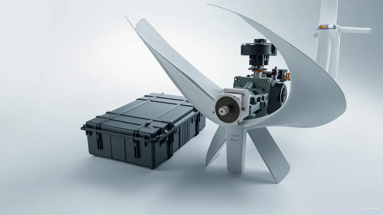
Wind component transport is difficult because it hits three extremes at once: very high unit mass, where gearboxes routinely reach several tonnes to several tens of tonnes; a very long logistics chain, where an inland wind farm may involve road, rail, port, ocean freight and then road again; and harsh environmental conditions spanning high-altitude cold, coastal salt spray, desert heat and wind-blown sand. Combined, these three factors turn wind spare-part protection into a genuine systems engineering problem rather than something a nailed wooden crate can solve.
The geographic distribution of wind projects shapes the supply chain in a particular way. Turbine OEMs are typically located in eastern or northern China, while wind farms may sit in the Gobi desert of the northwest, on offshore islands in the southeast, or overseas. A spare part may spend more than six months in storage and transhipment between leaving the factory and being installed on the tower. For a gearbox, the dominant concerns during that period are bearing false brinelling from micro-movement during storage and lubricant ageing. For blade sensors, they are micro-displacement of fibres and strain gauges and contamination of connectors. For pitch bearings and generators, they are raceway indentations and insulation moisture pickup caused by random vibration.
This article is written for packaging, procurement and logistics engineers at turbine OEMs, blade manufacturers, wind farm operations companies, spare-parts warehouses and overseas wind EPC firms. It breaks down the transport protection requirements for gearboxes, main shafts, blade sensors, pitch and yaw components, generators and tower fasteners, and provides applicable case structures, insert selection guidance, moisture and corrosion control schemes, and test references. The core conclusion is that a wind component case must answer three questions simultaneously: how to suppress the low-frequency vibration response of a large mass, how to stay dry across the entire storage period, and how to maintain sealing effectiveness under salt spray and large temperature differentials.
For wind spare-part packaging programmes, JUNZHJIA (Kexin New Materials (Guangdong) Co., Ltd.) uses a combination of steel frame, rotational-moulded housing and graded inserts to span the range from sensors weighing a few hundred grams to gearbox components weighing several tonnes.
Table of Contents
- 1. Three Challenges of Wind Component Transport: Mass, Chain Length and Extreme Climate
- 2. Gearbox Cases: Vibration and Corrosion Protection for Planetary and Parallel-Shaft Gearboxes
- 3. Main Shaft, Bearing and Coupling Cases
- 4. Blade Sensor Cases: Fibre-Optic Load Sensors, Strain Gauges and Lightning Monitoring
- 5. Pitch and Yaw System Component Cases
- 6. Generator, Slip Ring and Collector Ring Assemblies
- 7. Tower Flange, High-Strength Bolt and Fastener Cases
- 8. Converter and Control Module Cases: Cleanliness, ESD and Moisture
- 9. Vibration Design: From IEC 61400-1 Load Philosophy to Transport Cushioning
- 10. Moisture Control: Long-Term Storage and Condensation
- 11. Corrosion and Salt Spray: The Offshore Requirement
- 12. Sealing and Ingress Protection: IP65, IP67 and Pressure Equalisation
- 13. Case Construction and Insert Selection
- 14. Lifting, Stacking, Markings and Acceptance
- Frequently Asked Questions
- Conclusion & Related Reading
1. Three Challenges of Wind Component Transport: Mass, Chain Length and Extreme Climate
Understanding wind spare-part packaging starts with three differences from ordinary industrial components.
The first is the scale of mass and inertia. A gearbox for a multi-megawatt turbine can exceed 10 tonnes, and its inertial loads in transport far exceed those of typical industrial parts. The case therefore cannot act merely as a wrapper; it must participate in structural load bearing. Support distribution, base stiffness and lifting point positions directly determine the load state of the bearings and gears inside the component.
The second is the length of the logistics chain. Inland wind farms typically require multimodal transport combining road, rail or port, ocean freight and road again, and some overseas projects add inland waterway legs. Every transfer means another lift, another stacking event and another temperature and humidity transition. The cumulative effect deserves more attention than the severity of any single leg.
The third is the span of environmental conditions. One batch of spare parts may see humid heat at the factory, heavy salt spray at sea, high-altitude cold at the wind farm, or desert day-night temperature swings. Offshore wind is the clearest case: components operating inside a nacelle demand very high corrosion protection, yet that requirement is often overlooked during transport and storage, so parts arrive at the wind farm already showing rust spots.
| Component class | Typical items | Dominant failure mode | Protection priority | Key control |
|---|---|---|---|---|
| --- | --- | --- | --- | --- |
| Gearing | Main gearbox, yaw reducer, pitch reducer | Bearing false brinelling, tooth flank rusting, oil degradation | Vibration and moisture | Support distribution, dry air or nitrogen charge, oil sealing |
| Shaft train | Main shaft, main bearing, coupling | Raceway indentations, fit surface corrosion | Vibration > moisture | Axial restraint, journal protection sleeves |
| Sensors | Blade fibre-optic load sensors, strain gauges, accelerometers | Fibre microbending, connector contamination, zero drift | Vibration and cleanliness | Separate cavity, clean-grade foam, dust caps |
| Pitch and yaw | Pitch bearing, drive motor, encoder | Raceway indentations, encoder misalignment | Vibration > moisture | Upright transport, motor-side primary support |
| Electrical | Converter modules, control cabinets, slip rings | Card loosening, condensation, ESD damage | Moisture and vibration | Barrier bag, desiccant, antistatic packaging |
| Fasteners | Tower flange bolts, anchor bolts | Thread damage, coating corrosion, hydrogen embrittlement risk | Cleanliness and moisture | Compartmented trays, anti-rust paper, light and moisture exclusion |
2. Gearbox Cases: Vibration and Corrosion Protection for Planetary and Parallel-Shaft Gearboxes
Gearboxes are the highest-value and most demanding wind spare parts to transport. They contain planetary and parallel-shaft stages, multiple rolling bearings and seals, and leave the factory with precisely matched tooth flank contact and bearing preload. Any abnormal load in transport can disturb those conditions.
Bearing false brinelling is the primary risk. When a bearing sits stationary under vibration for a prolonged period, the roller and raceway contact points undergo very small high-frequency reciprocating micro-movement. Once the lubricant film is broken, micro-pitting forms, appearing as regularly spaced indentations, and noise and vibration values rise accordingly. This damage is hard to detect during unpacking inspection and only emerges after commissioning. Two control paths exist: reduce the vibration magnitude transmitted to the gearbox, and shorten the time the bearing spends stationary.
Reducing vibration magnitude depends on support and cushioning design:
- Use the gearbox base feet or torque arm mounting face as the primary load-bearing surface, never the housing side.
- Provide at least four support points with coplanarity controlled within about 1 mm, so the case does not become a three-point support and introduce additional torque.
- Do not fully encapsulate the gearbox with foam. Lateral restraint plus light top compression at 5 to 8 percent is correct; over-encapsulating a rigid part transmits case distortion into the gearbox.
- For high-precision planetary stages, add an auxiliary damping layer using foams of different densities to suppress low-frequency resonance.
Shortening stationary time is a logistics management matter. Specify a maximum storage period in the technical agreement, after which the gearbox must be re-rotated or the lubrication position changed. For long-term storage, charge the case with dry air or nitrogen at slight positive pressure, and include replaceable desiccant and humidity indicator cards to keep in-case relative humidity below 40 percent. The sealing structure for a charged case is described in how a protective case pressure equalisation valve works.
For offshore gearboxes, both the rust-prevention grade of the lubricant and the internal corrosion protection of the case need to be raised one level, which is covered in section 11.
3. Main Shaft, Bearing and Coupling Cases
Main shafts and main bearings combine a long slender form with high-precision fit surfaces, so their protection priorities differ from gearboxes.
A main shaft is usually a forging and is stiff, but the journal fit surfaces at both ends demand high accuracy, often with cylindricity in the micron range. Any impact forces on-site rework to restore the fit, and that rework changes the fit condition itself. The core requirement of a main shaft case is therefore not cushioning but isolation of the fit surfaces: the journal area must use dedicated protection sleeves in engineering plastic or soft metal, and the case must provide multiple equally spaced supports, ideally not more than 800 mm apart. For shafts longer than about 3 metres, the case needs sufficient longitudinal stiffness, and a steel frame case generally outperforms a plastic housing.
Main bearings are typically large spherical or tapered roller bearings. Their transport protection follows the same logic as gearbox bearings: suppress vibration and avoid prolonged stationary micro-movement. Upright transport also matters, because the rings and rolling elements shift relative to each other under self-weight. Maintain the factory orientation, and provide clamp-type restraint inside the case.
Couplings, including diaphragm and shrink-disc types, fail mainly through diaphragm deformation and corrosion of the shrink-disc fit surfaces. Diaphragm couplings are very sensitive to bending, so the case must provide planar support rather than line support. Shrink disc and taper fit areas should be coated with a neutral anti-rust grease and fitted with protective caps.
When multiple items share one case, follow the principle of separate cavities and a common orientation: all long items laid in the same direction, with dividers between cavities so they cannot strike each other in transit. Removable divider systems work well here, and the design approach is described in removable divider systems for protective cases.
4. Blade Sensor Cases: Fibre-Optic Load Sensors, Strain Gauges and Lightning Monitoring
Blade sensors are the smallest, most expensive and most vibration-sensitive category of wind components. Modern large blades commonly carry fibre Bragg grating load sensors, strain gauges, accelerometers, temperature sensors and lightning monitoring modules for load monitoring and condition assessment.
Their protection requirements are distinctly those of precision instruments.
The core risk for fibre-optic sensors is microbending and end-face contamination. A fibre bent below its minimum radius develops additional loss or breaks outright, so the case must provide enough coiling space for jumpers, with a minimum bend radius of at least 30 mm, using dedicated fibre trays or coiling boxes. Once a connector end face is contaminated or scratched, on-site re-splicing or re-termination is extremely costly, so every connector must be fitted with a dust cap and packed individually in a clean bag.
The risk for strain gauges and lead wires is mechanical damage. Strain gauge leads are extremely fine, and a single pull breaks them. Fix sensors with lead wires into a slotted EVA insert so the wires carry no load and are never bent at a sharp angle.
The risk for accelerometers and inertial sensors is zero drift and over-range damage. These devices contain micromachined structures, and shock above the rated range causes permanent offset. Provide an independent cushioning cavity and size the insert from the sensor's range and allowable shock, generally targeting shock acceleration below 100 g.
When a case holds many sensors, use a two-layer structure of compartmented tray plus individual soft wrap: a rigid outer case for impact resistance, and a compartmented tray with soft foam inside, one sensor per compartment, so they cannot strike each other. Cleanliness calls for clean-grade foam and the avoidance of any material combination that sheds particles. In precision sensor case programmes, JUNZHJIA typically builds the insert as a two-piece set of compartmented tray plus lid compression pad, balancing restraint against ease of handling.
5. Pitch and Yaw System Component Cases
Pitch and yaw systems include pitch bearings, pitch drive motors and reducers, yaw reducers, yaw brakes, encoders and limit switches. They are medium in size, high in precision and numerous, which makes packaging management more complex than the technical challenge itself.
Pitch and yaw bearings are large slewing rings that can reach several metres in diameter. The dominant transport risks are raceway indentations and seal damage. Requirements include transporting with the bearing axis horizontal or in the manufacturer-specified attitude, fitting temporary transport blocks between inner and outer rings to prevent relative rotation, ensuring the seal lip carries no load, and greasing the raceway before packing with a record of the quantity used. For very large bearings, a dedicated transport frame is usually used instead of an enclosed case, and the protection focus shifts to a rain and dust cover, raceway protection band and fixing blocks.
Pitch drive motors and reducers concentrate mass at the motor end. The case should use the motor mounting flange as the primary support surface, with a protective sleeve on the output shaft. Moisture pickup in motor insulation leads directly to a failed on-site withstand test, so moisture control is mandatory, typically through a barrier bag plus desiccant.
Encoders and limit switches are precision small parts. Follow the sensor approach in section 4, pack them individually in soft wraps, and provide spare positions in the case so they can be taken directly to site.
Yaw brakes are hydraulic components, so all oil ports must be plugged, and the effect of low-temperature viscosity change on seals must be considered. For spares destined for cold high-altitude wind farms, the packaging should state the minimum storage temperature.
6. Generator, Slip Ring and Collector Ring Assemblies
The core transport risks for wind generators, whether doubly fed induction or permanent magnet direct drive, are insulation moisture pickup and bearing protection.
Insulation moisture pickup shows up on site as insulation resistance and polarisation index values that fail to meet specification. If a generator sits in a humid environment during transport and storage, the absorbed moisture requires extended drying, which at a wind farm usually means several days of downtime waiting. Countermeasures include sealing the complete unit in a barrier bag with an adequate desiccant charge, placing humidity indicator cards inside the case and reading them at acceptance, and for large generators providing heated air circulation or heating tape inside the case to keep the internal temperature at least 5 degrees Celsius above the dew point.
Bearing protection requires that the rotor cannot rotate freely in transport, which is normally achieved by a rotor locking device. Confirm the locked state before packing and mark on the case exterior that barring is prohibited until the transport locking device is removed. Bearings also need false brinelling protection, following the same approach as gearboxes.
Slip rings and collector ring assemblies contain carbon brushes, conductive rings and insulating supports. Carbon brushes generate dust under vibration, which contaminates insulation surfaces. Remove the brushes and pack them separately, and seal the slip ring body in a dust bag. Where the assembly must travel complete, provide radial restraint inside the case to reduce relative movement between brush and ring.
7. Tower Flange, High-Strength Bolt and Fastener Cases
Tower flange bolts, anchor bolts and connectors look like the least fragile category and are in practice among the most troublesome. High-strength wind bolts carry three risks: thread damage, coating corrosion and hydrogen embrittlement sensitivity.
Thread damage most often results from parts striking each other in transit, particularly in bulk or simply strapped packs. Countermeasures include compartmented trays holding one bolt or one bundle per compartment, plastic thread protection caps, and never allowing free bulk stacking in the case.
Coating corrosion develops quickly in humid and salt-spray conditions. If a zinc-flake, hot-dip galvanised or zinc-aluminium coating is scratched in transit, the scratch becomes a corrosion initiation site. Use vapour phase corrosion inhibitor paper or anti-rust film wrapping with desiccant inside the case, and specify case sealing of at least IP65, or IP67 with a pressure equalisation valve for ocean freight.
Hydrogen embrittlement sensitivity is easily overlooked. High-strength bolts, particularly grade 10.9 and above, are sensitive to hydrogen, and hydrogen introduced by pickling and electroplating requires adequate de-embrittlement treatment. Transport packaging does not change the material condition, but packaging materials that release acidic substances accelerate corrosion and affect subsequent service. Packaging materials should therefore be free of acids, sulphur and chlorine, with compatibility confirmed.
For complete tower bolt sets, pack by tower, one tower per case, with a packing list and installation sequence note inside. This is not only a packaging question but an assembly efficiency question. Compartmented insert design is covered in custom foam insert design guide.
8. Converter and Control Module Cases: Cleanliness, ESD and Moisture
Wind converter and control modules, including converter power units, control cabinet modules, communication modules and remote monitoring units, combine high value, high static sensitivity and high humidity sensitivity. Their protection requirements approach those of precision electronic equipment.
Cleanliness and dust exclusion are baseline requirements. Power module heat sinks, fibre interfaces and signal terminals are very dust sensitive, so use clean-grade foam inside the case and fit dust caps on all interfaces. Heat sink fins must not deform under pressure, and the insert should provide relief in the fin area.
ESD protection must be implemented in practice. Driver boards, control boards and communication cards should go into antistatic shielding bags, plain EPS foam should be avoided inside the case, and antistatic wrist straps should be used during packing and unpacking. Material pairing is covered in ESD shielding case design essentials.
Moisture control follows the same approach as other electrical components: barrier bag, desiccant and humidity indication, with case sealing at IP65 or better. Spares for offshore wind farms also need consideration of salt-spray corrosion on terminals, so a thin layer of neutral protective grease on terminals is advisable.
On vibration, power modules are usually plug-in units inside cabinets, so restrain the complete module in transport. The bulky capacitors and heat sinks inside the module are the main mass concentrations, and the cushioning design should be checked against them. For maintenance spare cases that are transferred frequently, wheels and a trolley handle can reduce handling shock; the structural aspects are covered in case wheels and trolley handle design.
9. Vibration Design: From IEC 61400-1 Load Philosophy to Transport Cushioning
The wind industry has a mature body of structural load and vibration analysis practice, and its central idea, design to an operating spectrum rather than to a single extreme value, applies equally well to transport packaging.
IEC 61400-1 specifies the design requirements for wind turbines, including the classification of load cases and the philosophy behind safety factors. Transport packaging is not directly governed by that standard, but three methodological points transfer.
First, design to a spectrum rather than a point. Real transport excitation is broadband random vibration, and road class, vehicle speed and suspension characteristics determine the power spectral density. Design against a measured road spectrum or a standard spectrum such as those in the ISO 13355 and GB/T 4857 series, not against a single drop height.
Second, focus on resonance rather than peak value alone. A large component combined with a cushion layer often produces a resonance peak with a high amplification factor between 5 and 20 Hz, precisely the band where road transport energy concentrates. Remedies include adjusting support stiffness, layering foams of different densities, and adding isolation pads between case and transport frame. For gearboxes in the multi-tonne class, controlling the system natural frequency is usually more effective than adding foam thickness.
Third, split the objective across two protection levels. The first level is the case and base, which carry stacking and lifting loads. The second is the insert, which holds acceleration transmitted to the component below its allowable value. The two levels have different objectives and should use different materials and structures; conflating them is a common error.
For test verification, complete at least random vibration, drop and shock, and stacking. Methods and pass criteria are covered in how to select and run ISTA transport testing procedures. Where a project requires environmental robustness assessment, the vibration, shock and humidity methods of MIL-STD-810H can be referenced, bearing in mind that the standard is used purely as a test-method reference and does not represent any military certification of the product. Correct wording is explained in MIL-STD-810H and protective case environmental testing.
10. Moisture Control: Long-Term Storage and Condensation
Wind spare parts are stored far longer than typical industrial components, which raises the weight of moisture-control design considerably. A system suited to long-term storage has four layers.
The first layer is the barrier. Aluminium-foil composite film with a PET/AL/PE structure typically delivers a water-vapour transmission rate around 0.1 g per square metre per 24 hours, making it the most cost-effective option for medium-volume items such as gearbox accessories, sensors and control modules. For very large items such as a complete gearbox, a barrier bag is impractical, and the approach shifts to charging with dry air or nitrogen and holding slight positive pressure.
The second layer is the desiccant. Silica gel and molecular sieve are common. Capacity is estimated from free volume inside the case and the target humidity, with an engineering rule of thumb of 0.5 to 1.0 kg of silica gel per cubic metre of free volume. For long-term storage, double the charge per replacement cycle and define replacement points. Desiccant should be suspended from the upper part of the case, not touching the component, grease or coatings.
The third layer is humidity indication. Place at least three points, at both ends and the middle of the case. For long-term storage, a recording temperature and humidity data logger is strongly recommended, because it lets the whole storage history be reviewed at unpacking, which is extremely valuable for quality traceability.
The fourth layer is structural sealing. Keep gasket compression between 25 and 35 percent, and select a material that tolerates low temperature. Storage at cold high-altitude wind farms can reach minus 40 degrees Celsius, where ordinary nitrile rubber hardens and loses elasticity, so silicone or EPDM should be specified. Material behaviour at extreme temperatures is covered in protective case design for extreme temperature environments.
One reminder: a case in long-term storage must be opened periodically to replace desiccant and check for condensation traces. Many cases of parts arriving already rusted trace back to packaging that was never maintained during storage.
11. Corrosion and Salt Spray: The Offshore Requirement
Spares for offshore and coastal wind farms need additional salt-spray consideration. Chloride ions break down the passive film on metal surfaces, and even stainless steel can suffer pitting.
For case materials, rotational-moulded HDPE performs well against salt spray and is the first choice offshore. Steel frame cases require hot-dip galvanising or a heavy-duty coating system, for example an epoxy zinc-rich primer with epoxy intermediate and polyurethane topcoat, selected according to the corrosivity category in ISO 12944. Aluminium parts should be anodised.
Hardware is the weakest link. Use 316 stainless steel hinge pins, and apply corrosion protection to latches, rivets and fasteners. The assembly should pass at least 96 hours of neutral salt spray without red rust; for long-term offshore storage, raise the target to 240 hours or more.
Protecting the component itself matters equally. Unpainted surfaces on gearboxes such as machined faces, keyways and threaded holes should be coated with neutral anti-rust grease. Sensors and electrical connectors should use sealed connectors or protective caps. Bolts should use VCI anti-rust packaging.
For the internal environment, external moisture in a salt-spray environment carries chloride ions, which makes the barrier layer even more important. Seal critical components individually in aluminium-foil barrier bags, provide desiccant and humidity indicator cards inside the case, and mark the case exterior with an offshore transport designation and the required storage period.
12. Sealing and Ingress Protection: IP65, IP67 and Pressure Equalisation
Under IEC 60529 and GB/T 4208, the selection logic for wind component cases is as follows.
| Rating | Dust | Water | Typical application | Notes |
|---|---|---|---|---|
| --- | --- | --- | --- | --- |
| IP54 | Partial dust protection | Splash resistant | In-plant movement, covered warehouse | Short haul and indoor only |
| IP65 | Dust tight | Water jet resistant | Inland wind farm road transport | Common baseline for electrical parts |
| IP67 | Dust tight | Temporary immersion, 1 m for 30 min | Ocean freight, open yards, coastal wind farms | Use with a pressure equalisation valve |
| IP67 plus valve | Dust tight | Immersion plus differential pressure equalisation | Offshore wind, long trans-climate shipments | Best overall protection |
Three points deserve emphasis. First, an IP rating does not cover salt spray, cushioning or internal humidity; it is a water and dust ingress metric and must not be treated as the complete measure of protection. Second, large-volume cases should provide pressure equalisation, because the pressure differential from day-night temperature swings grows with volume, and a fully sealed case draws external moist air in as it cools. Third, low temperature affects sealing performance: silicone and EPDM retain useful elasticity at minus 40 degrees Celsius, while ordinary nitrile rubber hardens significantly and sealing fails. Spare cases for cold high-altitude wind farms should state the minimum service temperature of the gasket material. Structural and verification details for IP67 are covered in IP67 protective cases: structure, sealing and verification.
13. Case Construction and Insert Selection
Wind component cases span a wide range of constructions and must be selected by mass and size.
| Component tier | Typical mass | Recommended construction | Insert approach | Key structural requirements |
|---|---|---|---|---|
| --- | --- | --- | --- | --- |
| Small precision parts | 0.1-10 kg | Injection-moulded PP or ABS case | EVA compartmented tray plus lid compression pad | Clean foam, dust caps, separate cavities |
| Medium parts | 10-200 kg | Rotational-moulded HDPE case | EVA or PE profiled insert | Multiple support points, replaceable gasket |
| Large parts | 200 kg to 3 t | Rotational-moulded case with steel base | Local profiled saddles plus restraint blocks | Lifting points, forklift pockets, stacking strength test |
| Very large parts | Above 3 t | Steel frame transport frame with cover | Support saddles plus raceway and journal protection | Support coplanarity, axial end stops, lifting plan |
Insert materials follow the same differentiated logic:
| Material | Density (kg/m3) | Characteristics | Suitable components |
|---|---|---|---|
| --- | --- | --- | --- |
| Closed-cell EVA | 60-120 | High resilience, dimensionally stable, easy to profile | Precision sensors, control modules, profiled saddles |
| Closed-cell PE | 25-70 | Good energy absorption, low cost | Base pads for large parts, end buffer blocks |
| PU foam | 20-60 | Good damping, effective mid and high frequency isolation | Precision parts needing resonance suppression |
| EPP moulded parts | 30-60 | Excellent resilience, complex three-dimensional geometry | Volume production profiled inserts |
| Laminated assemblies | Varies | Stiffness designed in stages | Graded cushioning for high-mass parts |
The pairing principle is rigid outside, soft inside, graded energy absorption, resonance avoidance. The standard approach for wind programmes at JUNZHJIA is a rotational-moulded HDPE housing for weather and impact resistance, a steel base that carries stacking and lifting loads, EVA profiled saddles for geometric restraint, and PE end buffer blocks for energy absorption. Hardware is designed for long service life with replaceable hinges, latches and gaskets, as described in toolbox hinge, latch and gasket structure explained and case foam material comparison and selection.
14. Lifting, Stacking, Markings and Acceptance
Lifting and stacking are where wind component cases sustain the most damage. Five marking groups and five rules apply.
Five marking groups:
- Centre of gravity, indicated in longitudinal, transverse and vertical directions.
- Lifting point positions with a lifting angle diagram, plus a warning against lifting the case by component lifting lugs.
- Permitted stacking layers, or a do-not-stack instruction.
- Transport locking device status and removal method, mandatory for gearboxes, generators and bearings.
- Handling symbols to GB/T 191 for keep-dry, this-side-up, fragile and off-centre gravity.
Five rules:
- Case top compressive strength must match the marked stacking layers, verified by physical stacking test.
- When cases of different sizes are mixed, heavy cases go at the bottom, and a large case must not bridge across the mid-span of a smaller one.
- Long items such as main shafts and blade components require axial end stops.
- Never lift the case by the component's own lifting lugs, and never lift at an angle.
- Stacking inside a sea container must be designed around actual accelerations and lashing points, and lashing must not bear on component load faces or sealing faces.
Acceptance should run in three stages. At the drawing stage, lock down the insert layout, restraint points, lifting points and markings. At the sample stage, carry out physical loading and a short-haul transport trial. At batch stage, combine variable inspection of critical dimensions, attribute inspection of appearance, and batch-level type verification of materials. A worked sampling approach is given in custom case acceptance and AQL sampling methods.
The documentation package should include case and foam material certificates with density and UL94 flammability grade, gasket material and low-temperature flexibility data, ingress protection self-test or third-party reports, vibration, drop and stacking test reports, a packing work instruction covering transport locking device operation and removal, a spare parts list and a storage maintenance procedure. For wind projects, JUNZHJIA can supply this package against a customer acceptance checklist and coordinate third-party inspection on a sampling basis.
Frequently Asked Questions
Q: How does bearing false brinelling occur in wind gearbox transport, and how is it avoided?
A: False brinelling, or fretting corrosion, occurs when a bearing sits stationary under vibration: the roller and raceway contact points undergo very small high-frequency reciprocating movement, the lubricant film in the contact zone breaks down, and micropitting appears on the metal surface as regularly spaced indentations. Two conditions are required, vibration and stationarity, so there are two corresponding countermeasures. The first is reducing the vibration magnitude transmitted to the gearbox: use the base feet or torque arm mounting face as the primary load-bearing surface, provide at least four support points with coplanarity within about 1 mm, do not fully encapsulate the gearbox with foam but apply lateral restraint plus light top compression at 5 to 8 percent, and for high-mass units layer foams of different densities to suppress low-frequency resonance. The second is shortening the stationary period: specify a maximum storage duration in the technical agreement, after which the gearbox must be re-rotated or its lubrication position changed. For long-term storage, charge the case with dry air or nitrogen at slight positive pressure and keep in-case humidity below 40 percent using desiccant and indicator cards.
Q: What matters most when transporting blade fibre-optic load sensors?
A: Three points dominate. First, the fibre bend radius: a fibre bent below its minimum radius develops additional loss or breaks, so the case must provide coiling space for jumpers with a minimum bend radius of at least 30 mm, using dedicated fibre trays or coiling boxes. Second, connector end-face protection: contamination or scratching forces on-site re-splicing or re-termination, with significant cost and schedule consequences, so every connector must have a dust cap and be packed individually in a clean bag. Third, mechanical protection of strain gauge leads: leads are extremely fine and break under a single pull or a sharp bend, so sensors with leads should be fixed into a slotted EVA insert where the wires carry no load. In addition, sensors containing micromachined structures such as accelerometers are sensitive to over-range shock, which causes permanent offset, so provide an independent cushioning cavity and target shock acceleration below 100 g. When a case holds many sensors, use a two-layer structure of compartmented tray plus individual soft wrap, one sensor per compartment, so they cannot strike each other.
Q: How can moisture protection be made to last through a long wind spare-part storage period?
A: Four layers must all be present. The first is the barrier: for medium-volume items, an aluminium-foil composite bag with a PET/AL/PE structure at a water-vapour transmission rate around 0.1 g per square metre per 24 hours, vacuum-drawn or dry-air filled and heat sealed; for very large items that cannot be bagged, charge with dry air or nitrogen at slight positive pressure. The second is desiccant: charge at the engineering rule of thumb of 0.5 to 1.0 kg of silica gel per cubic metre of free volume, double the charge per cycle for long-term storage, define replacement points, and suspend the desiccant from the upper part of the case away from components and coatings. The third is humidity indication: at least three indicator cards inside the case, plus a recording temperature and humidity logger so the entire storage history can be reviewed at unpacking, which is highly valuable for traceability. The fourth is structural sealing: gasket compression of 25 to 35 percent, with a material that tolerates low temperature, ideally silicone or EPDM rather than ordinary nitrile rubber for cold sites. One final point is often missed: a case in long-term storage must be opened periodically to replace desiccant and check for condensation, because many parts arriving already rusted were in packaging that was never maintained.
Q: What level of salt-spray protection is needed for offshore wind spare-part cases?
A: Address four levels simultaneously. For the case, rotational-moulded HDPE performs well against salt spray and is the first choice offshore; steel frame cases need hot-dip galvanising or a heavy-duty coating system selected to the ISO 12944 corrosivity category, for example an epoxy zinc-rich primer with epoxy intermediate and polyurethane topcoat; aluminium parts should be anodised. Hardware is the weakest link, so use 316 stainless steel hinge pins and apply corrosion protection to latches, rivets and fasteners, targeting at least 96 hours of neutral salt spray without red rust, or 240 hours and above for long-term offshore storage. For the component itself, coat unpainted gearbox machined faces, keyways and threaded holes with neutral anti-rust grease, use sealed connectors or protective caps on electrical connectors, and pack bolts in VCI anti-rust materials. For the internal environment, remember that external moisture under salt spray carries chloride ions, so seal critical components individually in aluminium-foil barrier bags, provide desiccant and humidity indicator cards inside the case, and mark the case exterior with an offshore designation and the required storage period.
Q: For multi-tonne items such as wind gearboxes, is an enclosed case or a transport frame the better choice?
A: It depends on the logistics chain and protection requirement, and the two are not mutually exclusive. In general, components above several tonnes that are geometrically regular and principally structural, such as a complete gearbox, a large slewing bearing or a main shaft, suit a steel frame transport frame with local protective covers. The reason is that an enclosed case at that scale is very costly and adds substantial tare weight, whereas a transport frame participates directly in structural load bearing, and protection is equally reliable provided support coplanarity, axial end stops and the lifting plan are controlled. A frame solution must additionally address three things: rain and dust exclusion through a cover or stretch wrap plus desiccant, local protection of precision surfaces such as raceways and journals using sleeves and anti-rust grease, and management of transport locking device status. Conversely, if a component must be stored long term at a wind farm warehouse, or will pass through multiple transfers and open storage, a rotational-moulded case with a steel base is preferable, balancing sealing against structural strength. Real projects often use a hybrid: transport frames for the main component and enclosed cases for precision accessories such as sensors, encoders and control modules.
Q: How should the ingress protection rating be chosen for wind component cases, and is IP65 sufficient?
A: The deciding factors are the transport route and storage conditions, not the value of the component. Three questions give a quick answer: does it travel by sea or along the coast; is it stored in the open; could it encounter standing water or washdown? If any answer is yes, specify IP67. For purely inland wind farms with covered warehouses and short road hauls, IP65 is entirely adequate and costs 15 to 25 percent less. Two aspects specific to wind projects deserve attention. First, case volume is large, so the pressure differential created by day-night temperature swings is more pronounced, and a fully sealed case draws external moist air in as it cools; specifying IP67 with a pressure equalisation valve usually outperforms plain sealed IP67. Second, low temperature affects gasket material, since storage at cold high-altitude sites can reach minus 40 degrees Celsius where ordinary nitrile rubber hardens and loses elasticity, so silicone or EPDM should be used. It is also essential to understand that an IP rating covers water and dust ingress only; salt-spray corrosion, cushioning performance and internal humidity control all require separate design.
Q: What special requirements apply to converter and control module cases?
A: Converter power units and control modules combine high value, high static sensitivity and high humidity sensitivity, so requirements approach those of precision electronic equipment. On cleanliness and dust, power module heat sinks, fibre interfaces and signal terminals are dust sensitive: use clean-grade foam inside the case, fit dust caps on all interfaces, and relieve the insert in the heat sink fin area to prevent deformation under pressure. On ESD, use antistatic shielding bags for driver, control and communication boards, avoid plain EPS foam inside the case, and require antistatic wrist straps during packing and unpacking. On moisture, combine a barrier bag with desiccant and humidity indicators, with case sealing at IP65 or better; offshore spares also need a thin layer of neutral protective grease on terminals to resist salt spray. On vibration, power modules are usually plug-in units, so restrain the complete module in transport, and check the cushioning design against the bulky capacitors and heat sinks that form the main mass concentrations inside the module. For maintenance spare cases transferred frequently, wheels and a trolley handle can reduce handling shock.
Q: What support can JUNZHJIA provide for wind component transport cases?
A: JUNZHJIA (Kexin New Materials (Guangdong) Co., Ltd.) supports turbine OEMs, blade manufacturers, wind farm operations companies and overseas wind EPC firms in four areas. First, component-specific protection schemes: using the dimensions and mass of gearboxes, main shafts, blade sensors, pitch and yaw components and control modules, the team designs rotational-moulded cases, steel bases, transport frames or enclosed case solutions, and issues insert section drawings with restraint point load-path explanations. Second, insert and case fabrication: EVA, PE, PU and EPP inserts are selected per component, with compartmented trays, profiled saddles, lid compression pads and removable dividers available, and housings offered in injection-moulded, rotational-moulded and metal frame constructions. Third, protection and testing: IP65 and IP67 verification can be completed to IEC 60529 and GB/T 4208, pressure equalisation valves, desiccant and humidity indication systems can be configured, low-temperature gasket materials can be specified, and third-party random vibration, drop, stacking, salt spray and humidity cycling testing can be coordinated with reports. Fourth, OEM and ODM supply with global delivery, including customer branding, packing work instructions covering transport locking procedures, and long-term spare-part supply.
Conclusion & Related Reading
The difficulty of wind component transport protection is that it simultaneously demands structural strength, vibration control, long-term moisture resistance and corrosion resistance, and these requirements pull against each other. Increasing structural strength raises stiffness, which can amplify resonance; improving sealing worsens the breathing effect; raising the corrosion class increases cost. The answer is not to add material in any one dimension but to separate the case, the base and the insert into clearly defined functional layers, each responsible for one thing, and to use test data as the verification interface between layers.
The practical sequence has four steps. At the design stage, fix the support points, restraint points and lifting points and check system resonance. At the sample stage, carry out physical loading and a short-haul transport trial. During storage, establish a desiccant replacement and inspection cycle. At acceptance, write materials, testing and the documentation package into the technical agreement. Do these four things and the hidden damage that accumulates across a long wind supply chain can be substantially reduced.
Related Reading