

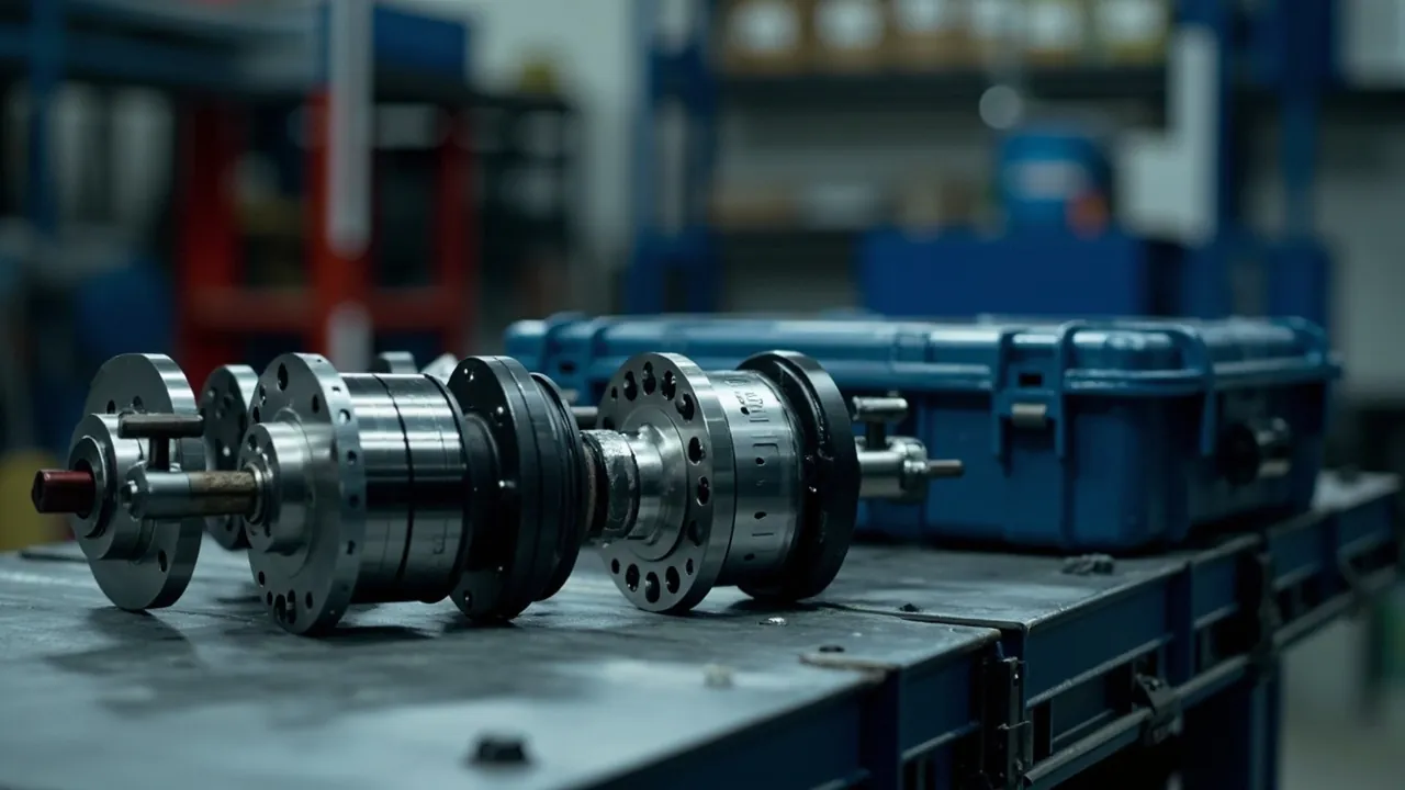
What actually threatens a shaft coupling in transit is not a knock. It is micron-scale deformation and dimensional instability. A disc pack is a stack of thin stainless steel plates acting as an elastic element, and any bending beyond its elastic limit permanently changes its stiffness characteristics. Flange spigots and bolt holes are locating datums, and a few microns of ovality or a scratch is enough to make on-site assembly miss the designed coaxiality. The keywords for coupling packaging are therefore end-face restraint, compartment isolation, and no axial compression, substituting face contact for stacked squeezing and dedicated compartments for mutual support.
A representative field incident makes the point. A batch of disc couplings shipped in cartons with bubble wrap arrived with no visible external damage. Two weeks after installation, vibration readings began climbing steadily. Teardown showed plastic deformation in the disc packs, and the transport trail revealed the cartons had been crushed at the bottom of a pallet, subjecting the discs to sustained static load that produced creep and bending. The entire batch had to be downgraded or scrapped, at a loss far exceeding the packaging cost.
This article is written for transmission component manufacturers, mechanical parts traders, and equipment builder purchasing staff. It works through the sequence of deformation mechanics, dimensional preservation, support design, compartmented inserts, corrosion and contamination control, test acceptance, and on-site inspection, giving a design method and pass criteria for coupling cases, and closing with the practical points of model family management and volume supply.
Table of Contents
- Why Coupling Transport Risk Centers on Deformation Rather Than Impact
- The Mechanical Limits of Disc Packs and Elastic Elements
- Preserving Flange Spigots, Bolt Holes, and Keyways
- Support Strategies for Spacer Shafts and Long-Span Couplings
- Compartmented Inserts and End-Face Restraint Design
- Corrosion Protection for Steel Flanges and Contamination Control for Stainless Parts
- How Balance and Cleanliness Requirements Constrain Packaging
- Case Selection, Load Capacity, and Stacking Calculations
- Transport Test Plan and Pass Criteria
- Pre-Installation Inspection Checklist
- Marking, Traceability, and Volume Supply Systems
- Model Family Management and Selection Decisions
- Frequently Asked Questions
- Conclusion and Related Reading
Why Coupling Transport Risk Centers on Deformation Rather Than Impact
A coupling is a classic stiffness-sensitive component. Its performance metrics, including torsional stiffness, permissible misalignment, and balance grade, all rest on the geometric accuracy of elastic elements and mating faces. The failure logic differs from that of gears or shafts. A gear fears tooth surface damage and a shaft fears bending, but a coupling fears the drift of dynamic characteristics caused by tiny geometric change.
Three classes of change are the most damaging.
The first is plastic bending of the disc pack. Discs are typically stacked from stainless steel sheet between 0.2 mm and 0.5 mm thick, designed to operate in pure elastic bending. Once a transport load bends the disc out of plane, even if it springs back at the time, residual deformation can remain, producing asymmetric stiffness and generating parasitic axial force during torque transmission.
The second is deformation of flange mating faces. The flange spigot, a locating cylindrical surface, and the flange face are the assembly datums, usually specified with a transition or interference fit. If a flange is squeezed, stacked under load, or over-tensioned by strapping during transit, spigot roundness goes out of tolerance and assembly either fails outright or produces initial eccentricity when forced.
The third is change in bolt hole size and position. High-strength couplings use tightly toleranced bolt holes, and a burr at a hole edge directly affects the uniformity of bolt preload and therefore the reliability of torque transmission.
A practical test of whether packaging is adequate is simple: no component inside the case may carry sustained external load. Stacking, strapping, and mutual support all create sustained load. Under sustained load metal does not have to yield immediately, because long-term creep produces the same accuracy drift.
The Mechanical Limits of Disc Packs and Elastic Elements
The disc pack is the most delicate part of a coupling and it sets the constraints for the packaging design.
The important characteristic is directional. A disc is strong in the torsional direction, where it transmits torque and weak out of plane, meaning the bending direction perpendicular to the disc surface. This means that if the flange faces are loaded axially in the package, that load passes through the bolts and spacers directly into the disc pack's weakest axis.
Two hard design rules follow:
- Never compress the disc pack axially. End restraint must act on the flange outer diameter or the flange back face, never by clamping the disc region to prevent axial movement.
- Never let the coupling's own weight hang on the discs. In a vertical orientation, support must act on the lower flange, and the upper flange must not be suspended through the disc pack.
Fragility differs noticeably between elastic element types, and the table below can serve as a grading basis.
| Elastic Element | Structure | Transport Weak Point | Fragility | Packaging Emphasis |
|---|---|---|---|---|
| --- | --- | --- | --- | --- |
| Stainless disc pack | Stacked thin plates | Out-of-plane plastic bending | High | No axial compression, isolated compartment |
| Single-disc coupling | One large diameter disc | Edge warping | Medium-high | Flat support, no edge loading |
| Bellows coupling | Thin-wall metal bellows | Lateral crushing | High | Radial clearance, no side pressure |
| Jaw and spider coupling | Engineering plastic spider | Compression set in the spider | Medium | Avoid long-term compression |
| Curved-tooth gear coupling | Tooth engagement | Tooth impact, grease loss | Medium | Tooth protection, grease retention |
| Rigid flanged coupling | Solid flange | Spigot impact damage | Low | Spigot and face protection |
| Oldham coupling | Intermediate disc | Wear surface scoring | Medium | Independent fixing of the disc |
A useful order of magnitude: the permissible out-of-plane displacement of a disc pack within its elastic range is typically a fraction of a millimeter, and the corresponding bend angle before the elastic limit is small. If the packaging leaves 3 mm to 5 mm of free play, a single impact is enough to push the disc beyond its elastic range. This means that leaving some margin, which is sensible for most machined parts, is precisely the risk source for a disc coupling.
Preserving Flange Spigots, Bolt Holes, and Keyways
The flange is the coupling's assembly interface, and preserving its dimensions determines whether on-site assembly proceeds smoothly. The protected features and the corresponding measures are listed below.
| Feature | Precision Character | Main Risk | Packaging Measure | Verification Method |
|---|---|---|---|---|
| --- | --- | --- | --- | --- |
| Flange spigot OD | Locating fit surface | Impact, squeeze deformation | Ring clearance in insert, no contact | Roundness with micrometer |
| Flange face | Flatness datum | Scratches, compression marks | Face inward or isolated from hard parts | Straight edge or surface plate |
| Bolt holes | Position and diameter | Edge burrs, deformation | Protective plugs or bolt sleeves | Go and no-go gauges |
| Keyway | Lateral fit surface | Edge rollover | Keyway filler block | Plug gauge |
| Taper seat | Taper and contact ratio | Scoring, corrosion | Taper sleeve plus grease film | Blueing check |
| Exposed journal | Roundness and roughness | Corrosion, impact | Journal sleeve plus VCI | Micrometer check |
One low-cost measure deserves wider use: fill bolt holes with dedicated protective plugs or temporary bolts. This prevents edge damage and simultaneously provides additional locating support for the insert, serving two purposes. For high-precision couplings, the bolt holes themselves can serve as load-bearing support points for the insert, shifting support away from the disc region and onto the flange body, neatly avoiding the fragile zone.
Keyway protection is another detail. Keyway edges roll over easily during handling, and after rollover the key becomes difficult to insert. On site the usual response is to dress the edge with a file, which enlarges the fit clearance. Fill the keyway with a matched filler block or a soft filler strip and remove it after transport.

Support Strategies for Spacer Shafts and Long-Span Couplings
For long-span couplings with a spacer shaft, common in pump sets, compressors, and large fan drives, the support design is far more complex because there is an additional slender shaft to manage.
Support point layout principles:
- Provide one support at each end of the spacer shaft, close to but not touching the flange spigot.
- Add a mid support when the spacer shaft exceeds 1 m, and consider three or more support points beyond 2 m.
- Use a stiffer material for the support blocks, such as hard EVA, engineering plastic, or a soft-faced wooden block. Avoid soft foam alone, because it compresses continuously under the shaft's own weight, so late in the journey the supports sink and the shaft sags.
- Cover the contact surface with a soft layer so a hard support cannot polish the journal under vibration.
Horizontal or vertical orientation. Long-span couplings can generally only be laid horizontally, and in that position the spacer shaft's own weight produces sag between supports. If the support spacing is too large, the sag stays within the elastic range but partial solidification through creep occurs over long static periods. The key to horizontal placement is therefore controlling support spacing, not adding cushion thickness. As an experience rule, keeping adjacent support spacing within one third of the spacer shaft length effectively controls sag.
Connection state at the flanges. If the coupling is assembled as a complete unit at the factory, with flanges already joined to the spacer shaft, the package must treat it as one rigid assembly. Note that if the two end supports have different stiffness, an additional bending moment appears at the connecting bolts. Use identical structure, material, and compression at both ends.
Compartmented Inserts and End-Face Restraint Design
The insert is the working element of a coupling case, and its design proceeds in four steps.
Step one: establish the datum. Use the flange outer diameter or the flange back face as the locating datum, avoiding the disc region and the spigot mating surface.
Step two: divide the compartments. When several couplings ship in one case, compartments are mandatory. The options and their applicability appear below.
| Compartment Method | Construction | Advantage | Risk | Suitable Situation |
|---|---|---|---|---|
| --- | --- | --- | --- | --- |
| Fully formed compartments | One insert machined with several cavities | High locating accuracy, complete isolation | Model-specific, rework on redesign | Fixed models in volume |
| Modular assembly | Standard modules assembled into cavities | Adapts to many models, reconfigurable | Modules must be fixed against shift | Many models, small batches |
| Divider boards | Flat dividers plus individual soft pads | Simple and low cost | The divider itself can transmit shock | Large, lower-precision parts |
| Layered trays | One tray per layer with a load-bearing plate between | Easy handling, flexible count | The interlayer plate must be stiff enough | Multiple units of one size |
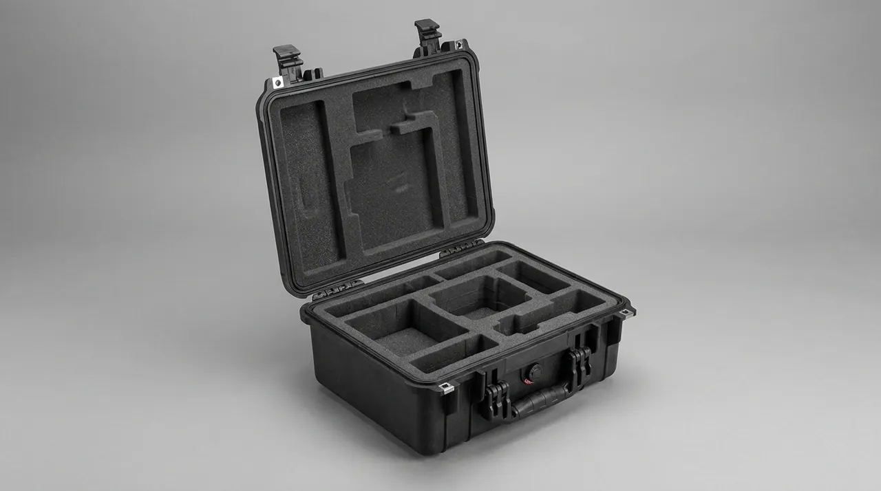
Step three: build the end-face restraint. End restraint is the core of coupling packaging. The restraining face should act on the flange back face or an outer diameter step, with the largest possible contact area, holding axial displacement within 0.5 mm. Restraint must exist on both the lid insert and the base insert so they press against each other; otherwise the constraint is lost the moment the case is tipped.
Step four: provide a handling path. Design finger slots or lifting tabs so parts can be placed and removed by hand. This looks minor but matters a great deal in practice: if extraction requires prying, the site will use a screwdriver against the flange face and produce scratches directly.
For materials and processes, use EVA for load bearing and precision locating, and EPE or PU for the outer cushioning layer. For shaped cavity machining and tolerance control, see custom foam insert fabrication and tolerance control, and for material performance comparison, see protective case foam material comparison and selection.
Corrosion Protection for Steel Flanges and Contamination Control for Stainless Parts
Couplings often combine different metals, which creates two opposite corrosion and contamination problems.
Corrosion protection for carbon and alloy steel flanges. An untreated carbon steel flange develops rust spots quickly once humidity passes a threshold, and a rust spot on a spigot or face renders the part unusable. Apply three layers of protection: a thin corrosion-preventive film covering spigots, faces, and keyways; vapor-phase corrosion inhibitor material; and desiccant control of internal humidity. Size desiccant by free internal volume, using 250 g to 500 g per 100 L as an experience value with a multiplier for transit duration. For moisture vapor transmission and compatibility of seal materials, see protective case seal material types and matching scenarios.
Contamination control for stainless parts. Stainless discs resist corrosion on their own, but one risk is easily overlooked: carbon steel dust or iron filings deposited on a stainless surface cause pitting in humid conditions. Once pitting begins it becomes a fatigue crack initiation site, and a disc is exactly the kind of part that carries alternating stress. The packaging environment must therefore be clean. Clean inserts before use, never reuse an insert that has previously held carbon steel parts and retains iron filings, and never place unprotected carbon steel loose parts in the case.
Dissimilar metal contact. Where a flange is carbon steel, a disc is stainless, and bolts are alloy steel, the contact interfaces can support galvanic corrosion in humid air. Ensure the corrosion-preventive film covers every dissimilar metal interface, and where possible separate them with insulating washers or barrier film.
Grease retention. Gear couplings are greased at the factory, and transit must prevent grease loss and contamination. Avoid high temperature, keep the case interior clean, and verify grease quantity after transport.
How Balance and Cleanliness Requirements Constrain Packaging
Some couplings, especially high-speed units, are balanced before shipment, and some carry balance weights or balance marks. This imposes two additional constraints.
Constraint one: mass distribution must not change. Packaging material residue, such as tape, labels, or foam fragments, adhering to the coupling destroys the balance work already performed. Never apply tape directly to the coupling body or to balance weights; fixing must come from insert cavity geometry rather than adhesion. After unpacking, inspect the body surface visually for residue and clean with a lint-free cloth where necessary.
Constraint two: balance marks must not be obscured. Balance marks and weight positions must be visible on site for phase alignment during installation. The packaging design must not hide them behind the insert to the point of being unreadable; provide a viewing window in the insert where needed.
On cleanliness, when a coupling serves a cleanroom environment in semiconductor, pharmaceutical, or display manufacturing, or serves food machinery, particle shedding and migration from packaging materials become the focus. Measures include specifying low-shedding packaging materials, wiping the case exterior before opening outside the clean environment, and supplying cleanroom packaging instructions. Align cleanliness classes with the ISO 14644 series and specify the required opening environment class in the technical agreement. For electronics assembly and other static-sensitive areas, the packaging needs static dissipative capability, as described in ESD shielding case design and material selection.
Case Selection, Load Capacity, and Stacking Calculations
Couplings are heavy and concentrated cargo, so case design revolves around load capacity and center of gravity.
Load calculation. Calculate the bottom case as carrying the total load of three to five cases above it, and require the walls to carry it. If stacking load ultimately reaches the couplings in the bottom case, the result is sustained compression, precisely the cause of the creep and bending incident described earlier. Apply a safety factor of 2 to 3 as an experience value to approximate dynamic amplification.
Division of labor between wall and insert. A clear principle applies: the wall carries load and seals, and the insert cushions and locates. If the insert carries stacking load, the foam must compress and the constraint fails.
Hinges, latches, and gaskets. For returnable cases, these three areas deserve attention. Hinge pins must be captive, latches should have secondary locking, and gaskets should preferably be molded silicone or EPDM with compression controlled between 30% and 40%. For the structural forms, see toolbox hinge, latch, and seal structure explained.
Handling and lifting. Cases above roughly 40 kg should have wheels and a telescoping handle, and above 80 kg should have lifting points with prohibited fork contact areas identified. A common way coupling cases are damaged is a forklift tine pressing against a flange in the bottom layer, so the case base needs enough structural depth to separate the tines from the insert.
Protection rating. Among common IP levels, IP55 suits covered transport and in-plant transfer, IP65 suits sea freight and outdoor storage, and IP67 suits open yard stacking and wet transfer. Note that IP ratings describe dust and water only and are unrelated to shock and vibration resistance. For sealed cases crossing climate zones, fit a pressure equalization valve to prevent seal deformation or moisture uptake through breathing, as covered in the role and selection of pressure equalization valves in protective cases.
Transport Test Plan and Pass Criteria
For couplings, the point of transport testing is that the part remains undeformed, not merely that the case survives.
Recommended test set:
- Temperature and humidity conditioning per GB/T 4857.2, covering the actual transport climate.
- Vibration testing, preferably random rather than fixed frequency, so the test cannot accidentally avoid the resonance region and produce a false pass.
- Drop testing, with height set by package weight and handling method, focusing on corner, edge, and face drops.
- Compression testing per GB/T 4857.3, checking wall strength and whether the insert collapses.
- Full package performance per ASTM D4169 distribution cycle where the customer requires it.
Pass criteria, measured on the part rather than the case:
- No visible plastic deformation or flatness change in the disc pack.
- Flange spigot roundness and face flatness unchanged from factory values.
- Bolt holes pass go and no-go gauging with no edge burrs.
- Assembly coaxiality still meets the design requirement.
- Balance state unchanged, re-measured where facilities allow.
- No scratches, rust spots, or foreign material residue on surfaces.
Item 4 is closest to real use, and a simulated assembly after testing is recommended. If assembly coaxiality is out of tolerance after testing, the design should be rejected even when the exterior looks perfect.
For general package performance requirements, see GB/T 4857 transport package test methods explained, and where a customer specifies distribution cycle allocation, see ASTM D4169 distribution cycle testing and protective case validation.

Pre-Installation Inspection Checklist
A coupling is a component that is hard to remove once installed, so inspection before installation delivers the lowest-cost verification. Supply the following checklist with the case.
Step one: appearance and corrosion
- Rust spots, scratches, or burrs on the spigot and face
- Deformation, warping, or compression marks in the disc pack
- Packaging residue on surfaces, which would disturb balance
- Keyway edge rollover
Step two: dimensions and fits
- Spigot outer diameter and roundness
- Face flatness
- Bolt hole go and no-go gauging
- Taper contact ratio by blueing where applicable
Step three: condition confirmation
- Completeness and count of bolts, washers, and other accessories
- Grease quantity in gear couplings
- Balance marks and weights intact and identifiable
Step four: installation and alignment
- Complete alignment to the specified coaxiality and record readings
- Tighten bolts to specified torque in the specified sequence
- Re-measure alignment, since values shift after tightening
- Run and observe vibration and temperature rise
The first two steps are the critical ones. Spending ten minutes on dimensional re-verification before installing a coupling saves an order of magnitude more time than removing and redoing the job afterward.
Marking, Traceability, and Volume Supply Systems
Couplings are usually supplied in pairs or sets, so the marking system directly affects correct pairing at the installation site.
Unit marking should include: model and size, factory serial number, disc pack model and batch, balance mark, and manufacturing date.
Case marking should include: product name and model, quantity and set relationship such as drive side and driven side, net and gross weight, case dimensions, stacking limit, keep-dry and do-not-crush symbols, and customer part number and delivery information.
The value of pairing traceability. The two flanges of a disc coupling are usually required to be used as a matched pair, and mixed parts in transit can lead to a mismatched assembly on site. Keep each set in its own compartment, never mix different sets in one case, and mark the set relationship on the exterior.
Recommended shipping documents: packing list, factory inspection report including dimensional and balance records, corrosion protection and desiccant record, unpacking and installation guide, and warranty and rebuild contact information.
Rollout sequence for volume supply: model mapping by flange size and disc type, trial fitting with two to three sets per family, test confirmation on representative sizes, document freeze with controlled drawings and criteria for stocking inserts and gaskets as separate spares, and change control with re-confirmation after any product revision.
For coupling programs, JUNZHJIA typically issues a compartmented insert layout from the customer's flange size, disc type, and set relationship, marking support points, end-face restraint faces, and bolt hole protection positions; configures corrosion protection, desiccant, and cushioning according to transport mode and corrosion risk; and supports OEM and ODM customization of case appearance, marking, and insert structure, with seals, protective plugs, and desiccant matched to the coupling model, together with inspection and test documentation released per shipment. Coupling case manufacturing is handled by Kexin New Materials (Guangdong) Co., Ltd., supplying drivetrain manufacturers on wholesale, agency and global terms.
Model Family Management and Selection Decisions
Couplings come in many models and fragmented batch sizes, so packaging cost control depends on model family management. The decision table below guides the work.
| Decision Item | What Must Be Specified | Basis for Judgement | Common Mistake |
|---|---|---|---|
| --- | --- | --- | --- |
| Tooling or machining | Molded insert or machined insert | Annual volume and model stability | Forcing tooling at low volume |
| Compartment count | Single, double, or multiple | Flange outer diameter and case size | Cramming into one cavity to save volume |
| Support surface | Flange OD, back face, or bolt holes | Avoiding discs and spigots | Supporting on the disc region |
| Restraint method | End-face restraint, cavity restraint | Whether the case may be tipped | Restraining on one side only |
| Corrosion level | Grease, VCI, desiccant combination | Transit duration and humidity | Grease without humidity control |
| Cleanliness class | Standard, low shedding, or antistatic | Downstream application environment | Reusing a dusty insert for clean parts |
| Load design | Wall bearing or insert bearing | Stacking layers | Insert carrying stacking load |
| Return cycles | One-way or returnable | Whether cases are recovered | Quoting one-way use as returnable |
A practical grouping method is to segment along three axes: flange size, disc type, and weight band. Within a group, inserts and cases can be shared, and across groups modular assembly enables reuse. This covers many models while avoiding separate tooling for each one.
Frequently Asked Questions
Q: Can a disc coupling and a bellows coupling share one insert design?
A: Sharing is not advisable. Although both are elastic couplings, their sensitive areas and failure modes differ. A disc coupling fears out-of-plane bending and face compression, so the insert must keep the flange faces unloaded and provide clearance around the disc region. A bellows coupling's weak point is lateral crushing of the thin-wall metal bellows, where any over-tight radial constraint or side pressure can permanently deform the bellows, so the insert must provide generous radial clearance rather than clamping. Forcing a shared cavity either clamps the bellows and deforms it, or clears the disc region so much that locating is inadequate. A workable alternative is a modular insert: share one shell and one carrier base, and swap in a type-specific module, which shares case and tooling cost while managing modules separately. Where annual volumes for both types are low, a coarse grouping by weight band and flange outer diameter can work, provided support points land on stiff areas of the flange and each type is confirmed by physical trial fitting.
Q: Is it better to store a coupling vertically or horizontally?
A: It depends on the case, so no single answer applies. For a single-disc, short-span coupling, vertical placement is usually better because it uses less floor area, lowers the center of gravity, and stacks in layers easily. The prerequisite is that support acts on the lower flange's back face or outer diameter, and the upper flange must never be suspended through the disc pack, which would impose sustained axial tension or compression. A long-span coupling with a spacer shaft can generally only be laid horizontally, and then support spacing becomes critical, because the spacer shaft sags under its own weight. Excessive spacing keeps the sag elastic but still allows partial solidification through creep over long static periods, showing up on site as coaxiality that is hard to bring within the design value. As an experience rule, keep adjacent support spacing within one third of the spacer shaft length and add a mid support. In horizontal placement, also use identical structure and material at both ends so differing stiffness does not create a bending moment at the connecting bolts, and keep the overall center of gravity near the geometric center.
Q: Does it matter whether the insert is EVA or EPE for disc protection?
A: There is a real difference, and selection should follow function rather than price. EVA has higher compressive strength, good resilience, and strong dimensional stability, making it suitable for locating and restraint, where it holds cavity geometry without collapsing. EPE absorbs energy well, is lighter, and is softer, making it a good outer cushioning layer, but its structural stiffness is insufficient for locating because it compresses continuously under the coupling's weight and stacking load, so late in the journey the cavity relaxes and the constraint fails. The recommended combination is EVA for form and EPE for energy absorption: EVA for the inner layer and cavity to secure locating and restraint, with an EPE layer at the base or outside to absorb shock. One important caution is to select foam by stress-strain curve rather than density alone, because two EVA foams of identical density can differ by more than a factor of two in plateau stress due to formulation and foaming differences. If the supplier offers only density, request compressive strength data or test a physical coupon. For precision couplings, add a thin soft facing layer at the contact surfaces.
Q: Does a long-span coupling with a spacer shaft need separate mid support?
A: Yes, and this is the most critical element of packaging design for this product type. The spacer shaft is a slender member with stiffness and damping in an unfavorable state. If only the two end flanges are supported, the shaft sags under its own weight, transport vibration adds dynamic amplification, and long static periods leave residual bow through creep. The practical approach is to add one mid support when the spacer shaft exceeds 1 m, and three or more support points beyond 2 m, spaced as evenly as possible. Support blocks should not be pure soft foam; use hard EVA, engineering plastic, or a soft-faced wooden block to carry load, with a soft facing layer protecting the journal surface, and keep supports away from journal fits and seal locations. A simple way to judge whether support is sufficient is to press gently downward at mid-length after assembly: noticeable elastic deflection means the spacing is too large. Remove all support blocks after transport and supply removal instructions with the case so nothing is left in place.
Q: Do bolt holes need protection, and how should it be done?
A: Yes, and this is a high-return protection measure. Bolt holes are precision fit holes, and an edge burr or rollover directly affects bolt seating and preload distribution, which in turn affects the reliability of torque transmission. In severe cases the site reworks the hole with a file or reamer, which enlarges the bore and increases fit clearance, harming coupling alignment and service life. Three methods exist and can be selected by precision class. Fit dedicated protective plugs in engineering plastic or soft rubber, sized to the bore with a slight interference so they stay in place. Or install temporary process bolts, in low carbon steel or plastic, to fill threaded holes. Or build protection bosses into the insert itself so the cavity fully shields the hole edges. Protective plugs offer a bonus: they can act as additional locating points for the insert, shifting support away from the disc region and onto the flange body. Place a quantity list and removal instructions for all plugs and temporary bolts inside the case so the site does not leave them in place and struggle with assembly.
Q: How do I judge whether an insert design is acceptable, and is there a simple method?
A: Physical trial fitting plus transport testing is the most reliable method, but a few simple criteria can screen a design first. After placing the coupling in the insert, push on the flange by hand and confirm displacement stays under 0.5 mm. Close the lid and shake the case, confirming there is no internal impact noise. Roll the case through 180 degrees and back, confirming the coupling position does not change. Confirm the coupling can be removed by hand without prying or striking. And check that support points land on the flange outer diameter, flange back face, or bolt holes rather than the disc region or spigot mating face. The first four criteria test whether restraint is adequate, and the fifth tests whether restraint is correctly located, which is the item most often gotten wrong. After passing the screening, still complete vibration and drop testing and re-measure spigot roundness, face flatness, and assembly coaxiality. Where possible, apply witness marks at insert-to-coupling contact points so relative movement is visible after transport.
Q: How much desiccant should go into a coupling case, and does moisture really cause problems?
A: Moisture causes real problems. Couplings often combine carbon steel, alloy steel, stainless steel, and engineering plastics. As humidity rises, carbon steel flange spigots and faces develop rust spots first, and a rust spot on a mating face means out-of-tolerance precision or scrapping. Second, carbon steel dust deposited on stainless discs causes pitting in humid conditions, and because discs carry alternating stress, pitting becomes a fatigue crack initiation site. Third, dissimilar metal interfaces can support galvanic corrosion. Size desiccant by free internal volume, using 250 g to 500 g of silica gel or montmorillonite per 100 L as an experience value, where free volume excludes product and insert volume. Use the low end for journeys under two weeks and the high end with possible doubling for one to three months, and add a further margin for cross-climate shipping. Use a humidity indicator card at the same time so the decision to replace desiccant is visible. If the case is fully sealed and crosses climate zones, fit a pressure equalization valve to prevent seal deformation or moisture uptake through breathing.
Q: What compliance and quarantine issues apply to export packaging?
A: Wood packaging material must satisfy ISPM 15, the international phytosanitary standard, meaning heat treatment or fumigation with the corresponding mark. This is mandatory in most countries, and a missing mark can result in return shipment or destruction. Plywood and other engineered wood panels generally fall outside ISPM 15 scope, but confirm the destination country's specific requirements with the customer. For package performance testing, follow the standard the customer specifies, such as a GB/T 4857 series protocol or an ASTM D4169 distribution cycle. If product surfaces retain corrosion-preventive oil or grease, some countries impose declaration and disposal requirements, so drain excess oil and clean surfaces. Where a coupling contains rubber elastic elements or engineering plastic parts, some countries require additional composition declarations, so confirm in advance. Export documents must also match case markings exactly in product name, quantity, and set relationship, since mismatched information can cause customs holds. Confirm all requirements with the customer or freight forwarder before the first export and keep the resulting document list under batch control.
Conclusion and Related Reading
Designing a coupling case is fundamentally a series of trade-offs around preserving geometric accuracy. Three main lines define the execution: the disc pack must never carry compressive load, spigots and faces get clearance protection, and the insert must restrain the end faces by face contact. Meeting these three closes off the large majority of deformation risk, leaving corrosion and contamination control, compartment isolation, and test validation.
For purchasing staff, three concrete questions reveal whether a supplier has genuinely worked with couplings rather than adapting a generic case: which flange surface do your insert support points land on? Is end-face restraint one-sided or double-sided with opposing pressure? And do bolt holes come with protective plugs and removal instructions? A supplier who answers all three clearly has done this work before.
Related Reading