

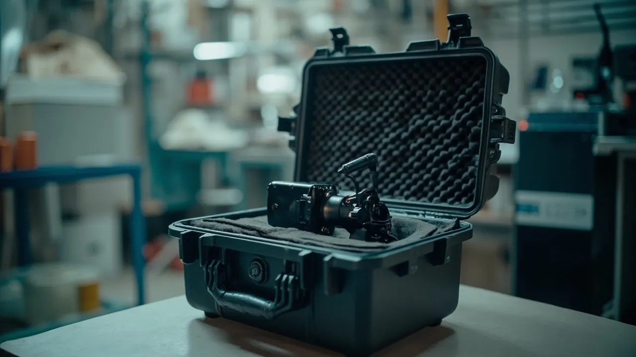
The core of protecting pumps, valves and fittings in transit is not surviving impact. It is preserving the mating surfaces. A pump impeller, a valve seat sealing face, a flange serrated water line: each is a functional surface machined to tolerances measured in microns to millimetres. Once such a surface is bumped, scored, dented or corroded, the consequence is not cosmetic. It is loss of dynamic balance, internal leakage past a valve seat, or seepage at a flanged joint. These problems may not even appear during factory testing. They surface in a concentrated way during pressure testing and commissioning on site. The pump and valve industry therefore follows a simple but strict rule: critical mating surfaces must not contact any rigid object during transport.
Pump, valve and fitting products carry two further characteristics. The first is cleanliness: foundry sand and machining swarf left inside a casting can enter the seal chamber and bearings in service and cause abrasive wear, and cleanliness requirements are stricter still for chemical, petrochemical and pharmaceutical duty. The second is that appearance is quality: when a customer inspects a pump or valve, appearance is the first item examined, and rust spots, dents or scores are frequently rejected outright even when function is intact, leading to returns and claims. This article is written for packaging and quality engineers at pump and valve manufacturers, foundries and forges, mechanical equipment suppliers and export trading firms. It works through protection by critical surface rather than by product. All figures are typical industry values or empirical ranges; the governing inputs are the drawing requirements, material standards and the customer's acceptance specification. JUNZHJIA supplies model-specific custom inserts, compartment systems, rust-prevention and sealing configurations, OEM and ODM programmes, and supporting test documentation for pump, valve and fitting cases.
Table of Contents
- 1. Why Pump and Valve Transport Is Fundamentally a Mating-Surface Problem
- 2. Impeller, Valve Body and Flange: Critical Surfaces and Failure Modes
- 3. Impeller Cases: Protecting Balanced Rotating Parts and Cast Blades
- 4. Valve Body and Bonnet Cases: Sealing Faces, Stuffing Box and Internal Cavity
- 5. Flanges and Fittings: Water Lines, Weld Bevels and Threads
- 6. Discs, Seats and Small Parts: The Value of Compartmentalisation
- 7. Component-to-Case Selection Matrix
- 8. Lining and Vibration-Isolation Materials Compared
- 9. Rust Prevention and Cleanliness Management: Appearance Is Quality
- 10. Sealing, Moisture Control and IP Ratings: IEC 60529 and GB/T 4208
- 11. Transport Test Basis and Standard Packing Workflow
- 12. Sea Export, Returnable Re-Use and OEM/ODM Customisation
- Frequently Asked Questions
- Conclusion and Further Reading
1. Why Pump and Valve Transport Is Fundamentally a Mating-Surface Problem
To understand packaging for pumps and valves, start with where the value sits. A large share of a centrifugal pump's cost concentrates in three places: the casting accuracy and dynamic balance of the impeller, the surface quality of the casing flow passages, and the machining accuracy of the mechanical seal and mating faces. A valve's cost is likewise concentrated in the soundness of the body casting, the sealing face accuracy of seat and disc, and the machined quality of the flange faces. All of these have one property in common: their value comes from geometric precision, and geometric precision is most vulnerable to local loading and hard contact.
Three governing principles follow from this.
First, critical surfaces must not contact rigid objects. An impeller must not rest directly on the case floor or touch other metal parts. A valve seat sealing face must not strike other valves or metal components. A flange serrated water line must not touch any hard object. This sounds obvious, yet it is the main source of site damage. Many factories simply pack into a carton with loose foam, the foam migrates, the component moves freely, and metal strikes metal.
Second, weight must be carried by dedicated load-bearing structures, not by critical surfaces. Large pump casings and valve bodies can weigh hundreds of kilograms. If a flange face or machined surface directly carries stacking load, even without visible impact the result is micro-plastic deformation that destroys flatness. The correct approach uses dedicated load blocks and a pallet plate to carry the weight, leaving critical surfaces either unsupported or very lightly constrained.
Third, cleanliness must be closed out before the case is closed. Once packed, foundry sand and swarf in internal cavities, threaded holes, oil galleries and seal chambers can no longer be verified effectively. For pumps and valves serving chemical, petrochemical, pharmaceutical and food duty, cleanliness is a quality attribute, so cleaning, drying and inspection must be completed before packing.
A common misconception treats a stiff case as the quality guarantee. For pump and valve products, case strength addresses external load only. What actually determines the arrival acceptance rate is insert location accuracy, isolation completeness and cleanliness control. A very stiff case with a misaligned insert can cause more damage than an ordinary case.
With these principles in mind, it becomes clear why pump and valve cases must be customised to the model rather than filled generically.
2. Impeller, Valve Body and Flange: Critical Surfaces and Failure Modes
| Component | Critical functional surface | Primary failure mode | Trigger | Priority countermeasure |
|---|---|---|---|---|
| --- | --- | --- | --- | --- |
| Centrifugal pump impeller | Blade profile, shroud and hub faces, dynamic balance | Blade compression, deformation causing imbalance | Lateral squeeze, hard contact, stacking | Dedicated support cavity plus surface-contact pad plus ban on stacking |
| Impeller | Shaft bore and keyway | Keyway edge collapse, bore scoring | Hard-object impact, unsupported loading | Bore protector plus keyway clearance |
| Pump casing or volute | Flow passage wall, flange face | Passage scoring, flange face denting | Residual sand in cavity, flange bearing load | Cavity capping plus flange cap plus load-bearing base |
| Valve body | Seat sealing face, flange water line | Face scoring causing internal leakage | Direct metal-to-metal contact, stacking | Sealing face cap plus end-face isolation |
| Bonnet and stuffing box | Stuffing bore wall, bolt holes | Bore scoring, bolt hole deformation | Hard contact, threaded hole loading | Port plugs plus compartmentalised placement |
| Flange | Serrated water line | Water line flattening causing joint seepage | Stacking, hard contact, strap compression | Full-face cap plus interlayer separator pad |
| Fitting (elbow, tee) | Weld bevel, thread, internal wall | Bevel damage, thread deformation | Unprotected stacking | Bevel ring plus thread protector |
| Disc and seat (separable pairs) | Precision conical or spherical sealing face | Face scoring | Mixed loose packing, free movement | Dedicated compartment plus soft lining |
| Fasteners and gaskets | Thread, sealing face | Loss through mixing, gasket damage | No compartments, free movement | Compartment box plus packing list label |
The nine modes share a common property: damage occurs on a surface and manifests in performance. Local blade compression does not change the external dimensions but alters dynamic balance. A flange water line dent is nearly invisible to the eye but seeps under pressure. Arrival inspection for these products must therefore treat critical surfaces as separate line items rather than checking overall appearance.
3. Impeller Cases: Protecting Balanced Rotating Parts and Cast Blades
The impeller is the pump's working component and the part in most need of careful handling.
Why impellers are vulnerable to compression. Centrifugal pump impellers are usually cast or welded structures, with blade thickness set by hydraulic design and typically in the range of a few millimetres. Blades behave as cantilevered thin-wall elements and deform plastically under lateral compression. Even a few tenths of a millimetre of deformation destroys dynamic balance. Because the impeller is a high-speed rotating part, imbalance generates centrifugal force in service, appearing as excessive vibration and noise and shortening bearing life. Critically, imbalance cannot be corrected on site; the impeller must return to the factory for balancing, which is costly and slow.
Design points.
- Dedicated support cavity: the impeller gets its own cavity and touches no rigid surface on any side. Support should act on the shroud face or hub, which are the stiffer regions, never on the blades.
- Surface-contact padding: contact faces should be soft, using low-rebound EVA, PU or felt facing, avoiding point contact and local stress concentration.
- No stacking: multiple impellers must never be stacked on each other. Locate each individually, upright or flat. Where stacking is unavoidable, use rigid separator plates and ensure weight transfers through the hub rather than the blades.
- Bore and keyway protection: shaft bores and keyways are mating surfaces and need protectors or plugs against impact and corrosion. Keyway edges collapse easily.
- Attitude control: avoid leaving an impeller in an attitude where blades carry gravity load for long periods. Large impellers should stand upright in the design attitude with a cradle supporting the shroud.
Material differences. Cast iron impellers are relatively brittle and chip on impact. Stainless steel impellers offer better toughness and corrosion resistance but their machined surfaces score easily. Duplex and nickel-alloy impellers are high value with strict surface integrity requirements. Insert hardness and contact method should differ by material: brittle materials emphasise impact resistance, ductile materials emphasise anti-scuff protection.
Double-suction and multistage impellers. Double-suction impellers are large and heavy and need cradles supporting both shrouds. Multistage pump impellers differ in size stage by stage, and mixed packing invites mutual impact, so strict compartmentalisation with stage labelling is essential to prevent site mis-assembly. Such multi-specification scenarios suit adjustable compartment systems; the zoning logic is described in removable divider system.
Traceability of balance condition. On arrival, record appearance and rotation condition, checking by hand for rubbing, and re-verify critical dimensions before assembly. Where the customer requires balance re-verification, record the initial value before packing to create a comparable baseline.
4. Valve Body and Bonnet Cases: Sealing Faces, Stuffing Box and Internal Cavity
The valve body is the main pressure-containing part, and its value concentrates in two places: the seat sealing face and the flange or weld connection face. The bonnet's stuffing box and bolt holes also need protection.
Seat sealing face. The seat face is what enables the valve to shut off flow, and both flatness and surface roughness are specified. Transit scoring causes internal leakage. If factory pressure testing has already been completed, repair means re-machining and lapping, which is expensive. The practice is to fit a dedicated cap, in plastic or soft material, over the sealing face, and to keep the face in a state where it touches nothing inside the case. For gate and globe valves with internal cavities, any machined internal surfaces must also be protected from foreign objects.
Flange water line. A flange water line, whether spiral or concentric serrated, seals by controlled plastic deformation. Once the serrations are crushed or flattened, sealing capability drops. Flanges are the part most often "casually stacked" in transit, because they conveniently serve as a bearing surface. A flange face must never be used as a load-bearing surface. Use full-face flange caps to protect the water line and carry weight through load blocks.
Stuffing box and bolt holes. The stuffing bore wall is finish-machined, and scoring degrades packing performance. Deformed bolt holes make assembly difficult. Fit port plugs, and place bonnets in their own compartments so they never contact bodies or other metal parts directly.
Internal cavity cleanliness. Foundry sand, core sand and machining swarf inside a casting are among the most common hidden defect sources in pump and valve products. Before packing, complete cavity cleaning and inspection, threaded hole blowing, and sealing face cleaning and wiping. Once clean, cap all openings immediately with plugs or protective covers to prevent re-contamination. For demanding industries such as chemical, petrochemical, pharmaceutical and food, record the cleanliness condition and the inspector in the packing record.
Body material and corrosion protection. Cast iron and carbon steel bodies rust readily in humid conditions, so apply anti-rust treatment such as a thin oil film or vapour-phase corrosion inhibitor with desiccant. Stainless bodies need isolation from carbon steel to prevent galvanic corrosion. Lined valves with rubber or fluoropolymer linings carry a vulnerable corrosion barrier that must be protected from point contact and over-tight strapping.
Valve open or closed position. Some valve types require a specific position during transport to protect the seat, for example avoiding a fully closed position that leaves the seat under sustained load. The correct state follows the product technical documentation and valve type, and should be written explicitly into the packing work instruction rather than left to operator judgement.

5. Flanges and Fittings: Water Lines, Weld Bevels and Threads
Flanges, elbows, tees and reducers are numerous, varied in size and relatively low in unit value, which makes them the parts most often stacked casually and the parts most likely to generate batch appearance rejections.
Protecting the flange water line. The water line is the sealing function of the flange, commonly concentric or spiral serrations. Crushing, flattening or scoring directly reduces sealing capability, and for high-pressure flanges the integrity of the water line matters even more. The core protective measure is full-face coverage: the cap should cover the entire sealing end face across the full inner to outer diameter range, not just the raised face or the boss. When flanges are stacked, place separator pads between layers so water lines never meet each other under load. Where strapping is necessary, use wide webbing with corner protectors, never cord tightened directly on a flange.
Weld bevel protection. The bevel on a butt-weld fitting is the datum for welding, and impact damage or deformation affects weld quality and fit-up accuracy. Fit bevel rings or plastic protective rings so the bevel carries no force. Large-diameter butt-weld flanges and fittings are usually shipped upright in dedicated cradles so the bevel end never rests on the ground.
Thread protection. Once a threaded fitting's thread is damaged, it is difficult to repair on site. Fit plastic thread protectors or caps and keep threads out of the load path.
Internal walls and coatings. Fittings for water, gas or chemical service may have internal coatings or linings that form the corrosion barrier and blister or delaminate under compression. Internal walls of such fittings must not take point loads, and residual liquid or moisture should be drained and dried before packing. Stainless fittings must be isolated from carbon steel to avoid galvanic corrosion and iron contamination.
Stacking and interlayer separation. Recommended practice is large diameters below, small diameters above; flange faces pointing up or outward so two water lines are never loaded against each other; separator pads between layers such as corrugated board, PE sheet or foam board; and a limited number of pieces per layer so the bottom layer is not over-loaded.
Specification and labelling discipline. The most frequent problem with fittings is specification confusion. Compartmentalise by specification, label by project number and size, and list details and quantities on the packing list. For multi-specification project kits, pack in layers and label each layer so site staff can count by layer. This kind of management requirement is delivered through the zoning and labelling methods described in custom foam insert design guide.
6. Discs, Seats and Small Parts: The Value of Compartmentalisation
Discs, seats, O-rings, packing, gaskets and bolts are the assembly essentials of a pump or valve, and also the parts most likely to be lost or damaged in transit.
Why small parts need compartments. If loose parts move freely inside a case, they strike and abrade each other under vibration, and they can work into the gaps around large components and score them. Loss is a more serious problem: one missing gasket or O-ring on site can stop an entire unit from being assembled, creating schedule delay. The value of compartmentalisation is not only protection but counting efficiency: each pocket carries a number, the packing list maps to the pockets, and unpacking becomes a direct check.
Protecting precision discs and seats. The conical face, spherical face and sealing groove of a valve disc are precision mating surfaces whose geometry determines the valve's leakage class. These parts need soft-lined, dedicated compartments touching no hard objects. Where surface roughness requirements are strict, the lining must be non-shedding and non-scuffing. Where a disc and seat are machined as a matched pair, pack them together in the same pocket to avoid mismatching on site.
Age control for seals. Rubber seals including O-rings and gaskets have storage life limits, and their performance changes with storage time and temperature. Label the production date or expiry date to avoid shelf-life problems. Seals should be protected from compression set and direct sunlight, and should not sit in prolonged contact with oils.
Fastener kit management. Bolts, nuts and washers should be compartmentalised by size and either packed with the component they serve or clearly labelled with the owning component. Mixed packing is the main cause of site mis-assembly. Where torque requirements apply, note specification and quantity on the packing list for verification.
Accessories and tooling. Special tools, spares, test reports and technical documents should be consolidated in a dedicated document pouch or tool pocket fixed to the inside of the lid so they cannot shift in transit.
7. Component-to-Case Selection Matrix
| Component | Typical weight | Insert scheme | Case format | Sealing guidance | Critical constraints |
|---|---|---|---|---|---|
| --- | --- | --- | --- | --- | --- |
| Large centrifugal pump impeller | 20-200 kg | Cradle plus surface-contact pad plus dedicated cavity | Heavy frame or pallet case | IP65 | No blade loading, no stacking |
| Small and medium impeller | 3-30 kg | Compartment plus soft lining | Standard case with dividers | IP65 | Keyway and bore protection |
| Pump casing or volute | 30-300 kg | Cavity cap plus flange cap plus load-bearing base | Heavy frame case | IP65 | Flange face not load bearing |
| Valve body (DN50 to DN300) | 20-400 kg | Sealing face cap plus end-face isolation plus load-bearing base | Heavy or medium case | IP65 | Seat unloaded, correct open-close state |
| Bonnet or stuffing box part | 5-60 kg | Port plug plus compartment | Standard case with dividers | IP65 | Stuffing bore wall protection |
| Flange and butt-weld fitting | 2-80 kg | Full-face cap plus bevel ring plus interlayer separator | Standard case with layers | IP65/IP67 | Water line touches no hard object |
| Disc and seat (matched pair) | Under 10 kg | Dedicated compartment plus soft lining | Carrying or compartmented case | IP67 | Zero scoring on conical or spherical face |
| Seals and fasteners | Under 10 kg | Compartment box plus packing list label | Internal compartments | IP65 | Age labelling, no mixing |
| Actuator or control unit | 5-40 kg | Low-rebound full floating wrap | Medium case | IP65 plus desiccant | Vibration, moisture |
Three empirical rules apply. First, any component with a machined sealing face must never use that face as a support surface. Second, any component above 60 kg requires a case with mechanical lifting or forklift capability. Third, any multi-specification shipment must deliver a three-way match between compartments, labels and the packing list, otherwise site counting cost rises sharply.
8. Lining and Vibration-Isolation Materials Compared
| Material or structure | Typical density | Load behaviour | Surface behaviour | Best-fit components | Cautions |
|---|---|---|---|---|---|
| --- | --- | --- | --- | --- | --- |
| EVA (medium to high density) | 60-120 kg/m3 | Good load bearing, low compression set | Soft, non-shedding | Valve bodies, flanges, impeller contact faces | Slightly soft when hot |
| Low-rebound EVA | 40-90 kg/m3 | Good damping | Soft | Actuators, control units | Load bearing needs a structural part |
| PU foam | 25-60 kg/m3 | Medium-low load bearing | Soft | Small parts, compartment liners | May collapse under long compression |
| XPE/IXPE | 30-80 kg/m3 | Low load bearing | Flat and even | Flange interlayer separators | Not a load bearer |
| Structural foam (cross-linked PVC/PE) | 60-300 kg/m3 | High load bearing, low deformation | Machinable, relatively hard | Load blocks, cradles | Contact faces need a soft facing |
| Felt or non-woven facing | Not applicable | No load bearing | Extremely soft, anti-scuff | Precision sealing faces, precision discs | Needs moisture and mould protection |
| Corrugated or honeycomb separator | Not applicable | Medium | Flat and even | Flange interlayers, fitting layers | Needs moisture protection |
Selection logic. The core principle for pump and valve linings is division of labour: structural foam or high-density EVA carries load; soft facing handles contact; low-rebound material isolates vibration; flat separators provide isolation. Using a single material to perform all four roles usually sacrifices one of them. For example, hard structural foam in direct contact with a valve seat sealing face will score it, so a soft facing is mandatory; conversely, soft foam carrying the weight of a valve body collapses under long stacking, so a load block is mandatory.
Surface compatibility. Pump and valve work frequently encounters incompatibility between lining material and product surface. The typical symptom is migratable constituents transferring to the metal surface under high temperature and humidity, leaving hard-to-remove stains or affecting adhesion of subsequent coatings. For products scheduled for painting, plating or surface treatment, confirm compatibility between the lining material and the downstream process. Material comparisons are set out in protective case foam material comparison and EVA insert customisation process.
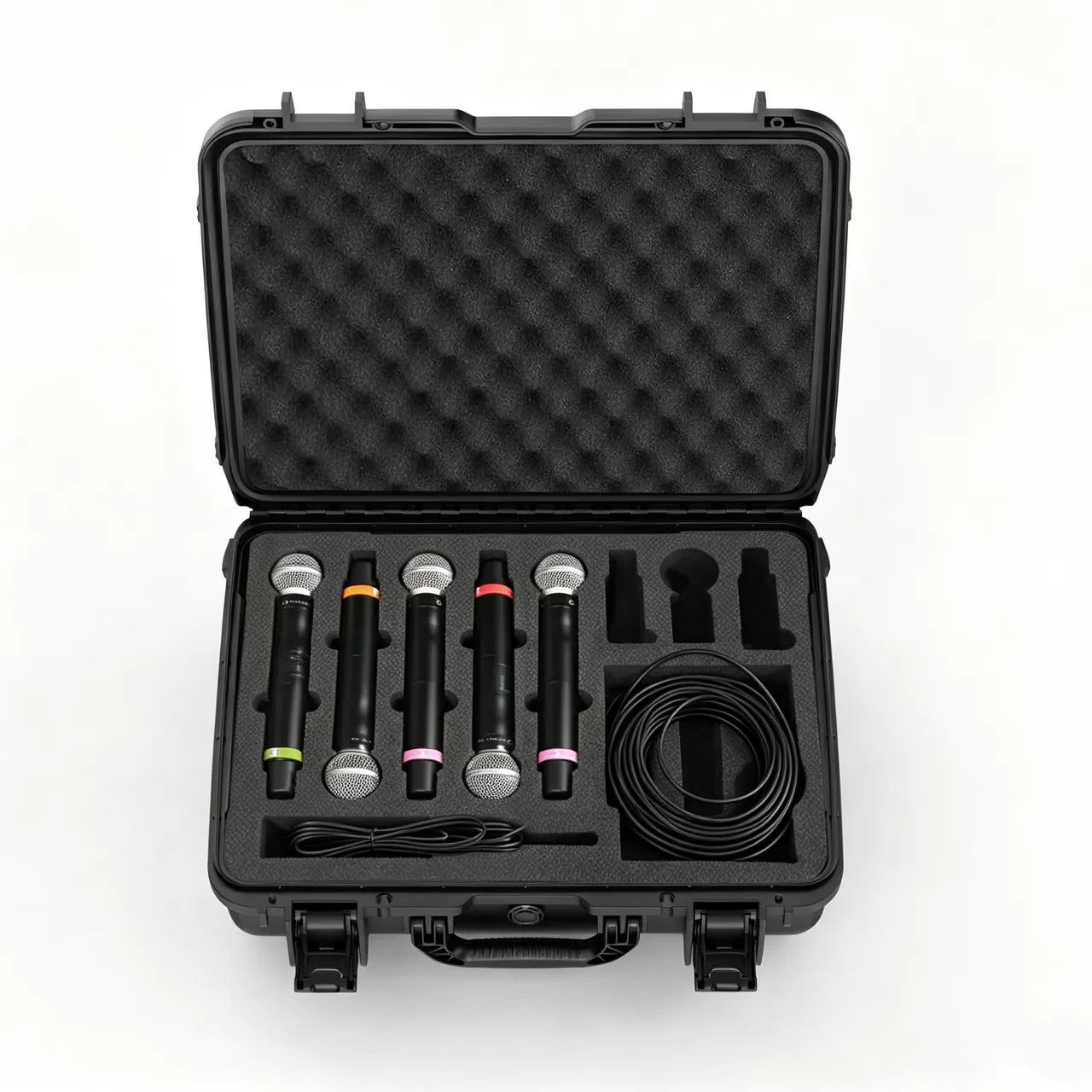
9. Rust Prevention and Cleanliness Management: Appearance Is Quality
In the pump and valve industry, appearance inspection is usually the customer's first acceptance gate. A single rust spot can trigger rejection of a whole batch even when every functional indicator passes. Rust prevention and cleanliness management are therefore not additional requirements; they are core elements of the packaging scheme.
Three conditions required for corrosion. Metal corrosion requires moisture or high humidity, oxygen, and a conductive electrolyte such as chloride or salt. The essence of packaging protection is cutting the moisture path. Practical measures include controlling the humidity of the packing environment, using desiccant, applying vapour-phase corrosion inhibitor materials, applying short-term rust-preventive treatment to machined surfaces, and using barrier film to exclude external moisture.
Protection priorities by material.
- Cast iron: surface graphite morphology and roughness retain moisture, so rust-preventive oil or VCI treatment is the priority.
- Carbon steel: both coatings and machined surfaces need protection, and a score becomes a corrosion initiation point.
- Stainless steel: the priority is not rust prevention but preventing passive layer damage and iron contamination, so direct contact with carbon steel is prohibited.
- Non-ferrous metals (copper alloys, aluminium alloys): watch for galvanic corrosion from contact with dissimilar metals, and for corrosion from specific media such as ammonia and sulphides.
- Plated parts (zinc, nickel): once the plating is scored it no longer protects, so contact faces need soft padding.
Closed-loop cleanliness steps. Write cleanliness control as a work instruction: clean, meaning remove swarf, oil and foundry sand; dry, meaning blow out threaded holes and internal cavities with compressed air; inspect, using visual checks and a white cloth wipe test; cap, meaning protect openings with covers; and record, noting the inspector and the time. This must be closed loop because once the case is closed it can no longer be verified, and once contamination enters a system the traceability cost is very high.
Aligning with customer standards. Cleanliness and surface quality requirements vary widely by industry. General industrial pumps and valves focus on appearance and function. Chemical and petrochemical duty demands higher cleanliness and material certification. Pharmaceutical and food duty brings sanitary requirements and material compliance documentation. The specific cleanliness class, acceptance criteria and applicable standards are governed by the customer's technical agreement and the product standard; this article draws no compliance conclusion. Clarify at the enquiry and contract stage which cleanliness requirements apply, which surface defects are permissible and to what degree, and whether material certificates and test reports are required.
10. Sealing, Moisture Control and IP Ratings: IEC 60529 and GB/T 4208
Rust prevention for pump and valve products depends heavily on the case's moisture resistance, which is a direct function of sealing class.
What the IP code means. The IP code defined in IEC 60529 uses two digits, the first for solids protection from 0 to 6 and the second for water protection from 0 to 9K. The equivalent Chinese standard is GB/T 4208. Typical configurations for pump and valve cases are as follows.
- IP54: limited dust protection and splash resistance, for short domestic routes with covered transport and short-term storage.
- IP65: dust tight and water-jet resistant, for most components on domestic and near-sea routes.
- IP67: dust tight with short-term immersion tolerance, typically 1 m for 30 minutes, for sea freight, open-air storage and high-humidity, high-salt-fog regions.
- IP68: continuous immersion, needed only in extreme scenarios.
Trade-offs between levels are examined in IP67 protective case design essentials.
Reminder one: an IP rating verifies that external water does not enter. It does not guarantee the absence of internal condensation. A sealed case cannot easily expel internal moisture across a day-night temperature cycle, which can actually be harmful to rust-protected metal parts, since condensation disrupts the oil film. Sealing, desiccant and a humidity indicator card should be used together, with a pressure equalisation valve on routes with large temperature swings.
Reminder two: rust prevention is not only about keeping external water out; it is also about controlling internal moisture sources. Timber packaging, paper fillers and undried cleaning residue are all internal moisture sources. Confirm the component is fully dry before packing and avoid the most common error of all, which is sealing a damp part inside a sealed case.
Seals and latches. Gasket materials are commonly silicone, EPDM and foamed TPE, with the cross-section matched to the case groove. Latch count must match lid stiffness, with three or more latches advisable when lid length exceeds 800 mm. Seals are wear items and need a spare parts list with replacement criteria, as detailed in hinge, latch and seal selection and protective case service life.
Desiccant sizing logic. Desiccant quantity should be calculated from free internal volume, the hygroscopicity of packaging materials, transit duration and target humidity. Where a pump or valve case contains large amounts of timber or paper, their moisture uptake consumes desiccant capacity significantly and must be included. A 30 to 45 day sea crossing requires clearly more than a short domestic route.
11. Transport Test Basis and Standard Packing Workflow
Test basis. Verification of pump and valve cases typically references four families of standards. These are a different layer of requirement from the product's own performance standards, such as pump hydraulic acceptance test standards (for example ISO 9906) or valve pressure test standards (for example ISO 5208), and the two should not be confused.
The ISTA series. Procedures from the International Safe Transit Association are graded by package format and weight. Medium and large components commonly reference ISTA 3E for unitised loads or ISTA 3B for less-than-truckload distribution, with ISTA 2A or 2B for single packages. The value lies in sequencing: conditioning, then shock or drop, then vibration, then re-inspection. See ISTA transport testing procedures.
The GB/T 4857 series. These Chinese standards cover basic test methods for transport packages including vibration, shock, stacking and drop, and are widely referenced in domestic tenders and acceptance documents. See GB/T 4857 transport packaging.
ASTM D4169. This standard assigns test intensity by distribution cycle and is widely used for packaging validation targeting the North American market. See ASTM D4169 distribution cycle testing.
MIL-STD-810H. Its environmental test methods covering vibration, shock, temperature and humidity, and salt fog are frequently cited. This must be stated clearly: MIL-STD-810H is used here as a source of environmental test methodology and does not imply that any product has obtained military certification. See MIL-STD-810H environmental test compliance.
| Test type | Common standard | Example parameters | Relevance to pump and valve parts |
|---|---|---|---|
| --- | --- | --- | --- |
| Random vibration | ISTA 3E, ASTM D4169 | Power spectral density, duration | Verifies insert location and component restraint |
| Shock and drop | GB/T 4857, ISTA | Drop height, peak acceleration | Verifies sealing face and flange water line protection |
| Stacking | GB/T 4857.3 | Load, duration, temperature and humidity | Verifies case compression strength and deformation resistance |
| Temperature and humidity cycling | MIL-STD-810H Method 507 | Temperature range, cycle count | Verifies rust prevention scheme and condensation risk |
| Salt fog | ISO 9227, ASTM B117 | Concentration, duration | Verifies plating, coating and stainless steel |
| Water ingress | IEC 60529, GB/T 4208 | IP class, test duration | Verifies case sealing effectiveness |
| Flammability (material) | UL94 | Class quoted against material and thickness | Verifies case plastic parts and insert foam |
Where UL94 applies. UL94 is a flammability classification standard for plastic materials, used to rate case plastic parts, insert foams and gasket materials themselves. It is not a fire certification for a machine or a packaging system. A UL94 class must always be quoted with the material and thickness, because the same material can achieve different classes at different thicknesses. Where a customer specifies flame retardancy, confirm the material and thickness combination at the enquiry stage.
Arrival functional checks. Transport verification for pump and valve parts should be judged on function and critical surfaces: whether flange water lines show impressions, whether seat faces are scored, whether the impeller rubs, whether rotation is free, whether internal cavities are clean, and whether rust spots have appeared. Where the customer requires valve pressure testing or pump performance testing, repeat the product-standard test after transport testing and use functional criteria to confirm packaging effectiveness.
Standard packing workflow (SOP).
- Verify and clean. Confirm specification, quantity and kit relationships. Complete cleaning, blow-drying and inspection. Cap threaded holes and internal cavities.
- Pre-treat for protection. Fit sealing face caps, full-face flange caps, bevel rings and thread protectors. Apply short-term rust-preventive treatment to machined surfaces.
- Pre-fit the lining. Place load blocks, cradles, compartments and soft facings, confirming no debris and no misalignment. Trial-fit and record the first article.
- Position the component. Lower into the design attitude without dragging or dropping. Confirm critical surfaces touch no rigid object and that weight transfers through the load blocks.
- Restrain and locate. Install the top limit. Where multiple items share a case, compartmentalise strictly and never stack. Confirm no perceptible movement by hand, with an empirical limit of 2 mm displacement.
- Small parts and documents. Place discs, seats, seals and fasteners in their labelled pockets. Put documents and test reports in a pouch and secure it.
- Seal and dry. Add desiccant sized from internal volume and transit duration plus a humidity indicator card. Check the gasket. Close the latches and confirm uniform loading around the perimeter.
- Mark and record. Apply rain-protection, this-way-up, centre-of-gravity, lifting and fragile-area labels. Photograph the packed case including critical surface protection and archive the images.
Field experience: disputes over pump and valve parts usually centre on critical surface damage. Packing photographs should therefore include three categories of image, namely the protection caps before and after fitting, close-ups of critical surfaces, and the completed compartment layout. Comparing these on arrival makes responsibility determination far clearer.
12. Sea Export, Returnable Re-Use and OEM/ODM Customisation
Six key variables in sea export. First, transit lasts 30 to 45 days, so desiccant quantity must be calculated from volume and duration, including the hygroscopicity of paper and timber materials. Second, the day-night temperature swing inside a container drives condensation, so a pressure equalisation valve is advisable and the component must be confirmed dry before packing. Third, salt fog exposure requires suitable corrosion protection on plating, coatings and fasteners, with isolation between stainless and carbon steel being especially critical. Fourth, stacking layers at sea are usually higher, so compressive strength must be calculated for the worst-case stack and flanges and valve bodies must never serve as load-bearing surfaces. Fifth, export wooden packaging must meet ISPM 15 fumigation or heat treatment requirements; a plastic case avoids this issue but must still satisfy the destination market's environmental and recyclability requirements, and where timber liners are used the corrosion risk to metal parts must be assessed. Sixth, sea freight usually connects to local truck delivery, and that last short leg often produces the most severe handling shock.
Returnable re-use criteria. Pump and valve manufacturers often use returnable cases between internal process steps and customers. Before re-use, check five items: shell cracks or deformation, especially floor and corners; gasket hardening, cracking or permanent set; latch and hinge ability to close and carry load; lining collapse, fracture, facing delamination or missing compartments; and castor and handle wear. Replace any failed item before reuse, with criteria detailed in protective case service life. Two additional warnings apply to this industry. Returnable case linings accumulate metal swarf and oil over time, so they must be cleaned or replaced before carrying precision discs, seats or painted parts, otherwise they become a new contamination source. And sealed cases stored for long periods with moisture inside can develop mould or odour, which should also be part of the inspection.
OEM/ODM points. Pump, valve and fitting cases are an extremely fragmented category with widely varying batch sizes. The procurement strategy should be built around standardised cases, customised linings and modular compartments: cover most specifications with three to five standard case sizes; customise linings by specification while keeping the cavity standard so linings remain interchangeable; and design compartment modules along specification families so that one case serves many uses. This amortises tooling and fixture cost across many specifications. See custom case mould cost analysis.
Five dimensions for supplier evaluation. Engineering capability, meaning the ability to issue an insert and compartment proposal from drawings or 3D data and to run a first-article trial fit. Materials and process, covering foam density batch consistency, the abrasion resistance and non-shedding behaviour of facing materials, and gasket cross-section and hardness. Test capability, covering vibration, drop, stacking, water ingress and salt fog records. Delivery and capacity, including peak-season flexibility and lead-time reliability. Quality system, including inspection rules and non-conforming material handling, using the sampling practice described in custom case acceptance and AQL.
Enquiry checklist. A practical enquiry should include component model and specification, material and surface treatment requirements, weight and centre of gravity, a list of critical functional surfaces with permissible defect criteria, cleanliness requirements, transport mode and route, number of re-use cycles, storage environment, target IP rating, test requirements, marking and documentation requirements, annual volume and delivery cadence. General guidance on evaluating factories is available in how to choose a protective case OEM factory.
JUNZHJIA normally works in the following sequence for pump, valve and fitting cases: accept drawings, 3D data or a physical impression, issue a compartmented insert proposal with critical surface protection recommendations, confirm the first article by trial fitting, then move to volume production with batch inspection and supporting test documentation. For customers shipping multiple specifications, compartment module archives are maintained by specification family so configurations can be reused and combined quickly.
Frequently Asked Questions
Q: Why does pump and valve transport focus on critical functional surfaces rather than overall strength?
A: Because both the value and the consequences of failure concentrate on those surfaces. Much of a pump's cost lies in the casting accuracy and dynamic balance of the impeller and the surface quality of the casing flow passages. A valve's cost concentrates in seat sealing face accuracy and the flange water line. What these surfaces share is that a dimensional deviation of a few tenths of a millimetre, or even a few microns, has a decisive effect on performance. Local blade compression destroys dynamic balance. A flange water line impression seeps under pressure. Seat scoring causes internal leakage. And the trigger for these outcomes is usually not a broken case but a component that moved inside the case and struck other metal parts. The protection focus must therefore shift from case strength to critical surface isolation: let dedicated load-bearing structures carry the weight, keep critical surfaces touching no rigid object, and prevent the component from moving inside the case. This is precisely why pump and valve cases must be customised to the model rather than filled generically.
Q: An impeller shows balance deviation after transit. What are the common causes?
A: The leading cause is lateral compression of the blades producing local plastic deformation, followed by incorrect support. Four typical scenarios apply. First, the impeller contacts other metal parts or the case wall directly, and transport vibration causes repeated impact that compresses the blades locally. Second, soft foam carries the impeller's weight and collapses under prolonged stacking, allowing the impeller to sink and contact the floor or another part. Third, multiple impellers are stacked on each other and the load transfers through the blades, deforming them. Fourth, support points fall on the blades rather than on the stiffer shroud or hub. Balance deviation is effectively unrepairable on site and requires a return to the factory for balancing, so prevention is essential. Recommended measures are a dedicated support cavity for the impeller, support acting on the shroud face, soft surface-contact padding at all contact points, a ban on stacking with individual compartments for every piece, protectors on bore and keyway, and large impellers standing upright in the design attitude with a cradle supporting the shroud.
Q: Why does a crushed flange water line cause leakage, and what special protection requirements apply?
A: Flange sealing works through local plastic deformation of the serrations under bolt preload, creating multiple line contacts. The geometric integrity of the water line therefore directly determines sealing capability: crushing, flattening or scoring reduces the number of effective sealing lines, and leakage appears under pressure and temperature cycling. Three special requirements follow. First, the cap must cover the full end face rather than just the raised face or boss, because the water line usually spans the entire ring from inner to outer diameter, so a partial cap leaves exposed zones. Second, a flange face must never be used as a load-bearing surface. Flanges are often casually stacked because they conveniently act as a natural support surface, which is the classic error; weight should be carried by load blocks and cradles, leaving the flange face unloaded. Third, interlayer separator pads are required when stacking so two water lines never face each other under load. Where strapping is necessary, use wide webbing with corner protectors and never tighten cord directly on a flange.
Q: Why must precision small parts such as discs and seats be compartmentalised?
A: Compartmentalisation delivers value in three dimensions at once: protection, loss prevention and efficiency. On protection, the conical face, spherical face and sealing groove of a valve disc are precision mating surfaces whose geometry determines the leakage class, and loose packing causes mutual impact and abrasion under vibration and possible crushing by larger components. On loss prevention, small parts such as O-rings, gaskets and bolts easily work into gaps around large components or escape through case seams, and a single missing part on site can prevent an entire unit from being assembled, creating downtime. On efficiency, each pocket carries a number that maps to the packing list, so unpacking becomes a direct count and specification check that takes far less time. Where a disc and seat are machined as a matched pair, pack them together in the same pocket to avoid mismatching on site. Seals also need age control, since rubber parts have storage life limits, so label the production or expiry date to avoid performance loss from long storage. These management actions cost very little and significantly reduce site problems.
Q: For pump and valve rust prevention, is desiccant alone enough?
A: No. Rust prevention is a system, of which desiccant is only one element. Corrosion requires moisture, oxygen and an electrolyte simultaneously, and the essence of packaging protection is cutting the moisture path. Moisture can enter from outside or originate inside. At least four measures therefore work together. First, confirm the component is fully dry before packing, paying particular attention to cleaning residue, pooled liquid in cavities and threaded holes, which are the most frequently overlooked internal moisture sources. Second, apply short-term rust-preventive treatment to machined surfaces using oil films or vapour-phase corrosion inhibitors to create a direct barrier. Third, control internal humidity with desiccant sized from volume and duration plus a humidity indicator card. Fourth, use barrier film to exclude external moisture and choose an IP rating matched to the environment. Material differences also matter: cast iron and carbon steel need focused rust protection, stainless steel needs protection of the passive layer and from iron contamination, and plated parts lose protection the moment the plating is scored. For high-value or long sea crossings, specify the rust prevention scheme and the arrival inspection method in the contract.
Q: When shipping a mix of pump and valve specifications, how do we avoid site mis-assembly and missing parts?
A: The core is a three-way match between compartments, labels and the packing list, combined with making mixed shipments layered and controllable. Five practices apply. First, design compartment modules by specification so that each specification only occupies its own pockets and never mixes with others. Second, number every pocket, apply matching number labels to the parts or their packaging, and list specifications and quantities by number on the packing list. Third, place matched sets such as disc and seat or bolt and gasket in the same pocket or layer as the parent component so kits never separate across cases. Fourth, pack multi-specification shipments in layers and label each layer on completion with layer number, specification and quantity, so site staff can count by layer without unpacking everything. Fifth, for specifications that look alike and are easily confused, such as flanges of the same diameter but different pressure classes, add a prominent distinguishing mark to the label and list them side by side on the packing list as a reminder. These practices are delivered through custom compartment inserts, and the incremental cost is modest relative to the effect on site efficiency and error rates.
Q: Should pump and valve parts ship in plastic cases or wooden crates?
A: The choice depends on product value, surface requirements, re-use demand and transport route, not on unit price comparison alone. Wooden crates offer low initial cost, dimensional flexibility and the ability to carry very large or heavy items, suiting one-way export and oversized components. Their drawbacks are nail heads and splinters on inner surfaces, which are a direct risk to sealing faces and stainless parts; moisture uptake that turns the crate into a humidity reservoir; ISPM 15 fumigation or heat treatment requirements for export; and poor suitability for repeated handling. Plastic cases offer smooth non-shedding inner surfaces, controllable sealing and moisture protection, replaceable seals, and suitability for repeated use and precision parts. Their drawbacks are higher tooling cost and size limitations for very large items. A common compromise in practice is plastic cases with compartmented inserts for small and medium precision parts such as impellers, discs, seats and flanges, and wooden crates with sealed liners and isolating layers for oversized items such as large pump casings and large-diameter valve bodies. Whichever is chosen, the decisive factor is the insert scheme and critical surface protection, not the case material itself.
Q: How do I judge whether a pump or valve transport case can continue in service?
A: Establish explicit re-use criteria rather than relying on judgement. Check five items. First, the shell for cracks, deformation and through-damage, focusing on the floor and corners. Second, the gasket for hardening, cracking, debonding or permanent set, assessed by feel and cross-section recovery. Third, latches and hinges for reliable closing and load carrying without looseness, corrosion or binding. Fourth, the lining for collapse, fracture, facing delamination, dusting or missing compartments, since collapse directly defeats location on the next trip and delaminated facing debris contaminates precision parts. Fifth, castor and handle wear. Replace any failed item before reuse. Two additional points apply to this industry. Linings in long-serving returnable cases accumulate metal swarf and oil, so they must be cleaned or replaced before carrying precision discs, seats or painted parts. Sealed cases stored for long periods with moisture inside can develop mould or odour, which should also be inspected. Maintaining a log of case number, cycle count, previous contents and inspection records is the lowest-cost and most direct management method available.
Conclusion and Further Reading
Protecting pumps, valves and fittings in transit is fundamentally a critical-surface management problem. The dynamic balance of an impeller, the sealing face of a valve seat and the water line of a flange are functional surfaces machined to micron or sub-millimetre accuracy. They determine how the product performs under pressure test and in service, and they determine the customer's first impression at acceptance. Their common vulnerabilities are local loading, hard contact, moisture and contamination, while overall impact is not necessarily the main threat. An effective packaging scheme is therefore not the thickest case available, but a design that assigns load bearing, isolation, contact and rust prevention each to an appropriate structure.
The implementation path compresses into four steps: list the critical functional surfaces first, then define the load path and isolation scheme, then resolve mixed packing and counting with compartments and labels, and finally close the loop with transport testing and arrival functional checks. Doing so significantly reduces the probability of a case that looks perfect on arrival while the joint seeps during pressure test. Where a compartmented insert proposal with critical surface protection recommendations is needed for a specific model, provide drawings, 3D data or a physical impression to JUNZHJIA, which will issue drawings and arrange first-article trial fitting.
Further Reading