

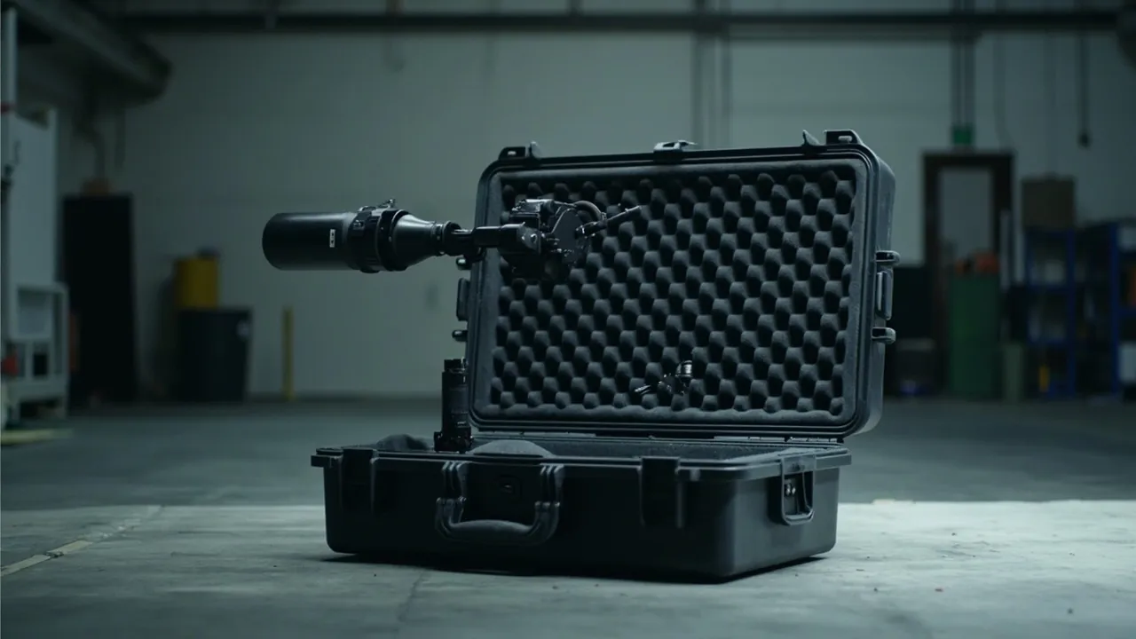
Protecting conveyor rollers and drive components in transit is the most commonly downgraded step in the logistics equipment supply chain. Many manufacturers treat rollers like plain steel tubes, gearboxes like ordinary castings, and motorized drums like ordinary motors. The price is paid on site: roller face dents cause conveying runout, shaft end deformation causes tracking deviation, bearing contamination causes early-stage noise, and shock to a motorized drum causes insulation or encoder failure. The conclusion is clear: rollers are precision bodies of revolution and drive components are precision electromechanical parts. Both require a dedicated parts case with separated cavity location, damage-resistant inserts, vibration-damped support, and controlled sealing - not loose bundling or crates stuffed with filler.
The distinguishing feature of a conveyor roller is its contact geometry. A roller is a slender body of revolution, and its face accuracy - roundness, straightness, surface roughness - directly governs conveying smoothness. Contact between a cylindrical surface and a flat surface is essentially line contact with high stress, and the roller rolls very easily, so laying rollers on plain foam cannot constrain them at all. At the same time, powered rollers and motorized drums integrate a motor, a reduction mechanism, and sensors inside the roller body, making them sensitive to shock acceleration and ESD. On the drive side, gearboxes, sprockets, tensioners, and frame side plates require shaft extension protection, tooth flank protection, spring protection, and straightness protection respectively. This article is written for conveyor manufacturers, specialist roller factories, logistics system integrators, and project buyers. It sets out graded protection schemes for rollers and drive components, insert and vibration isolation design, standard validation methods, and on-site acceptance rules, and it explains the engineering capability behind custom inserts and OEM/ODM supply.
Table of Contents
- 1. Why Conveyor Rollers Need a Dedicated Damage-Resistant Parts Case
- 2. Roller Types and Drive Component List
- 3. Failure Modes: Roller Face Damage, Shaft End Deformation, Bearing Contamination and Coating Delamination
- 4. Size and Weight Boundaries: Packing by Roller Diameter and Length
- 5. Case Structure and Material Selection
- 6. Three Insert Options: Vertical Slots, Horizontal Slots and Shaft-End Suspension
- 7. Drive Component Protection: Gearboxes, Sprockets and Tensioners
- 8. Motorized Drums and Servo Drives: Electrical Protection and Vibration Isolation
- 9. Sealing and Ingress Protection: An IEC 60529 and GB/T 4208 View
- 10. Rust Prevention and Cleanliness: The Hidden Risk at Shaft Ends and Bearings
- 11. Transport Vibration and Shock Validation: GB/T 4857.23 and ISTA
- 12. Stacking, Lifting and Heavy-Load Handling Awareness
- 13. Labelling, Traceability and Site Delivery Management
- 14. OEM/ODM Customization, Acceptance and Maintenance
- Frequently Asked Questions
- Conclusion & Related Reading
1. Why Conveyor Rollers Need a Dedicated Damage-Resistant Parts Case
A roller is the classic item that looks like a steel tube but is in fact a precision part. Its value is not in the material but in the geometric accuracy of the roller face and the fit accuracy of the shaft ends. Once either is lost, on-site remedies are extremely limited.
Roller face accuracy governs conveying smoothness. Roundness and straightness deviations convert into periodic runout during rotation. A slight roundness deviation may go unnoticed at low conveying speeds, but on high-speed sorters or high-takt production lines it amplifies into obvious vibration and noise and accelerates bearing and face wear.
Shaft end fit governs tracking. The fit between roller shaft ends and frame side plates or bearing housings fixes the roller's installed position. Once a shaft end is struck and deformed, assembly runs eccentric and inclined, and conveyed items drift to one side.
Bearings are the hidden weak point. Bearings are precision components, and once metal chips, grit, or foam debris enter the raceway, the failure surfaces only weeks or months after commissioning as noise and temperature rise. Root-cause tracing is difficult and the problem is often misdiagnosed as a quality defect.
Rubber coating cannot be repaired. Coated rollers increase friction or protect conveyed product surfaces, but once the coating is scored, delaminated, or permanently dented, the roller must be reworked or replaced.
Key reminder: most roller damage is cheap to prevent and expensive to reverse. The on-site cost of a single roller face score - disassembly, rework, line stoppage - far exceeds the packaging investment for the whole batch.
For specialist roller factories and conveyor manufacturers, the parts case also serves as standardised tooling. Building a standard case series by roller diameter and length significantly reduces storage and circulation cost. Reuse assessment methods are described in protective case service life and reuse years.
2. Roller Types and Drive Component List
Protection priorities differ markedly between roller types, so grade them before packing.
| Type / component | Typical material / structure | Critical sensitivity | Recommended protection |
|---|---|---|---|
| --- | --- | --- | --- |
| Gravity roller | Galvanized carbon steel or stainless | Face roundness, shaft ends | Vertical slots plus shaft-end sleeves |
| Powered roller | Body with internal bearing housing and sprocket or pulley | Face, sprocket teeth, shaft ends | Divider slots plus gear sleeves |
| Motorized drum | Motor and reduction gear inside the body | Electrical insulation, encoder, sealing | Isolated damped cavity, moisture barrier, ESD |
| Tapered roller | Cone body with bearings | Cone accuracy, shaft ends | Conformal slots plus end sleeves |
| Coated roller | Core with rubber, PU, or silicone coating | Coating integrity, roundness | Shaft-end suspension plus dust film |
| Sprocket and chain | Alloy steel | Tooth flanks, links | Separate cavities plus anti-rust paper |
| Gearbox | Cast iron or aluminium | Shaft extension, flange register, oil seal | Shaft sleeve plus flange cover |
| Drive motor | Cast aluminium or steel housing | Shaft extension, terminal cavity | Moisture barrier bag plus plug |
| Servo motor and encoder | Precision electromechanical | Shock acceleration, ESD | Isolated damped cavity plus ESD bag |
| Tensioner | Spring with screw or slider | Spring set, threads | Pre-compressed restraint plus thread sleeves |
| Frame side plate and guard | Folded sheet or extrusion | Flatness, mounting holes | Upright cavities plus edge protectors |
| Photoelectric switch and sensor | Electronic components | Lens face, cabling, ESD | Small-part box plus ESD packaging |
| Bearing housing and bearing | Cast iron or bearing steel | Fit surfaces, rolling elements | Isolated cavity plus dust cap |
Two threads stand out. Roller faces and shaft ends form the physical protection axis, while motorized drums, servo motors, and encoders form the electrical and vibration isolation axis. Small parts and fasteners add a third, loss-prevention thread.
3. Failure Modes: Roller Face Damage, Shaft End Deformation, Bearing Contamination and Coating Delamination
Roller face damage and ovalisation. Thin-walled rollers have low radial compression resistance. Stacking pressure or impact against a hard object produces face dents and, in severe cases, an oval cross-section. Each rotation then produces one impact, generating periodic vibration and noise.
Shaft end deformation and fit failure. Shaft ends are the mounting fit surfaces, usually turned on a lathe. After impact they show burrs, bending, or dimensional deviation, and assembly runs eccentric and inclined.
Bearing contamination and early failure. Metal chips, grit, and foam debris accelerate wear once inside the raceway, surfacing weeks after commissioning as noise, temperature rise, and vibration.
Coating damage. Coatings have low hardness and poor scoring resistance, so contact with hard objects or compression creates permanent dents. The bond interface between coating and core can delaminate under shear shock.
Sprocket tooth and chain damage. Struck tooth flanks create meshing impact and noise; deformed chain links disturb transmission synchronisation.
Electrical damage to motorized drums and servo parts. Shock above the acceleration limit can damage internal motor bearings, crack an encoder code disc, or loosen wiring. ESD can damage control circuits.
Permanent spring set. If a tensioner spring is held under compression or receives shock in transit, it can take a permanent set, leaving tension insufficient.
Practical judgement: transit damage to rollers and drive components has a delayed-onset character. The item looks normal at assembly, and noise and runout appear only after commissioning, when both liability allocation and troubleshooting cost are very high. Packaging must therefore be designed on a zero-damage rather than a looks-fine basis.
4. Size and Weight Boundaries: Packing by Roller Diameter and Length
Small diameter rollers (20-50 mm). Common on light-duty conveying and sorting lines, these have low rigidity and poor bending resistance. Use vertical divider slots or densely supported horizontal packing, and never leave long spans unsupported.
Medium diameter rollers (50-89 mm). The workhorse of general conveying lines. Horizontal half-round slots or layered slot schemes work well.
Large diameter rollers (89-200 mm and above). Heavy with high inertia, they require careful attention to support count, case load capacity, and lifting method.
Very long rollers (over 2,000 mm). Common on wide-belt conveying, these have lower rigidity still and demand multi-point support with controlled spacing.
| Diameter band | Typical length | Mass per piece (empirical) | Recommended packing | Support spacing (empirical) |
|---|---|---|---|---|
| --- | --- | --- | --- | --- |
| 20-50 mm | 300-1,200 mm | 1-6 kg | Vertical slots | Dense, at most 400 mm |
| 50-89 mm | 400-1,400 mm | 4-25 kg | Horizontal half-round slots plus layers | At most 500 mm |
| 89-200 mm | 500-1,600 mm | 20-90 kg | Layered slots plus end stops | At most 600 mm |
| Very long roller | Over 2,000 mm | Depends on wall thickness | Multi-point soft support plus intermediate cradle | At most one third of roller length |
5. Case Structure and Material Selection
Rotomoulded HDPE cases. Seamless, impact resistant, low-temperature capable, with mature sealing designs that can reach an IP67 waterproof structure. Suited to motorized drums and sensors that are sensitive to electrical safety.
Injection-moulded PP cases. High accuracy and consistency, suited to a divider slot case series for standard diameters, convenient for volume manufacture and stacking, and easy to integrate with automated lines.
Aluminium frame cases. High stiffness and demountable, suited to large diameter rollers and sites that need frequent unpacking and reassembly.
Steel-timber or steel-plastic hybrids. High load capacity for very long rollers and heavy drive components, with attention to timber moisture content and export phytosanitary compliance.
Building a case series. A roller factory typically offers many diameters. Build three to five standard case types by diameter band and adapt them to different roller lengths with replaceable insert plates. This balances commonality against protection effectiveness and is more economical than separate tooling for every size. Tooling and amortization methods are covered in custom case mould cost analysis.
Selection order: define load and stiffness from diameter and mass, then define the insert concept from roller face accuracy requirements, then define the sealing class from the transport route.
6. Three Insert Options: Vertical Slots, Horizontal Slots and Shaft-End Suspension
Option one: vertical divider slots. Build an indexed vertical rack inside the case so rollers stand upright with shaft ends entering locating bores and roller faces never touching. Location accuracy is highest and handling is fast, suiting small and medium diameters. The limitation is that case height is set by roller length.
Option two: horizontal half-round slots. Rout half-round slots in foam to match roller diameter so each roller lies horizontally in its own slot. The half-round profile creates a large contact area at low stress, suiting medium and large diameters. The limitation is that rollers must be slid out axially, which needs more working space.
Option three: shaft-end suspension. Using the shaft ends at both ends, suspend rollers from a perforated rack so the roller face touches no support at all. This suits coated and mirror-finish rollers with the highest surface requirements. The limitation is that the shaft ends carry the full weight, so shaft strength must be verified.
| Insert option | Diameter band | Contact form | Location accuracy | Handling speed |
|---|---|---|---|---|
| --- | --- | --- | --- | --- |
| Vertical slots | 20-89 mm | Shaft-end location, no face contact | High | High |
| Horizontal half-round slots | 50-200 mm | Half-round containment, surface contact | Medium to high | Medium |
| Shaft-end suspension | Any (shaft ends must be strong) | Shaft ends only | High | Medium |
| Layered dividers | Large diameter, heavy | Divider location plus end stops | Medium | Medium to low |
Vibration design points. As a slender body of revolution, a roller has a low first bending natural frequency that couples easily with the low-frequency band of transport vibration, roughly 5 to 20 Hz. Provide low-stiffness elastic supports beneath the rollers and keep support spacing within one third of roller length to avoid bending resonance. Insert material selection must balance hardness, rebound, compression set, and cleanliness; see EVA foam insert custom process.
7. Drive Component Protection: Gearboxes, Sprockets and Tensioners
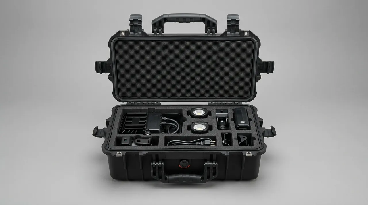
Drive components are the conveyor's power source, and their protection focuses on three fragile structures: shaft extensions, tooth flanks, and springs.
Gearboxes. The output shaft extension needs a rigid sleeve to prevent radial loading that bends the shaft or damages the oil seal. The mounting flange register is the location datum and needs a plastic cover. The oil seal area should not be held under sustained lateral pressure, which causes weeping. Gearboxes are heavy, so provide a load-bearing deck and rigid stops.
Sprockets and chains. Struck tooth flanks create meshing impact, so give them separate cavities wrapped in anti-rust paper. Coil and secure chains so they cannot swing and abrade inside the case.
Tensioners. A spring held under compression in transit can take a permanent set. Restrain it in the as-built pre-compressed state and protect the screw threads. Thread protection depends on avoiding direct metal-to-metal contact and fitting a sleeve or wrap so the thread form is not struck.
Frame side plates and guards. These are folded thin-gauge parts where flatness and hole position matter. Stand them upright in separate cavities with edge protectors to prevent rolled edges.
| Drive component | Critical weak point | Protection measures | Can share a case |
|---|---|---|---|
| --- | --- | --- | --- |
| Gearbox | Shaft extension, flange register, oil seal | Shaft sleeve, flange cover, load-bearing deck | With motor |
| Motor | Shaft extension, terminal cavity | Moisture barrier bag, dust plug | With gearbox |
| Servo motor | Shock acceleration, ESD | Isolated damped cavity, ESD bag | Not recommended |
| Encoder | Code disc, shaft, connector | Isolated damped cavity, ESD bag | Must be isolated |
| Sprocket and chain | Tooth flanks, links | Separate cavity, anti-rust paper | Zoned in same case |
| Tensioner | Spring, threads | Pre-compressed restraint, thread sleeve | Zoned in same case |
| Frame side plate | Flatness, hole position | Upright cavity, edge protector | Zoned in same case |
8. Motorized Drums and Servo Drives: Electrical Protection and Vibration Isolation
A motorized drum integrates the motor and reduction gear inside the roller body, making it the highest value-density and hardest-to-protect component on a conveyor line.
Sealing and moisture protection. Internal insulation is sensitive to moisture, so use a moisture barrier bag with desiccant and place a humidity indicator card inside. With a sealed case, also consider condensation from temperature cycling.
Vibration isolation. A motorized drum contains a rotor, bearings, and gears and is sensitive to shock acceleration. Use a combination of rigid stops and low-stiffness elastic support to bring peak shock acceleration within the component's tolerance. Models with encoders need stricter vibration control still.
ESD protection. Models with built-in control circuits and sensors are ESD sensitive. Use anti-static shielding bags and perform unpacking at an ESD workstation or with a wrist strap. Related solutions are discussed in ESD shielding cases.
Wiring and connectors. Coil and secure cables to avoid pulling damage at the connector root, and fit protective caps on plugs.
Temperature adaptability. If the transport route includes extreme high or low temperatures, note that coatings and seals can become brittle in the cold; see extreme temperature case solutions.
9. Sealing and Ingress Protection: An IEC 60529 and GB/T 4208 View
IEC 60529 and the equivalent national standard GB/T 4208 define how IP ratings are judged. Recommendations for conveyor roller and parts cases:
| Scenario | Recommended rating | Notes |
|---|---|---|
| --- | --- | --- |
| In-plant circulation and covered short haul | IP54 | Dust focus |
| Domestic long-haul road transport | IP65 | Dust tight plus jet-water resistant |
| Export sea freight and open storage | IP67 | No ingress after temporary immersion |
| Motorized drum and electrical parts case | IP67 recommended | Combines moisture and water ingress protection |
The three critical sealing components are the gasket, latches, and hinges. Gasket material - silicone, EPDM, or TPE - determines weather resistance and compression set; a comparison is given in case seal material selection comparison. Latch count and type determine clamping uniformity, and custom latch options are covered in case lock customization options.
Note that roller cases are usually large with long openings, and increased sealing perimeter length makes flatness control significantly harder. Large cases therefore need more latches and higher case stiffness rather than simply a larger gasket section.
10. Rust Prevention and Cleanliness: The Hidden Risk at Shaft Ends and Bearings
Corrosion risk for rollers concentrates in three places: shaft ends, bearing housings, and the roller face itself on galvanized carbon steel rollers.
Oil film protection. Factory condition normally includes anti-rust oil. Packaging materials must not absorb oil, or the film is wiped away and protection is lost. Avoid highly absorbent cardboard and low-density foam in direct contact with oiled surfaces.
VCI vapour-phase protection. Use vapour-phase corrosion inhibitor inside a sealed case to form a protective film on complex surfaces such as shaft ends and threads, which are difficult to oil. Case sealing is mandatory for this to work.
Desiccant. In a well-sealed case, silica gel is typically dosed at roughly 0.5 to 1.0 kg per cubic metre of free volume, adjusted for transit duration, packaging moisture vapour transmission rate, and destination climate.
Cleanliness control. This matters especially for rollers. Bearing contamination is a classic delayed-onset failure, and foam debris from insert machining, wood dust from crates, and metal chips can all be contamination sources. Vacuum-clean CNC-routed foam after cutting and keep the packing area clean. Cleaning practice is covered in protective case cleaning and care.
Recommended sea freight combination: VCI film, desiccant, IP67 sealed case, and a humidity indicator card, with a shock indicator label inside to create a traceable transport evidence chain.
11. Transport Vibration and Shock Validation: GB/T 4857.23 and ISTA
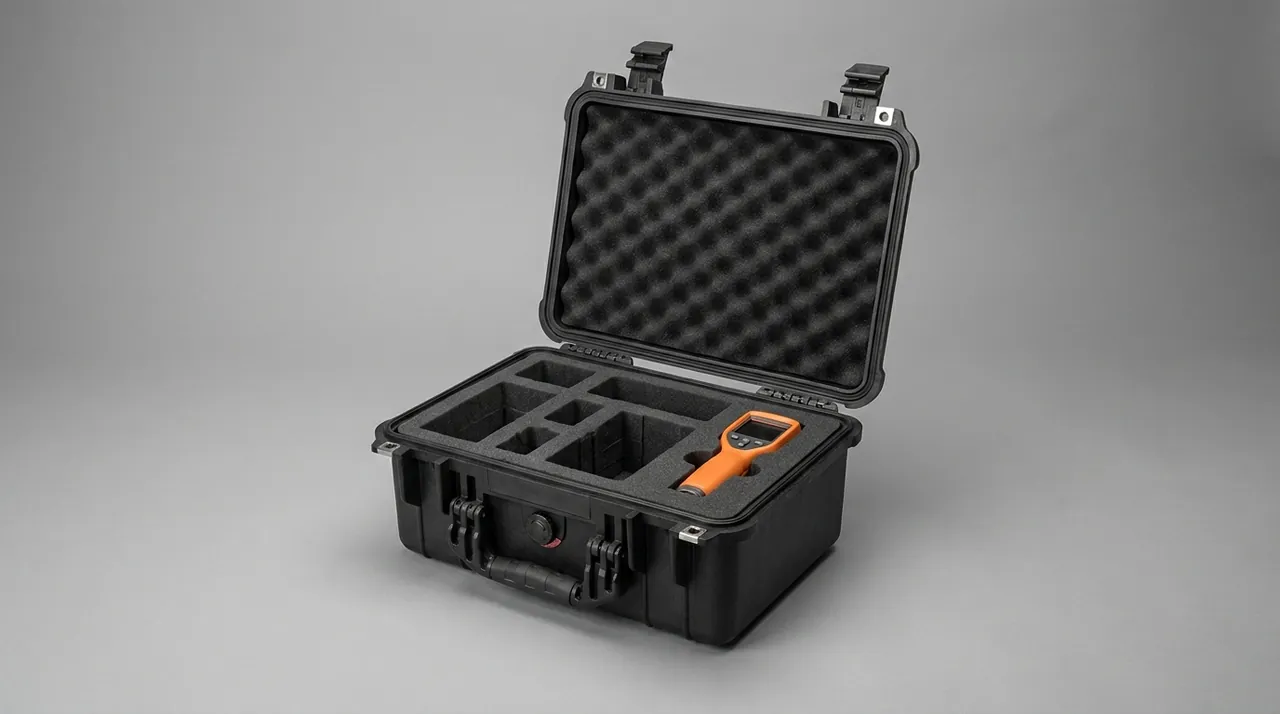
The GB/T 4857 series is the national framework of basic transport package test methods, and GB/T 4857.23 specifies random vibration methods to simulate real transport spectra. It is the core method for verifying roller location stability and insert resistance to collapse; the system is explained in GB/T 4857 transport packaging standard explained.
The ISTA series approaches this from the distribution chain with Series 1 (non-simulation integrity), Series 2 (partial simulation), Series 3 (general simulation), and Series 7 (development) programs. For door-to-door delivery of rollers and drive components to project sites, ISTA 3A and 3E are a reasonable reference; see choosing ISTA transport test procedures.
| Test | Reference standard | Example condition | Failure of interest |
|---|---|---|---|
| --- | --- | --- | --- |
| Random vibration | GB/T 4857.23 / ASTM D4728 | Road spectrum scaled to distance | Roller rolling, insert collapse, bearing contamination |
| Fixed-frequency vibration | GB/T 4857.7 | Selected frequency and acceleration | Bending resonance, fastener loosening |
| Drop | GB/T 4857.5 / ISTA 1A | Height set by mass | Case cracking, shaft end deformation |
| Stacking | GB/T 4857.3 / GB/T 4857.4 | Load and duration per stack | Case creep, roller ovalisation under load |
| Conditioning | GB/T 4857.2 | High humidity and temperature cycling | Seal ageing, condensation |
| Combined environmental | MIL-STD-810H (test method reference only; not a military certification) | Temperature, humidity, vibration, shock combined | Combined fitness |
MIL-STD-810H provides a systematic environmental test methodology. It must be stated clearly that citing it is a test method reference only; it does not represent a military certification, nor any defence procurement qualification. Compliant wording is discussed in MIL-STD-810H case environmental testing explained.
12. Stacking, Lifting and Heavy-Load Handling Awareness
Stacking. Stacking roller cases requires care. Even with proper inserts, the weight of an upper case transmitted through the insert to the rollers can cause slight bending. Three rules apply: limit stack height and mark it prominently; if stacking is unavoidable, use an interlayer load-bearing frame so upper weight passes directly into the case walls rather than the rollers; and do not stack large-diameter heavy roller cases at all.
Lifting. Very long roller cases and heavy drive component cases should have four symmetric lifting points with rated load marked and local reinforcement around the points. Single-point lifting that twists the case is prohibited.
Forklift handling. Provide standard fork pockets and mark insertion direction on the side. Very long cases must use twin forks or a spreader.
Personnel protection. Mark a lifting exclusion zone, provide safety footwear and gloves, appoint a single signal person, and be alert to the roller rolling hazard.
Safety note: a roller that loses restraint rolls very easily, and a stacking or lifting instability can trigger a cascading collapse. The consequences of such incidents are far more serious than cargo damage alone.
13. Labelling, Traceability and Site Delivery Management
The labelling system should cover four layers:
- Case master label: project number, case number, roller diameter and length specification, quantity, gross and net weight, stack limit, lifting marks.
- Component label: model, material, coating type, batch number.
- Tamper evidence: one-time seals or tamper-evident labels so en-route opening can be detected.
- Environment marking: temperature-sensitive notices for coated and electrical parts, and do-not-invert notices.
For site delivery, pack by installation unit: rollers and drive components for the same conveyor segment or sorter module go into the same case group, labelled with line and module numbers to reduce secondary sorting. For projects requiring open-case sampling, build the rules on the approach described in custom case acceptance sampling with AQL.
14. OEM/ODM Customization, Acceptance and Maintenance
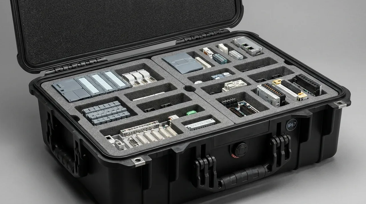
A customization workflow has six stages: requirement intake (roller diameter and length series, annual volume, transport route), concept design (case series, insert concept, sealing and vibration design), prototype validation (first-article trial fit, clearance checks, drop and vibration pre-testing), pilot run, volume supply with batch traceability, and iteration.
Supplier evaluation should focus on structural design capability, insert machining accuracy, ability to supply test documentation, and delivery reliability. The methodology is set out in how to choose a protective case OEM factory. JUNZHJIA is manufactured by Kexin New Materials (Guangdong) Co., Ltd. and supports conveyor manufacturers, specialist roller factories, and OEM/ODM customers with integrated services from structural design and insert customization through volume delivery. A standard case series can be built by roller diameter and length, seals and hardware matched per model, and supporting test documentation provided for tendering and acceptance. Buyers should also guard against counterfeit products, since differing seals and materials cause protection failure; see identify genuine vs fake protective cases.
Acceptance points should cover appearance (case cracks, gasket integrity), tamper evidence, humidity indicator colour, and sampled components (roller face roundness and scoring, shaft end dimensions and burrs, coating integrity, sprocket tooth flanks, electrical part condition and insulation).
Maintenance and life management. Wipe inserts with a soft cloth and mild detergent. After every reuse cycle, inspect gaskets for compression set and ageing. Periodically lubricate and check hinge and latch fasteners. Keep a case-number register with mandatory inspection points set by cumulative cycle count. Wheels and trolley handles on wheeled cases are wear parts; configuration and replacement are covered in case wheels and trolley handle configuration.
Frequently Asked Questions
Q: A roller looks like just a steel tube. Why can't it simply be bundled or packed in a crate with filler?
A: Because a roller's value is not in the steel but in the geometric accuracy of its face and the fit accuracy of its shaft ends, and once either is lost it is effectively unrecoverable on site. Bundling and crate filling cause four classes of damage. First, roller faces contacting each other or the straps produce scratches and dents. Second, stacking pressure ovalises thin-walled rollers, so each rotation produces one impact, generating periodic vibration and noise and accelerating bearing wear. Third, struck shaft ends develop burrs or bend, causing eccentric assembly and tracking deviation. Fourth, wood dust, foam debris, or metal chips entering bearing raceways surface only weeks after commissioning as noise and temperature rise, and tracing them is difficult. There is a deeper geometric reason as well: contact between a cylindrical surface and a flat surface is essentially line contact at high stress, and the roller rolls easily, so plain foam cannot restrain it. Dedicated location schemes such as vertical slots, horizontal half-round slots, or shaft-end suspension are essential.
Q: How should packing method vary with roller diameter?
A: Grade by diameter and rigidity. Small diameter rollers, roughly 20 to 50 mm, have low rigidity and poor bending resistance, so vertical divider slots are recommended with shaft ends entering locating bores so the roller face touches nothing else, while avoiding long unsupported spans. Medium diameter rollers, roughly 50 to 89 mm, are the workhorse of general conveying lines, and horizontal half-round slots with layering work well, since the half-round profile creates a large contact area at low stress. Large diameter rollers above about 89 mm are heavy with high inertia, so carefully verify support count, case load capacity, and lifting method, using layered slots with end stops. For rollers longer than 2,000 mm, rigidity drops further and multi-point soft support is mandatory, with spacing empirically within one third of roller length to avoid first-mode bending resonance under transport vibration. For a roller factory, the more economical approach is to build three to five standard case types by diameter band and adapt them to different lengths with replaceable insert plates.
Q: What special requirements apply to coated rollers?
A: Three points stand out. First, coatings have low hardness and poor scoring resistance, so contact with any hard object or compression can leave a permanent dent; the roller face must therefore never touch a hard support, favouring shaft-end suspension so the face touches nothing, or a tightly fitting half-round foam slot giving surface contact. Second, the bond interface between coating and core can delaminate under shear shock, so rollers must not collide with each other and must not roll sideways in transit. Third, coatings are contamination sensitive, and oil, dust, and foam debris can penetrate and change the coefficient of friction, so wrap the face with a protective film and verify that insert materials are compatible with the coating - some foams retain acidic residues or plasticizers that can age the coating. If the transport route includes low temperatures, coatings can become brittle, so consider extreme temperature conditions and mark the case with a temperature-sensitive notice.
Q: What is the fundamental difference between packing a motorized drum and packing a gravity roller?
A: The difference is that a motorized drum is a precision electromechanical assembly with built-in drive and control, while a gravity roller is simply a rotating member. That creates four extra requirements. First, moisture protection: the winding and circuitry inside a motorized drum are moisture sensitive, so a barrier bag with desiccant and a humidity indicator card are essential, because moisture directly reduces insulation resistance. Second, vibration isolation: the internal rotor, bearings, gears, and possible encoder are sensitive to shock acceleration, requiring a combination of rigid stops and low-stiffness elastic support to bring peak acceleration within tolerance. Third, ESD protection: models with built-in control circuits need anti-static shielding bags and unpacking under ESD-controlled conditions. Fourth, electrical connection protection: cables should be coiled and secured against pulling, with protective caps on plugs. Motorized drums are also high value and should be cased separately rather than mixed with heavy or sharp metal parts.
Q: How should the sealing class for roller cases be set, and what makes high IP ratings difficult on large cases?
A: Set the class from the worst condition in the transport and storage chain. For in-plant circulation and covered short-haul delivery, IP54 is usually sufficient. Domestic long-haul road transport calls for IP65. Export sea freight, open storage, and quay transfer call for IP67, and cases containing motorized drums or other electrical parts should be IP67 or better for the whole case. The difficulty with large roller cases is sealing perimeter length: large dimensions and long openings substantially increase the gasket run, and flatness plus uniform compression become much harder to control. Simply enlarging the gasket section does not solve this and can even create local failure from uneven compression. The correct path is more latches, a multi-point clamping structure, higher case stiffness to control deflection, and machined flatness on the sealing face. The judgement basis comes from standardised IEC 60529 and GB/T 4208 testing, but real performance depends on gasket material and compression, latch distribution, and case stiffness acting together, so validate a production case as a complete unit.
Q: Why is bearing contamination described as the most hidden cause of roller failure?
A: Because it exhibits delayed onset. Metal chips, grit, foam debris, or wood dust entering a bearing raceway does not cause immediate failure; instead it surfaces weeks to months after commissioning as noise, temperature rise, and increasing vibration. By then the equipment is in production, so stopping the line for investigation is costly, and tracing the contamination source - packaging, assembly, or operating environment - is difficult. The problem is often misdiagnosed as a product quality defect, making liability allocation contentious. Control operates at three levels. Source control means thoroughly removing debris after insert machining and avoiding packaging materials that shed particles. Process control means keeping the packing area clean and prohibiting packing near cutting or grinding operations that generate dust. Isolation control means fitting dust caps on bearing housings and protecting critical fit surfaces with film or sleeves. Case cleaning between reuses also matters, because debris left from a previous shipment can contaminate the next.
Q: What is the mechanism by which transport vibration damages rollers, and how is it validated?
A: The mechanism has three layers. The first is resonance: as a slender body of revolution, a roller has a low first bending natural frequency that couples with the low-frequency band of road transport vibration, roughly 5 to 20 Hz, causing the roller to flex and jump inside the case and then strike neighbouring rollers or the case wall. The second is insert fatigue: sustained vibration causes foam compression fatigue and collapse, so previously snug slots open up and components begin to migrate; damage typically occurs in the second half of the journey. The third is fasteners and contamination: vibration can loosen fasteners and can also cause residual debris to migrate inside the case and reach bearing fit surfaces. For validation, domestic projects should use GB/T 4857.23 random vibration testing, the core method for verifying insert and location stability. Where resonance amplification at a specific frequency must be assessed, use GB/T 4857.7 fixed-frequency vibration. International projects can reference ASTM D4728 and ISTA Series 3 programs. Standard selection should match the real route.
Q: How should on-site acceptance of rollers and drive components be carried out?
A: Follow the sequence: determine first, inspect second, register third. Step one is determining before opening: check whether the shock indicator has triggered, whether the humidity indicator card has changed colour, and whether tamper seals are intact, to establish whether out-of-limit shock, moisture exposure, or opening occurred, and photograph everything to support liability allocation. Step two is visual inspection: for rollers, check roller faces for scratches and dents, look for abnormal roundness, check shaft ends for burrs or deformation, and verify coating integrity; for drive components, check shaft extensions and flange registers, look for oil seal weeping, inspect sprocket tooth flanks for impact damage, and verify electrical part condition and insulation. Step three is dimensional sampling: sample critical fit dimensions such as shaft end diameter and length and mounting hole pitch to confirm they are within tolerance. Step four is registration and traceability: record results, batch numbers, and case numbers, quarantine and tag any anomalies rather than "trying it first." Step five is returning empty cases and updating the register for circulation reuse.
Q: How should a roller factory plan its parts case series?
A: The guiding idea is to trade case commonality for cost and efficiency. A roller factory usually offers many diameters and lengths, and tooling each one separately rapidly inflates tooling and inventory cost. Three practices help. First, divide diameters into three to five standard case types - for example small, medium, large, and very long roller cases - with case dimensions and insert slots designed for the largest size in each band. Second, adapt to different diameters and lengths with replaceable insert plates that are standardised and batch-produced, so switching specification means switching a plate rather than a whole case. Third, match case dimensions to truck and container internal profiles to raise load fill, and consider nestable or collapsible empty cases to cut return cost. It also helps to map the case series to roller product model numbers and embed that mapping in production and shipping workflows so storage and site delivery stay organised. JUNZHJIA can assist customers at the concept stage with case series planning and standardised insert design.
Conclusion & Related Reading
Protecting conveyor rollers and drive components in transit comes down to solving two families of problems: rotational precision and electromechanical safety. Roller face roundness, shaft end fit, bearing containment, and coating integrity belong to the first. Moisture, vibration, and ESD protection for motorized drums, servo motors, and encoders belong to the second. The sealing integrity and stacking capacity of the case determine whether protection remains effective across the whole route.
The selection path condenses to one sentence: first define location and vibration isolation from roller diameter and component nature, then define sealing and rust-prevention class from the transport route, and finally build a standard case series around the roller factory's product range to balance protection with management efficiency. For conveyor manufacturers and specialist roller factories needing custom inserts, OEM/ODM volume supply, or supporting test documentation, JUNZHJIA provides integrated support from case series planning and structural design through volume delivery.
Related Reading