

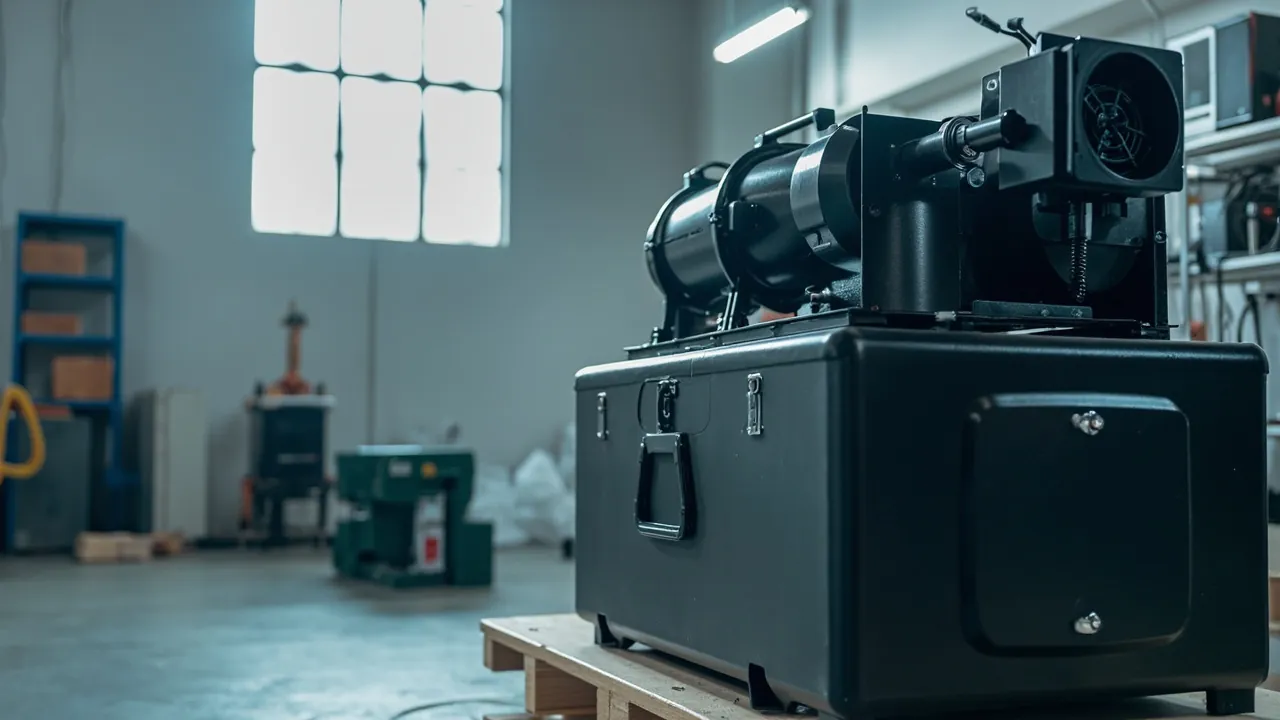
Transit damage to HVAC equipment concentrates in three component families: compressors suffer from vibration, coils suffer from compression, and fans suffer from deformation. These three failure mechanisms are entirely different, yet they are routinely shipped inside the same generic wooden crate. The result is cracked compressor piping, collapsed coil fins and out-of-balance fan impellers on arrival. HVAC equipment adds a second complication: it is large, weight-concentrated and irregularly shaped. A commercial VRF outdoor unit may weigh 200 to 600 kg with its centre of gravity offset toward the compressor, while a heat-exchange coil may have tube walls under 0.5 mm and fin spacing of 1.4 to 2.2 mm, so a hand pressed flat against the surface can flatten a patch of fins. Packaging for HVAC equipment therefore cannot follow a whole-machine packing logic. It must be designed as a two-layer system of component-level protection plus whole-unit restraint.
This article is written for packaging engineers and procurement staff at air-conditioning OEMs, component suppliers, installation contractors and export trading firms. It works through the protection requirements for compressors, fans and coils, then provides a component-to-case selection matrix, lining material comparison, sealing and flammability requirements, transport test standards and a packing SOP. All figures are typical industry values or empirical ranges; the governing inputs are the component drawing, the machine's centre-of-gravity data and the customer's acceptance specification. JUNZHJIA supplies model-specific custom inserts, vibration-damping structures, OEM and ODM programmes, and supporting test documentation for HVAC equipment cases.
Table of Contents
- 1. Why HVAC Equipment Is Harder to Package Than General Machinery
- 2. Compressor, Fan and Coil: Three Failure Modes Compared
- 3. Compressor Cases: Vibration, Tilt and Service-Port Protection
- 4. Fan Cases: Three Risk Points at Impeller, Bearing and Motor
- 5. Heat-Exchange Coil Cases: Zero-Crush Fin Design
- 6. Component-to-Case Selection Matrix
- 7. Lining Materials and Damping Structures Compared
- 8. Sealing, Moisture Control and IP Ratings: IEC 60529 and GB/T 4208
- 9. Flammability and Material Compliance: Where UL94 Applies
- 10. Transport Test Basis: ISTA, GB/T 4857, ASTM D4169 and MIL-STD-810H
- 11. Packing SOP and Site Unpacking Management
- 12. Sea Export, Returnable Re-Use and OEM/ODM Customisation
- Frequently Asked Questions
- Conclusion and Further Reading
1. Why HVAC Equipment Is Harder to Package Than General Machinery
The packaging difficulty of HVAC equipment can be reduced to four mismatches.
Weight and volume mismatch. The compressor is the heaviest single item in the machine, commonly 30 to 150 kg and up to 200 kg or more for large scroll or screw units, yet it occupies only a small part of the machine's projected area. The coil is physically enormous but extremely light and fragile. One machine therefore presents both a high-pressure-per-unit-area requirement and a low-pressure requirement at the same time, and a single uniform foam layer cannot satisfy both.
Stiffness and brittleness mismatch. The casing and frame are rigid structural parts that can carry some stacking load. Coil fins and fan impellers are quasi-brittle thin-wall elements that deform irreversibly under compression. The packaging scheme must therefore separate roles: rigid parts carry load, fragile parts are isolated.
Transport environment versus design duty mismatch. The equipment is designed to operate in a well-ventilated plant room or on a roof where vibration is controlled. Transport subjects it to hours of random vibration, sudden handling shock, and 30 to 45 days of high-humidity salt fog on a sea crossing. The fatigue effect of vibration on compressor suction and discharge piping, especially at welded joints, is far greater than its effect on the casing.
Returnable demand versus one-way cost mismatch. Project work often ships on a one-way basis with the packaging discarded after installation, while OEMs and rental operators need returnable cases. The selection logic differs: one-way packaging is judged on unit cost and minimum protection, while returnable packaging is judged on service life, maintainability and amortised cost per trip.
One easily overlooked fact: most hidden HVAC transit damage is invisible on arrival. A micro-crack in compressor piping, slight fan impeller deformation or a locally collapsed coil fin often only shows up weeks later as refrigerant loss, abnormal noise or reduced heat-exchange efficiency. The value of packaging verification is therefore not merely intact arrival but reliable operation.
With these four mismatches in mind, it becomes clear why an HVAC transport case needs two layers of design: component-level custom inserts plus whole-unit restraint. The sections that follow classify the failure modes first, then address each family in turn.
2. Compressor, Fan and Coil: Three Failure Modes Compared
In after-sales data, transit damage to HVAC equipment clusters tightly around three component families, and the triggers are clearly identifiable.
| Component | Primary failure mode | Trigger | Typical consequence | Priority countermeasure |
|---|---|---|---|---|
| --- | --- | --- | --- | --- |
| Compressor | Suction and discharge weld cracking, loosened mounting bolts | Cumulative random vibration, loss of centre-of-gravity control | Refrigerant leakage, performance loss | Low-rebound damping pad plus rigid foot restraint |
| Compressor | Service port deformation, internal component displacement | Transport tilt beyond permitted angle, drop | Cannot evacuate or charge | Orientation marking plus anti-tilt restraint plus port caps |
| Fan | Impeller deformation, loss of dynamic balance | Lateral squeeze, hard contact with case wall | Vibration and noise exceed limits, early bearing failure | Dedicated impeller cavity plus axial restraint |
| Fan | Bearing damage, terminal box moisture ingress | Axial shock, humidity attack | Abnormal starting current | Axial support plus desiccant plus sealing |
| Coil | Fin collapse, loss of heat-exchange area | Stacking pressure, manual handling, hard-object contact | Lower efficiency, higher air-side pressure drop | Surface-contact guard panel plus fin-direction clearance |
| Coil | Header connection deformation, copper tube kinking | Unsupported span or over-tight strapping | Difficult weld repair, leakage | Header support saddle plus ban on single-point strapping |
| General | Coating scuffing, sheet-metal rusting | Rubbing plus high humidity plus salt fog | Poor appearance, shorter corrosion life | Conforming pad plus barrier film plus anti-rust treatment |
All seven modes share a common trait: damage originates in transit and appears in operation. This is the fundamental reason the HVAC industry needs pre-shipment transport verification. It is also worth stressing that the priority order of failure modes depends strongly on transport mode. Short-haul road transport is dominated by handling shock and stacking pressure, while sea export is dominated by cumulative vibration, humidity and salt fog. The same compressor should be protected to different levels for domestic distribution and for export by sea.
3. Compressor Cases: Vibration, Tilt and Service-Port Protection
The compressor is the highest-value-density and most vibration-sensitive component in an HVAC machine. Its protection addresses three things: vibration isolation, attitude control and service-port protection.
Vibration isolation. Compressors are usually mounted on rubber damping feet relative to the frame, but those feet are designed for the operating condition and their natural frequency targets the motor speed. The transport excitation band is wider and higher in amplitude, so the original feet are often insufficient. Transport cases need second-stage isolation: place low-rebound, low-natural-frequency padding beneath the compressor base or the machine feet so transport vibration cannot reach the piping through a rigid path. The load path should run compressor, damping pad, load block, case floor, pallet, rather than compressor, soft foam, case sidewall. The same principle governs cushion lining and case floor interaction.
Attitude control. Scroll and screw compressors usually carry explicit tilt limits, and exceeding them can disturb internal lubrication and fit conditions. The case should do two things. First, form three-dimensional restraint through a reinforced support block on the centre-of-gravity side and a locating pressure block on top, preventing the unit from sliding. Second, apply prominent centre-of-gravity, permitted-tilt and this-way-up labels to the outside, and provide a means of verifying attitude on arrival, such as a tilt indicator or an intact seal, so it is clear whether a tip-over occurred.
Service-port protection. Suction, discharge and process ports are the features most easily bent or contaminated in transit. The engineering practice is to cap the ports with dedicated plugs or plastic inserts first, then fit a soft protective sleeve outside, and never let padding press directly on a port face. Copper tubes protruding from the casing need their own clearance cavity so they cannot contact the case wall or another component.
Feet and fasteners. Compressor mounting bolts can loosen under vibration and allow position drift. Verify fastening torque before packing, and provide locating pockets in the insert for the feet so position can be reproduced and any drift is immediately visible on arrival.
Refrigerant and oil. Some compressors ship pre-charged with refrigerant or oil. Confirm that port caps are sealing correctly, and place oil-absorbent material in the case to handle an unexpected leak. For export, note destination-market declaration requirements for refrigerant-containing equipment, and make sure case labelling is consistent with the accompanying compliance documents. JUNZHJIA typically builds these component cases with a composite insert of low-rebound EVA damping layers over structural foam load blocks, issuing an insert drawing against the compressor model and the machine's centre of gravity for approval before tooling.
4. Fan Cases: Three Risk Points at Impeller, Bearing and Motor
Fan transport risk concentrates at three points: impeller, bearing and motor wiring.
Impeller. Centrifugal fan impellers are usually thin-plate pressings or weldments with low blade stiffness, and they are most vulnerable to lateral squeeze and hard contact. The common failure in transit is direct contact between impeller and case wall, or stacking of other components on top, producing local deformation. Once deformed, dynamic balance is destroyed, which appears as excessive vibration and noise, and is very difficult to correct on site. The correct approach is a dedicated impeller cavity: a ring support or curved cradle blocks the impeller in position so it touches no rigid surface, combined with axial restraint to stop it sliding along the shaft.
Bearing. Bearings are sensitive to axial shock. A drop during handling or a single-point lift transmits through the shaft into the bearing raceway and produces brinelling, which later shows up as abnormal noise and early failure. The countermeasure is axial support: fit an axial limit block at the motor shaft extension so the bearing is not directly loaded by axial acceleration.
Motor wiring. Terminal boxes and cable exits are prone to moisture and compression. Fit a protective sleeve over the cable exit, include desiccant and a humidity indicator card in the case, and where the temperature swing is large, add a pressure equalisation valve to handle the breathing effect.
Dampers and actuators. If the machine includes motorised dampers or proportional actuators, these electronic and plastic-geared components need their own compartments so the fan or casing cannot press on them. Managing such wandering small parts is best handled with a removable divider system.
Case format. Fan components are usually medium-sized and irregularly shaped, suiting a medium case with a custom insert. For whole-machine shipment, use a combination of frame restraint plus dedicated fan protection: first fix the fan's relative position inside the machine using timber or metal profile, then restrain the whole unit inside the outer case.
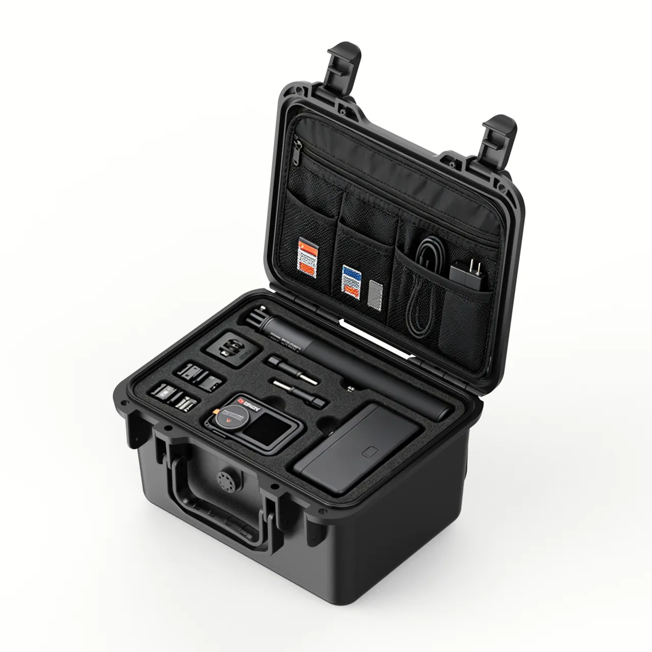
5. Heat-Exchange Coil Cases: Zero-Crush Fin Design
The heat-exchange coil, whether evaporator, condenser or cooling coil, is the most fragile and most frequently underestimated component in HVAC equipment. Its characteristics are large surface area, thin wall, dense fins and high value.
Why fins collapse. Fin thickness is typically 0.1 to 0.15 mm with spacing of 1.4 to 2.2 mm, making a quasi-brittle thin-wall structure. Collapse has three main triggers: stacking pressure applied directly to the coil face, manual handling that grips the finned area, and hard objects such as bolts, tools or other metal parts rubbing against the fins under vibration. Once a large area collapses, air-side pressure drop rises and heat-exchange efficiency falls, and the damage cannot be repaired on site.
The core principle is surface contact and the elimination of point contact. In practice this means the following.
- Cover both coil faces with rigid guard panels, such as corrugated board, plastic sheet or thin plywood, sized close to the coil face area so external force is distributed as a surface load.
- Add a soft separation layer between guard panel and fins, such as PE foam film or non-woven fabric, so the panel itself cannot scuff the fins.
- Never use cord or narrow strapping directly around a coil. If strapping is unavoidable, use wide webbing with corner protectors at contact points.
- Stand the coil upright or in the design attitude so fin direction does not carry sustained gravitational pressure.
- Headers, both distribution and collection, are relatively flexible copper tubes and need dedicated support saddles so they are never left spanning unsupported.
Coil-to-case relationship. Coils are normally shipped inside the machine rather than on their own, so the practical scheme works on two levels. Inside the machine, guard panels and limit blocks fix the coil's relative position. Inside the outer case, load-bearing structures carry the machine's weight so that weight is never transmitted through the coil. This is where mistakes are most common: treating the coil as a load-bearing member is the classic design error in HVAC packaging.
Corrosion protection and cleaning. Coil fins usually carry a hydrophilic or anti-corrosion coating, and scuffing destroys the coating and creates a rust initiation site. Avoid using wet materials in transit that could leave residue. For sea export, add a barrier film and desiccant. If fins collect dust on arrival, clean with low-pressure compressed air or a soft brush, never a high-pressure water jet, which will deform the fins.
6. Component-to-Case Selection Matrix
The matrix below gives selection guidance for common HVAC components. Values are typical recommendations; measured weight, centre-of-gravity position and the actual transport route always govern.
| Component | Typical weight | Insert scheme | Case format | Sealing guidance | Critical constraints |
|---|---|---|---|---|---|
| --- | --- | --- | --- | --- | --- |
| Scroll or rotary compressor | 30-90 kg | Low-rebound EVA damping layer over structural foam blocks | Medium reinforced case | IP65 | Rigid foot restraint, port clearance |
| Screw compressor | 150-400 kg | High-density load blocks with steel pallet plate | Heavy frame case | IP65 | Offset centre of gravity, permitted tilt angle |
| Centrifugal fan | 20-120 kg | Ring support plus axial restraint | Medium case with insert cradle | IP65 | Dedicated impeller cavity, axial shock |
| Axial fan | 10-60 kg | Curved cradle blocks with soft facing | Medium case | IP65 | Blade clearance, shell deformation |
| Heat-exchange coil | 15-80 kg | Rigid guard panel plus soft separator plus header saddle | Long flat case | IP65/IP67 | Surface contact, no point contact |
| Control box or VFD module | 10-50 kg | Low-rebound EVA full floating wrap | Medium case with castors | IP65 plus desiccant | Vibration, moisture, ESD |
| Accessories (bolts, couplings) | Under 20 kg | Compartmented accessory box | Internal or clip-on | IP65 | Packing list label, loss prevention |
Two empirical rules are worth remembering. Once a component exceeds roughly 60 kg, assume manual handling will eventually fail, so the case must offer mechanical lifting or forklift capability. Once a component contains fins or thin blades, assume that someone will eventually grab that area by hand, so guard panels and limits must be designed to survive being handled that way without deformation.
7. Lining Materials and Damping Structures Compared
Lining selection for HVAC equipment is more complex than for general machinery because it must serve both heavy-part damping and fragile-part protection.
| Material or structure | Typical density | Damping behaviour | Load capacity | Best-fit components | Cautions |
|---|---|---|---|---|---|
| --- | --- | --- | --- | --- | --- |
| Low-rebound EVA | 40-120 kg/m3 | Good energy dissipation, stable under repeated excitation | Medium | Compressors, control boxes | Slightly soft when hot; verify temperature rating |
| PU foam | 25-60 kg/m3 | Medium-low rebound | Medium-low | Fans, general parts | May collapse under long compression |
| XPE/IXPE | 30-80 kg/m3 | Medium rebound, good weatherability | Low | Coil separation layers, thin panels | Not suitable as a load bearer |
| Structural foam (cross-linked PVC/PE) | 60-300 kg/m3 | High rigidity, low deformation | High | Compressor load blocks | Requires CNC machining; higher cost |
| Rubber damping pad | Graded by hardness | Effective low-frequency isolation | High | Compressor foot second-stage isolation | Must be selected against load and frequency |
| Corrugated or honeycomb guard panel | Not applicable | No damping, distributes surface load only | Medium | Coil fin face protection | Needs a soft separator layer |
Three-step selection logic. First define the load by calculating the pressure per unit area the component applies to the pad. Second define the frequency band by estimating the dominant transport excitation band and ensuring the pad's natural frequency does not fall inside it, otherwise the pad will amplify rather than isolate vibration. Third define the handling frequency: one-way shipment can favour rigidity, repeated cycles favour toughness, and the lining's wear resistance and cleanability become part of the calculation.
Where handling frequency is high, treat the lining as a serviceable item rather than a permanent part of the case. Composite linings are standard practice: structural foam in load-bearing zones, EVA, PU or felt in contact and cushioning zones. Before volume production, run a trial fit and a short-route transport check and let the measured result rather than the material data sheet decide the specification. The full route from 3D data to finished insert is covered in EVA insert customisation process and custom foam insert design guide, with material comparisons set out in protective case foam material comparison. JUNZHJIA normally issues a zoned insert proposal based on the machine's centre of gravity and component layout, then confirms it with a first-article trial fit and a short transport check before volume production.
8. Sealing, Moisture Control and IP Ratings: IEC 60529 and GB/T 4208
HVAC equipment faces widely varying transport environments. Domestic distribution is mostly dry overland freight, while sea export brings high humidity, salt fog and temperature swing. The goal of sealing design is a match to the environment, not maximum tightness.
What the IP code means. The IP code defined in IEC 60529 uses two digits, the first for solids protection from 0 to 6 and the second for water protection from 0 to 9K. The equivalent Chinese standard is GB/T 4208. Typical configurations for HVAC cases are IP54 for short domestic routes with covered transport, IP65 for the large majority of components on domestic and near-sea routes, IP67 for sea freight, open-air storage and high-humidity regions, and IP68 only for extreme scenarios such as vessel decks and long-term outdoor storage.
Important note: an IP rating verifies that external water does not enter. It does not mean the inside stays dry. A well-sealed case actually traps internal moisture, since after a day-night temperature cycle the internal air cannot exchange. For HVAC equipment containing control boards and terminal boxes, this is a common cause of failed insulation tests on arrival. Sealing, desiccant and a humidity indicator card should therefore be treated as a standard combination, with a pressure equalisation valve added on routes with large temperature swings.
Seal selection. Case sealing relies on gasket profiles, commonly silicone, EPDM and foamed TPE. Silicone offers the best temperature and weathering resistance at higher cost. EPDM balances ageing resistance and weatherability for outdoor duty. Foamed TPE has low compression set and suits cases that open and close frequently. The gasket cross-section, whether O-profile, D-profile or adhesive-backed U-profile, must match the case groove, as detailed in hinge, latch and seal selection. Seals are wear items and belong on the spare parts list, with replacement intervals driven by open-close count and storage environment.
Latches and hinges. HVAC cases are large and their lids heavy, so latch count must match lid stiffness. When lid length exceeds 800 mm, three or more latches are advisable to prevent the middle lifting and breaking the seal. Hinges should be load-bearing metal parts with corrosion protection, and sea-freight specifications should raise the corrosion class.
Moisture and rust control. Equipment containing copper tube, aluminium fins and carbon-steel framing is highly humidity-sensitive. Use an effective desiccant with a humidity indicator card, apply anti-rust treatment to bare metal surfaces, and cap copper tube ends. For long-term storage, inspect and renew desiccant periodically.
9. Flammability and Material Compliance: Where UL94 Applies
UL94 is a flammability classification standard for plastic materials. It rates case plastic parts, insert foams and gasket materials. It does not define the fire performance of a whole machine or packaging system; it grades the material itself, for example HB, V-2, V-1 or V-0. In HVAC packaging, UL94 applies in three places.
- Case plastic parts: where a case is stored long term in a plant room or service shaft with fire requirements, the customer may specify a UL94 class for the case material.
- Insert foam: foam is combustible, and its flammability class influences how quickly a small fire spreads.
- Gaskets and wiring materials: rubber gaskets and insulating materials may also fall within fire requirements.
Points to note. First, a UL94 rating must always be quoted with the material and thickness, because the same material can achieve different classes at different thicknesses. Second, flame retardants can affect mechanical properties and weatherability, so damping performance must be re-checked when a flame-retardant grade is selected. Third, if the customer's market imposes environmental or recycling requirements on packaging materials, including restrictions on certain flame retardants, this should be clarified at the enquiry stage rather than changed later. Packaging compliance is a project precondition, not a closing document.
Transport safety considerations. Where equipment contains refrigerant or compressed gas, for example a unit holding a nitrogen charge, note that transport regulations for pressure vessels may apply. Goods with hazardous characteristics may fall under ADR or IMDG rules, and packaging and marking must align with the relevant compliance documents. Whether a specific HVAC unit is classified as dangerous goods must be determined by a qualified body; this article draws no conclusion on that point.
10. Transport Test Basis: ISTA, GB/T 4857, ASTM D4169 and MIL-STD-810H
"Our cases are strong" is not an acceptable statement. An acceptable statement is that the case passed a specific test sequence under a named standard.
The ISTA series. Procedures from the International Safe Transit Association are graded by package format and weight. Whole machines and large components commonly reference ISTA 3E for unitised loads or ISTA 3B for less-than-truckload distribution, while single packages suit ISTA 2A or 2B. The value of ISTA lies in sequencing: conditioning, then shock or drop, then vibration, then inspection, simulating a complete route. See ISTA transport testing procedures.
The GB/T 4857 series. These Chinese standards cover basic test methods for transport packages including vibration, shock, stacking and drop, and are very widely referenced in domestic tenders and acceptance documents. See GB/T 4857 transport packaging.
ASTM D4169. This standard assigns test intensity by distribution cycle and is widely used for packaging validation targeting the North American market. See ASTM D4169 distribution cycle testing.
MIL-STD-810H. Its environmental test methods covering vibration, shock, temperature and humidity, and salt fog are frequently cited. This must be stated clearly: MIL-STD-810H is used here as a source of environmental test methodology and does not imply that any product has obtained military certification. See MIL-STD-810H environmental test compliance.
| Test type | Common standard | Example parameters | Relevance to HVAC equipment |
|---|---|---|---|
| --- | --- | --- | --- |
| Random vibration | ISTA 3E, ASTM D4169 | Power spectral density, duration | Verifies compressor piping and damping design |
| Shock and drop | GB/T 4857, ISTA | Drop height, peak acceleration | Verifies fan bearings and coil headers |
| Stacking | GB/T 4857.3 | Load, duration, temperature and humidity | Verifies case compression strength and coil crush resistance |
| Temperature and humidity cycling | MIL-STD-810H Method 507 | Temperature range, cycle count | Verifies sealing and condensation risk |
| Salt fog | ISO 9227, ASTM B117 | Concentration, duration | Verifies sheet-metal and coating protection |
| Water ingress | IEC 60529, GB/T 4208 | IP class, test duration | Verifies case sealing effectiveness |
On test documentation. Write the test item, standard number, sample quantity, acceptance criteria and report issuer into the technical annex of the contract. HVAC equipment has a particular character: hidden damage is common. It is therefore advisable to add a functional check after vibration testing, covering leak tightness, insulation resistance and a preliminary balance check, and to judge acceptance on functional rather than cosmetic criteria. Only then does testing actually intercept risk.
11. Packing SOP and Site Unpacking Management
The same materials produce different outcomes depending on who packs them. Writing the packing process as an SOP and confirming a first article is the most economical investment available for reducing transit loss.
- Verify and clean. Confirm model, quantity and accessory list. Remove oil and metal swarf, especially around compressor ports and coil fin areas.
- Pre-treat for protection. Cap suction, discharge and process ports. Fit soft protective sleeves over exposed copper tube. Fit guard panels over fin areas. Apply anti-rust treatment to bare metal.
- Pre-fit the lining. Place load blocks, damping layers, limit blocks and guard panels according to position markings and confirm nothing is misplaced. The first article should be trial-fitted and recorded.
- Position the component. Use a lifting device or dedicated fixture to lower the unit into the design attitude. Never drag and never lift from a single point. Visually confirm full contact with the padding, and in particular that the fin area is not compressed.
- Restrain and locate. Install the top locating pressure block. Straps are auxiliary only and must use corner protectors. Confirm no perceptible movement when pushed by hand, with an empirical limit of 2 mm displacement.
- Accessories and documents. Place bolts, couplings and special tools in the compartmented box. Put documents in a pouch fixed to the inside of the lid.
- Seal and dry. Add desiccant and a humidity indicator card. Check the gasket. Close the latches and confirm uniform loading around the perimeter.
- Mark and record. Apply centre-of-gravity, lifting, rain-protection, this-way-up and permitted-tilt labels. Photograph the packed case and archive the images.
Field experience: for HVAC equipment, packing photographs plus an arrival commissioning record form the most effective dispute evidence. Take four fixed-angle images covering the empty lined case, the component in position, the completed restraint and the closed exterior, then record baseline leak-tightness and running noise on arrival.
Site unpacking management. Unpacking should follow the order of exterior, interior, then function. Check the case for drop deformation, water ingress traces and seal integrity. Check desiccant condition and the humidity indicator colour. Inspect the component exterior, focusing on compressor ports, coil fins and fan impellers. Finally record baseline functional values. If an anomaly appears, photograph it on the spot, preserve the original packaging and do not move the component a second time.
People and tools. Heavy components require lifting equipment. Never grip the fin area by hand; mark designated handling points on the guard panel and label them clearly.
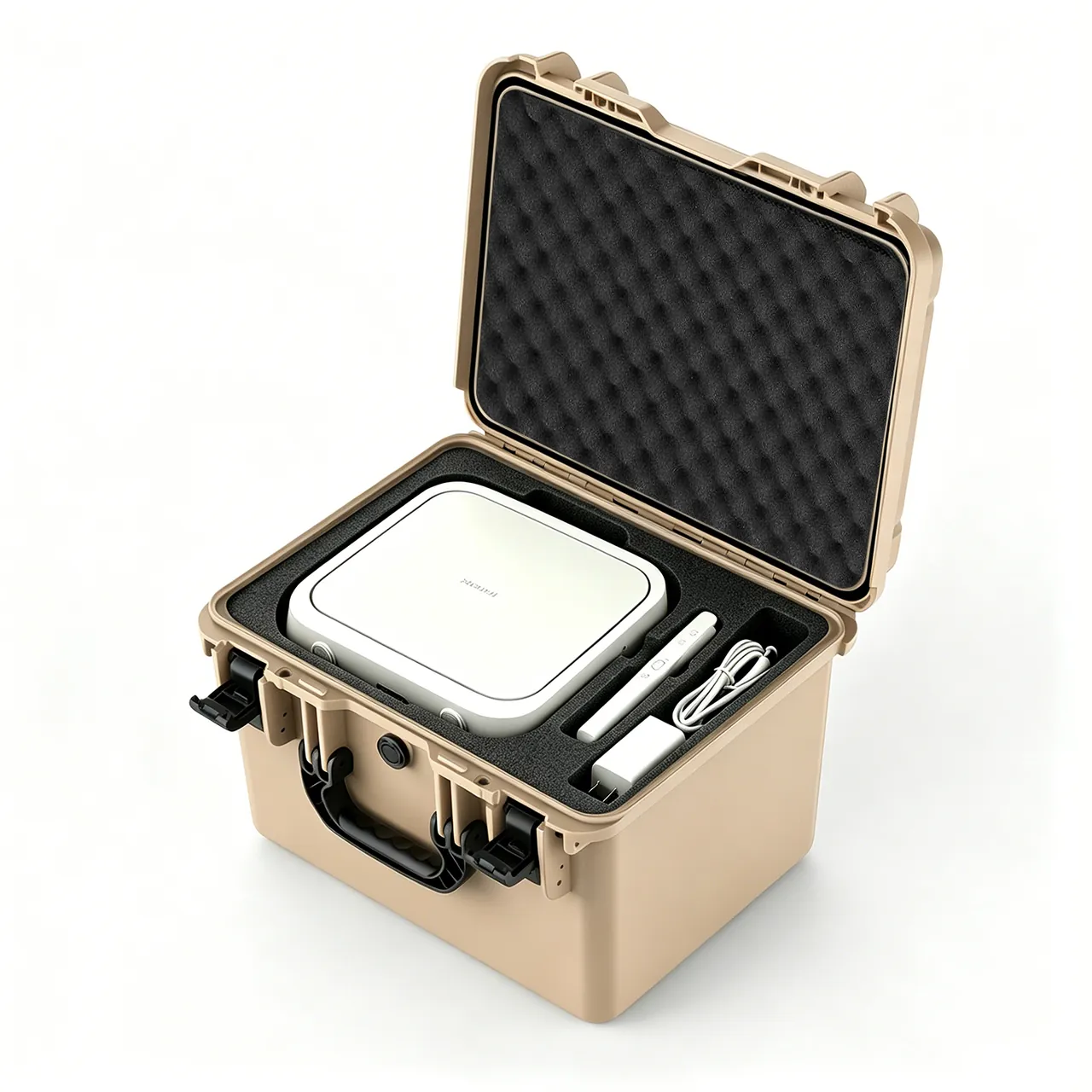
12. Sea Export, Returnable Re-Use and OEM/ODM Customisation
Five key variables in sea export. First, transit takes 30 to 45 days, so desiccant selection and quantity must be calculated from internal volume and duration. Second, the day-night temperature swing inside a container drives condensation, so a pressure equalisation valve is advisable so the case does not repeatedly inhale moisture. Third, deck carriage and open-air storage expose metal hinges, latches and handles to salt fog, so these need a higher corrosion class. Fourth, stacking layers at sea are usually higher, so compressive strength must be calculated for the worst-case stack. Fifth, export wooden packaging must meet ISPM 15 fumigation or heat treatment requirements; a plastic case avoids this issue but must still satisfy the destination market's environmental requirements for plastic packaging. Finally, sea freight usually connects to local truck delivery, and that last short leg often produces the most severe handling shock.
Returnable re-use and criteria. HVAC projects commonly recycle packaging after installation. Re-use demands more of a case than first shipment, because the case has already been through one transport cycle and both gaskets and linings have aged. Check five items before reuse: shell cracks or deformation, especially floor and corners; gasket hardening, cracking or permanent set; latch and hinge ability to close and carry load; lining collapse, fracture or missing guard panels; and castor and handle wear. Replace any failed item before reuse. Maintaining a log of case number, cycle count and inspection records is the lowest-cost and most direct management method available.
OEM/ODM points. HVAC cases are a high-variation, fragmented-batch category, so the procurement strategy should be built around standardised cases with customised linings: cover most models with three to five standard case sizes, then adapt specific models through custom linings, which amortises tooling cost. See custom case mould cost analysis. Evaluate suppliers across five dimensions: engineering capability, meaning the ability to issue an insert proposal from 3D data and run a trial fit; materials and process, covering foam density batch consistency and gasket cross-section and hardness; test capability, covering vibration, drop, stacking and water-ingress records; delivery and capacity, including peak-season flexibility; and quality system, including inspection rules and non-conforming material handling, using the sampling practice described in custom case acceptance and AQL.
Enquiry checklist. A practical enquiry should include the machine model and 3D data, component weight and machine centre of gravity, transport mode and route, number of re-use cycles, storage environment, target IP rating, test requirements, marking requirements, annual volume and delivery cadence. General guidance on evaluating factories is available in how to choose a protective case OEM factory.
JUNZHJIA normally works in the following sequence for HVAC equipment cases: accept 3D data or take a physical impression, issue a zoned insert proposal and case configuration recommendation, confirm the first article by trial fitting, then move to volume production with batch inspection and supporting test documentation. For long-term customers, a model archive is maintained so repeat orders reuse the approved design.
Frequently Asked Questions
Q: For whole-machine HVAC shipment, does the compressor need its own insert?
A: Yes, but the design must distinguish between two levels of restraint. Whole-machine restraint keeps the unit from moving relative to the case, achieved with load blocks, limit blocks and a top pressure block. Component restraint keeps the compressor from moving relative to the frame and prevents the piping from taking additional vibration, which requires second-stage damping at the compressor feet and clearance around the ports. Whole-machine restraint without component restraint is the classic "looks secure, fails in practice" scheme: the machine is fixed in place, but transport vibration still reaches the compressor piping through the frame and eventually produces fatigue cracking at welds. Mark the compressor's centre of gravity, port orientation and permitted tilt angle at the design stage and use them to set the damping layer thickness and limit block positions. For units above 200 kg, also check lifting points and forklift pockets so that a site lift does not tilt the unit beyond limits.
Q: Why is ordinary bubble wrap not recommended for coil fins?
A: Bubble wrap cushions point impact but cannot resist surface pressure, and it carries two specific problems for fins. First, its load path is localised at the bubble contact points, so under stacking or vibration the pressure concentrates there and still produces local collapse. Second, some bubble films contain migratable constituents that can affect the hydrophilic coating on aluminium fins or leave residue, and the high temperature and humidity of sea freight make this worse. The better approach is a rigid guard panel plus a soft separator layer, where the panel carries and distributes the surface load and the separator only prevents the panel from scuffing the fins. Panel area should be close to the coil face area to avoid edge stress concentration from a small panel. If strapping is unavoidable outside the coil, use wide webbing with corner protectors, never cord or narrow banding across the fin area. When inspecting on arrival, look for a large patch of fins deformed in a consistent direction, since that pattern points to surface pressure rather than ordinary impact.
Q: If a compressor leaks refrigerant after transit, how is responsibility determined?
A: The answer depends on the evidence chain rather than subsequent deduction. Keep records at both the packing and arrival stages. Packing-stage records should cover the pre-packing leak test result, the port capping method and photographs, the damping and restraint scheme, the completed packing photographs, and whether a tilt-limit indicator was fitted. Arrival-stage records should cover case exterior condition including drop marks, deformation, water ingress traces and seal integrity; tilt indicator status; visual and leak detection results at compressor ports and welds; and whether any secondary handling occurred after opening. With both ends documented, three scenarios can be distinguished: transport shock, where the case shows clear drop marks or the tilt indicator has triggered; packaging design weakness, where there are no external marks yet a weld has cracked, which normally points to cumulative vibration; and handling damage, where the port shows clear external force marks. The HVAC industry generally uses a pre-shipment transport test to expose the second category in advance, which is the most effective preventive measure available.
Q: Can a deformed fan impeller be straightened on site?
A: Generally no. Centrifugal fan impellers are thin-plate pressings or weldments, and straightening is a plastic deformation operation that introduces residual stress and cannot reliably preserve the relative position of each blade. Even if the appearance is restored, dynamic balance has usually changed, and running vibration and noise can end up worse than before, accelerating bearing wear. The correct response is to return the impeller to the factory for dynamic balancing or to replace it. This also shows why fan protection must focus on prevention: give the impeller its own cavity so it touches no rigid surface, provide axial restraint so the bearing does not take axial shock, and keep loose metal parts out of the case so they cannot rub the blades under vibration. For whole-machine shipment, first fix the fan's relative position inside the machine with profile sections, then restrain the machine inside the case. When inspecting on arrival, rotate the impeller slowly by hand to check for rubbing, and record baseline noise for later comparison.
Q: Does an HVAC equipment case need to be IP67?
A: It depends on exposure, and raising the number by default is not necessary. For domestic road transport with covered storage, IP54 to IP65 is usually sufficient. For sea freight, open-air storage, rainy or high-salt-fog regions, IP67 is advisable. Two points deserve emphasis. First, IP67 only guarantees that external water does not enter; it does not prevent internal condensation, and the day-night temperature swing on a sea crossing will produce visible condensation inside a sealed case, which is particularly harmful for equipment containing control boards and terminal boxes, making desiccant and a humidity indicator card close to mandatory. Second, a higher sealing level means a greater pressure differential across temperature changes, which makes the case harder to open and can distort the gasket, in which case a pressure equalisation valve is more effective than a higher IP number. Another practical consideration is weight: higher IP cases usually use heavier gaskets and stiffer closures, which raises handling effort on site. The correct approach is sealing, desiccant and pressure equalisation in combination, matched to the actual route rather than to a specification sheet.
Q: What extra requirements apply to HVAC equipment shipped with refrigerant or a nitrogen holding charge?
A: The first step is to establish the compliance boundary rather than judge it internally. Whether equipment constitutes dangerous goods and which transport regulations apply must be determined by a qualified body based on the nature of the goods, the pressure and the volume, and packaging and marking must align with the relevant compliance documents. This article draws no conclusion on specific classification. What can be stated is that pressure-vessel characteristics bring three packaging implications. First, capping and sealing must be reliable, using dedicated plugs and confirming per procedure. Second, the case should contain oil-absorbent or adsorbent material to handle an unexpected leak. Third, labelling must be clear, covering centre of gravity, attitude, rain protection and any necessary transport warnings. For export, note destination-market declaration and recovery requirements for refrigerant-containing equipment, and ensure packaging information matches the accompanying documents. Raise the question of pressure and refrigerant charge at the enquiry stage so that adsorbent material and warning labels can be designed in from the start.
Q: One-way export packaging or returnable cases, which is more economical?
A: Compare total cost of ownership rather than unit price. One-way packaging is assessed on unit cost and suits situations where the equipment is installed on arrival and the packaging is not recovered, for example a site with no storage or an international project with no return channel. Returnable cases should be assessed as unit price divided by cycle count plus maintenance cost per trip, and suit OEM internal transfers, repeated shipments by rental operators, and repair returns. Empirically, once cycle count exceeds three to five trips, returnable cases usually begin to show a cost advantage, but only if the case is genuinely maintainable: gaskets, castors and desiccant replaceable, and the lining replaceable on its own. If the gasket cannot be replaced and the case must be scrapped once the lining collapses, then "returnable" is nominal only. Clarify three questions during selection: who recovers and stores the cases, how many cycles are expected, and whether wear parts can be purchased separately. The answers often determine final cost more than the quoted case price.
Q: Besides vibration testing, what else should HVAC packaging validation include?
A: Use a combination of physical testing and functional checks rather than relying on appearance. Physical testing commonly covers random vibration, shock and drop, stacking, and temperature-humidity cycling, with salt fog and water ingress added for sea routes. Candidate standards include the ISTA series, GB/T 4857, ASTM D4169 distribution cycles, or environmental test methods referenced from MIL-STD-810H, noting that referencing its methods does not imply military certification. The functional check is what distinguishes HVAC equipment from general machinery: after vibration testing, verify piping leak tightness, check welds for seepage, rotate the fan to confirm no rubbing, inspect coils for fin collapse, and confirm control box insulation. The reason is that most HVAC damage is hidden, with an intact exterior concealing micro-cracks in piping or slight impeller deformation. Judging acceptance on functional criteria is what actually intercepts risk. Write the test items, standard numbers, sample quantities, functional checks and acceptance criteria into the contract technical annex, along with responsibility for rectification and retesting if the result fails.
Conclusion and Further Reading
The essence of HVAC transport protection is not wrapping the machine. It is solving three different physical problems separately: compressor vibration, fan deformation and coil compression. Because all three coexist in one machine, the packaging scheme must be capable of zoning: rigid structure carries weight, damping structure isolates vibration, and guard panels distribute surface load, each doing its own job. Treating the coil as a load-bearing member, or expecting one uniform foam layer to solve everything, are the two most common design errors in HVAC packaging.
The implementation path compresses into four steps: define the transport route and environment, classify which components bear load, which suffer vibration and which suffer compression, design case and lining by zone, then close the loop with transport testing and functional checks. Doing those four steps substantially reduces the probability of equipment that arrives intact but runs abnormally. Where a zoned insert proposal and case configuration recommendation are needed for a specific machine model, provide the 3D data, machine centre of gravity and transport mode to JUNZHJIA, which will issue drawings against the model and arrange first-article trial fitting.
Further Reading