

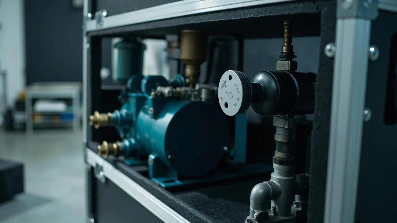
An air compressor parts case exists to do one job well: keep the air-end, inlet valve group, oil separator, coolers and control modules separated, immobilised and dry while a dismantled compressor travels across provinces or across oceans, so that assembly clearances and internal cleanliness survive the journey intact. A parts case is not judged by how thick its walls are, but by whether it solves three problems at once — rust on the air-end, contamination on valve sealing faces, and vibration plus static damage to electronics. Miss any one of the three and the cost of a factory rework or an on-site flush will dwarf the price of the case itself.
The failure stories repeat themselves. An air-end shipped bare arrives in a humid coastal warehouse three weeks later with surface rust already blooming on the rotor. An inlet valve packed loose beside bolts takes a dent on its sealing face and has to be lapped on site. A variable-frequency drive stacked in the same cavity absorbs continuous low-frequency vibration and reports a DC bus fault on first power-up. None of these losses are unavoidable — they are all designed out by a properly engineered case. This guide works through four tracks: components, materials, testing and acceptance, and ends with a specification you can put straight onto a drawing.
Table of Contents
- Why Compressor Parts Need Dedicated Cases
- The Air-End: Rust Control Comes First
- Valve Groups and Inlet Valves: Sealing Faces Must Stay Clean
- Oil Separators and Filter Elements: Crush and Moisture
- Coolers and Piping: Fins Are the Weakest Link
- VFDs and Control Boards: Vibration Plus Static
- Case Selection: From IK Impact Rating to IP67 Sealing
- Custom Inserts: EVA Cavities and Load-Bearing Layers
- Rust and Moisture Control: VCI Film With Desiccant
- Transport Testing: ISTA, GB/T 4857 and ASTM D4169
- Shipping Documents and Compliance Labels
- OEM/ODM Customisation Workflow and Sampling
- Incoming Inspection: AQL Sampling and Unpacking Checklist
- Frequently Asked Questions
- Conclusion and Further Reading
Why Compressor Parts Need Dedicated Cases
When a compressor ships as a complete unit, the factory only has to strap it to a pallet. The moment components enter the spare-parts channel, a regional service centre, or a rebuild-and-return flow, the air-end and valve groups come off the frame and each becomes a bare part.
When that happens, three load paths disappear at once: the rigidity formerly supplied by the machine frame, the positional relationships formerly supplied by the built-in piping, and the oil film formerly maintained by operating temperature. Every component degrades into an unprotected object.
The resulting risks fall into four groups, and sensitivity varies sharply between them.
| Component group | Primary risk | Secondary risk | Recommended protection |
|---|---|---|---|
| --- | --- | --- | --- |
| Air-end (screw or scroll) | Internal bore rust | Rotor impact, axial load on shaft | Internal rust-preventive oil + VCI film + vertical restraint |
| Inlet valve / minimum pressure valve | Sealing face denting | Embedded debris, surface staining | Face caps + dedicated locating cavity |
| Oil separator / filter elements | Media crushing | Moisture uptake, static dust attraction | Keep factory packaging + desiccant |
| Plate-fin cooler | Fin deformation | Nozzle distortion, residual water | Fins facing up + edge rail protection |
| VFD / control board | Low-frequency fatigue | ESD damage, loose terminals | ESD bag + suspended foam retention |
This table is only the starting point for the internal layout. What actually determines success is whether restraint strength is allocated according to risk tier. Packing every component into one large cavity and filling it with foam looks convenient, but in practice heavy parts crush light ones while light ones fail to restrain heavy ones.
Export batches add two more constraints: phytosanitary requirements for wooden packaging, and the humidity differential between origin and destination. If the destination port sits in a hot, humid region, relative humidity inside the case must be driven below 50 percent at packing and held below 60 percent by desiccant. The treatment of temperature and humidity conditions is set out in the guidance on export wooden packaging and transport packaging practice.
Note one complication specific to air-ends. If a compressor has run on a test bench before dispatch, the internal cavity inevitably retains lubricant and oil mist. That film is simultaneously a protective layer and a contamination source: it blocks water vapour, but once case temperature cycles across the dew point, condensed water becomes trapped beneath the film and sits against the metal for weeks, producing pitting. Humidity control for air-ends is therefore stricter than for ordinary machined parts.
The Air-End: Rust Control Comes First
The air-end carries the highest value and the highest rust risk in the whole shipment. Rotor tolerances on screw and scroll air-ends are typically measured in microns. Once visible rust appears, the practical fix is disassembly, polishing and re-shimming — a cost approaching replacement.
Rust prevention takes three steps. Skipping any one leaves a hidden failure.
Step one is preservation. Immediately after removal, charge the rotor cavity, bearing housings and shaft seal area with the same lubricant grade used in operation, then bar the rotor over several revolutions by hand so the film spreads evenly. If a dedicated preservative oil is used instead of operating oil, record the grade and flush it out completely before reassembly — mixing two incompatible oils produces varnish.
Step two is vapour-phase protection. Wrap the air-end housing in VCI film. The corrosion inhibitor released inside the wrap adsorbs as a monomolecular layer on metal surfaces. VCI depends on enclosure; a loose wrap lets the protective atmosphere escape. Where the shaft end is exposed, fit preservative paper plus a sleeve so the journal never contacts the insert directly.
Step three is attitude control. The air-end should travel in the same orientation it uses in service — vertical, or as specified by the original manufacturer. Laying it on its side puts rotor dead weight onto the bearing races, and sustained vibration can brindell those races. If side-lay is unavoidable because of case height, add a formed support block adjacent to the bearing housing to transfer that load into the case structure.
Insert geometry directly affects rust performance. When using custom EVA cavity tooling, the cavity floor should be a contoured surface that matches the air-end base rather than a plain rectangular cut-out. A contoured floor spreads contact across the housing ribs, avoiding stress concentration on thin walls. If the air-end has protruding oil ports, the cavity must be relieved at those points instead of relying on compressed foam to push back.
Valve Groups and Inlet Valves: Sealing Faces Must Stay Clean
Inlet valve assemblies, minimum pressure valves, thermostatic valves and oil stop valves fail in the field for two reasons: the sealing face and the spool guiding surface.
Sealing face failure is insidious. A metal-to-metal hard seal can withstand very high pressure once assembled, but a single grain of sand or a metal chip trapped in transit creates a micro-leak. Such leaks are usually invisible on visual inspection and only surface after operating hours as pressure that will not hold or oil migrating across circuits. Tracing them is expensive. Valve groups must therefore be physically isolated from tools, fasteners and paper documents inside the case.
Spool guiding surfaces fail through impact. The clearance between spool and body is often measured in tens of microns, so one over-spec lateral knock can jam the spool. Countermeasures are protective caps on both ends plus a dedicated cavity providing radial restraint. Never wrap a valve in bubble film and leave it free — bubble film resists surface scuffing but does nothing to constrain displacement.
Humidity effects on valves are consistently underestimated. A carbon steel body in an environment above 65 percent relative humidity with temperature cycling can show early corrosion within two weeks. Stainless bodies resist this, but where a stainless flange mates against a carbon steel one there is a galvanic couple to manage. Avoid leaving stainless components pressed against damp insert surfaces alongside carbon steel parts for extended periods.
A practical technique is assembly-level packing: pre-assemble the valves, pipes, gaskets and bolts of one functional circuit onto a sub-tray in installation order, then place the whole sub-tray in a foam cavity. This cuts on-site part-hunting time and prevents individual valves from migrating. Similar reasoning for industrial fluid-handling hardware appears in the selection logic for pump and valve parts cases.

Oil Separators and Filter Elements: Crush and Moisture
Oil separators, air filter elements, oil filters and precision filter cartridges are the classic low-value, high-sensitivity category. They do not fail by breaking; they fail by having performance quietly altered.
Media crushing is the most common problem. Pleated filter media holds its shape through the differential pressure across the pleats. Stack more weight on top than the media allows and the pleats deform permanently: filtration area drops, differential pressure rises. As a rule, filter elements should not be stacked beyond the layer count stated in the factory packaging, and they must never be used as packing material under other parts. If space forces stacking, insert a rigid divider between layers so the load goes into the end caps rather than the media.
Moisture uptake follows. Filter paper loses strength once it contacts water, and even sealed packaging will admit moisture through micro-leakage over long humid exposure. Place a 5 to 10 gram desiccant sachet in each filter sub-cavity and affix a humidity indicator card inside the case; replace the desiccant above 60 percent RH.
Static attraction is the third failure mode, mainly affecting elements for oil-free compressors in high-cleanliness service. Media rubbing against the insert generates static charge, which then attracts airborne dust. For oil-free machines serving medical, food or electronics duty, seal elements in ESD bags and choose insert materials with controlled surface resistivity.
Oil separators have an additional constraint. Their internal glass-fibre coalescing layer is highly sensitive to both oil contamination and water. Before packing, plug both the oil inlet and outlet, then cover the plugs with dust caps so no case dust can enter.
Field rule of thumb: standard industrial compressor filter elements tolerate up to three stacked layers; oil-free elements should be limited to two layers and individually bagged.
Coolers and Piping: Fins Are the Weakest Link
Plate-fin aftercoolers, oil coolers and intercoolers share a profile: large volume, uneven weight distribution, and a fragile heat-transfer surface. On a mid-size screw compressor, fin height is often 2 to 4 mm with roughly 2 mm spacing, which means any lateral rubbing flattens fins over a large area.
Three points govern the design.
First, fin orientation. Fin surfaces must face upward or toward a non-rubbing direction inside the case. Fins must never be pressed directly against the insert and then rubbed by vibration. In practice, cut shallow reliefs in the insert and let the cooler nozzles and frame carry the load, leaving the fin face suspended.
Second, edge rails. Add rails or corner blocks at the four corners and at nozzle penetrations, converting point loads into line loads. Rail material should be slightly softer than the cooler body to avoid hard-on-hard contact.
Third, internal draining. Drain and blow out water circuits before packing — this is mandatory for export. Residual water freezing in cold transit splits tube bundles; residual water in hot humid regions corrodes tube interiors. Fit plugs after draining and add a moisture-absorbing sachet to the case.
Piping components concentrate risk at flange faces and threaded ports. Flange faces get blind plates or plastic caps; threaded ports get plastic thread protectors; pre-bent copper or aluminium lines must be fixed to dedicated brackets to prevent secondary bending that thins the wall.
Cooler and piping layout also shifts the case centre of gravity. A heavy water-cooled cooler belongs at the bottom of the case near the wheel axle line; a high centre of gravity makes the case unstable in transit. This mirrors the centre-of-gravity discipline used for pressure vessel component cases.
VFDs and Control Boards: Vibration Plus Static
Electronic components now represent a growing share of compressor spare parts, and their failures rarely show as visible damage — they show up as power-up faults.
Vibration fatigue is the dominant mechanism. A variable-frequency drive contains cantilever structures such as electrolytic capacitors, terminal blocks and heat-sink screws. Under sustained 5 to 30 Hz vibration these loosen or develop fatigue cracks at their leads. Bubble film attenuates high-frequency shock but does little against low-frequency vibration. The correct approach is semi-suspension: support the unit from below on 45 to 60 kg/m³ foam, leave a 3 to 5 mm gap on all sides, and apply no downward pressure on top so the heat sink is not crushed.
ESD damage is the second category. Control boards, I/O modules and encoder interfaces are extremely static-sensitive. Bag them in shielding bags, fold and tape the opening, and do not vacuum-seal. Cap all exposed pins. Never place unsealed loose foam beads in the same cavity, since friction generates and accumulates charge.
Terminal protection is routinely overlooked. Vibration can loosen terminal screws and can fray conductors that swing back and forth. Photograph the wiring before disconnecting, cap every terminal afterwards, and bundle multi-core harnesses with ties labelled by circuit.
| Electronic item | ESD sensitivity | Vibration sensitivity | Protection priority |
|---|---|---|---|
| --- | --- | --- | --- |
| VFD unit | Medium | High | ESD bag + suspended foam + clearance above heat sink |
| Main control / I-O board | High | Medium | Shielding bag + dovetail slot or flat restraint |
| HMI touch panel | High | High | Rigid screen cover + separate cavity |
| Pressure / temperature sensors | Medium | Medium | Keep factory packaging + probe sleeve |
| Cables and harnesses | Low | Low | Bundled with ties, kept out of heavy-part cavities |
Where an operator panel must travel with the shipment, consider temperature. Liquid crystal displays can suffer irreversible damage below minus 20 degrees Celsius. Cold-climate shipments should use insulated cases, or the panel should be removed and packed separately with thermal protection.
Case Selection: From IK Impact Rating to IP67 Sealing
The case shell is a structural component whose job is to protect contents across four scenarios: drop, stacking, rain and dust.
Material choice depends on unit weight, transport mode and the customer's cost sensitivity.
| Shell material | Typical weight range | Strengths | Limitations |
|---|---|---|---|
| --- | --- | --- | --- |
| Copolymer polypropylene injection moulded | Up to 60 kg | Good impact resistance, easy sealing, wheel options | High tooling cost at large sizes |
| Rotomoulded HDPE | 60 to 200 kg | Low-temperature impact, large sizes | Uneven wall thickness, moderate precision |
| Aluminium-magnesium frame | 30 to 150 kg | High rigidity, serviceable, heat resistant | High cost, seal depends on gasket |
| Plywood composite | 100 to 500 kg | Low cost, easy custom sizing | Poor water resistance, fumigation required |
| Steel frame with panels | Above 300 kg | Highest load capacity, craneable | Heavy, needs corrosion protection |
Ingress protection. Compressor parts are oily and metallic, so dust and splash resistance is the baseline. An IP67 protective case resists short-term immersion and suits sea freight with open-yard transfer; IP65 is generally sufficient for domestic road transport under tarpaulin. Note that IP67 depends entirely on gasket continuity and even latch compression. Any local distortion downgrades the whole case. Material trade-offs across temperature range and oil resistance are compared in the guide to case sealing materials.
Pressure equalisation is easily missed. A well-sealed case can see a pressure differential above 30 kPa during air freight or high-altitude road transport, which makes the case hard to open or deforms the gasket. The fix is a case pressure equalisation valve: it allows slow gas exchange while blocking liquid water and dust, and is standard fitment for air-freighted batches.
Latches and hinges determine service life. Compressor spare-parts cases are often specified for five years of reuse. Choose latches with metal cores in the moulding, and stainless hinge pins. The fatigue life discussion in toolbox hinge, latch and seal construction is a useful selection reference.
Custom Inserts: EVA Cavities and Load-Bearing Layers
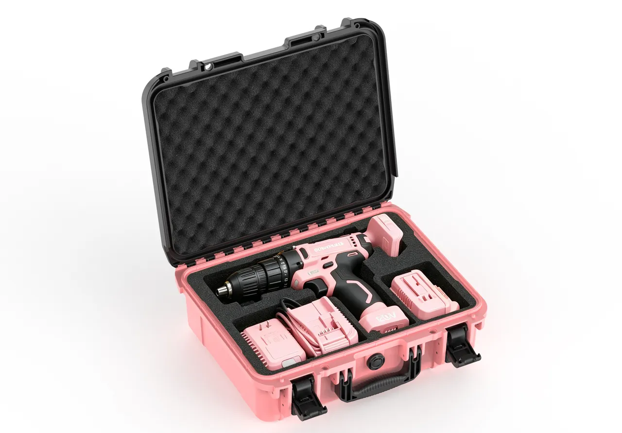
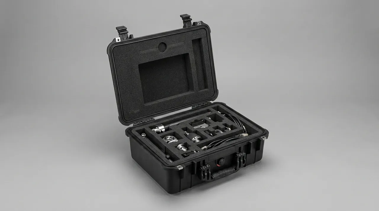
The insert is where a compressor parts case earns its value. The shell decides whether external impact is survived; the insert decides whether internal components damage each other.
EVA and PE foams dominate. EVA offers better resilience and moulding precision, making it suitable for complex contoured cavities. PE foam resists compression set better and suits base support layers. The standard build is a three-layer stack: a 30 to 50 mm high-density PE base for support, a 30 to 40 mm EVA middle layer for contour location, and a 20 to 30 mm medium-density top pad for restraint.
Design inputs required for an insert are: dimensions and weight of each component, fragility (the maximum acceleration it tolerates without damage), load-bearing face positions, and protrusion locations. Heavy items such as air-ends are typically assessed at 40 to 60 G fragility; electronics such as VFDs sit nearer 25 to 35 G. Fragility is what lets you calculate the required foam thickness and bearing area.
Layering is the standard technique for heavy cases. Split the case into upper and lower levels: heavy air-end and coolers below, valve groups, filter elements and electronics above, with a structural divider between them — carrying load through the divider, not through foam. The divider must rest on ledges moulded into the case side walls, never on foam friction alone. Then even if upper-layer parts shift under vibration, their weight never lands on the air-end below.
Cavity tolerances need allowance. EVA is elastic, and a cavity cut to zero clearance against the component means the part must be forced in; over time the cavity walls fatigue and loosen. A practical rule is 1 to 2 mm clearance per side against the component outline, with 3 to 5 mm foam shims on the cavity walls for fine adjustment. This holds the part without marring its surface.
Rust and Moisture Control: VCI Film With Desiccant
Rust and moisture control is what separates a compressor parts case from a generic equipment case.
VCI vapour-phase protection suits metal parts in an enclosed space. VCI film, VCI paper and VCI emitter devices all work, subject to three conditions. First, VCI needs reasonable enclosure — the higher the case sealing grade, the better it performs. Second, compatibility varies by metal: copper, aluminium and zinc-plated parts need compatible formulations, since amine-based inhibitors can attack copper. Third, VCI has a finite protection window, typically 12 to 24 months, so longer shipments need replenishment emitters.
Desiccant selection depends on whether the application is static or dynamic. Static shipments that are not reopened in transit can use bagged silica gel; long-term storage or high-humidity destinations call for montmorillonite or molecular sieve. Dosage should not be guessed. A working field estimate is 1 to 2 kg of silica gel per cubic metre of free case volume, adjusted for transit duration and the moisture-vapour transmission rate of the packaging.
Humidity indication is mandatory. Affix an indicator card to the insert at packing so it is visible the instant the case opens. The usual acceptance threshold is 60 percent RH: below is pass, above requires desiccant replacement and a corrosion re-check on metal parts.
Direct-contact protection is the final layer. Every exposed metal surface that could touch the insert or another component should be separated by preservative paper or film. Pay particular attention to dissimilar metals: a stainless screw pressed onto a carbon steel flange forms a galvanic couple in damp conditions, so an insulating washer belongs between them.
For export batches to Southeast Asia, the Middle East or South America, fit a reusable desiccant canister inside the case and print a bilingual instruction on the outside reading "reseal and replace desiccant after opening". This practice is also recommended for long-cycle sea freight in the general specification for IP-rated protective cases.
Transport Testing: ISTA, GB/T 4857 and ASTM D4169
Whether a protection design works is ultimately settled by test data. Three frameworks dominate for compressor parts cases, each with a different emphasis.
| Test framework | Scope | Typical procedures | Where it fits |
|---|---|---|---|
| --- | --- | --- | --- |
| ISTA series | Complete package | Drop, vibration, compression, concentrated impact | E-commerce and line-haul, internationally recognised |
| GB/T 4857 series | Complete package | Drop, stacking, vibration, water spray | Domestic sales and export documentation |
| ASTM D4169 | Assembled by distribution cycle | Multiple procedures selected by DC level | Large equipment, multimodal transport |
| MIL-STD-810H | Environmental suitability | Vibration, shock, temperature-humidity, salt fog | Harsh environments, not a military certification |
ISTA 3A and 3E suit single packages and typically specify drop, random vibration and compression. A compressor parts case shipped as a single unit under 70 kg can be designed to 3A intensity; palletised consolidations usually follow 3E or 2B.
GB/T 4857 is the most commonly cited basis domestically, and its stacking and vibration procedures are the most direct test of shell structural strength. Most customers require a third-party report to this standard as acceptance evidence; the procedure set is described in the transport packaging test method overview.
ASTM D4169 is valuable because it allocates intensity by distribution cycle. The same case travelling by courier, by less-than-truckload carrier, or inside a full container experiences entirely different stress spectra. D4169 requires the distribution cycle to be defined first, then procedures and intensities selected by DC level — much closer to reality than a fixed procedure list. Multimodal export batches are usually designed to D4169.
MIL-STD-810H vibration and shock methods are frequently cited as environmental suitability evidence. State clearly that MIL-STD-810H is applied here only as an environmental test method reference and does not indicate military certification. Where a customer has humidity or salt fog requirements, methods 507 (humidity) and 509 (salt fog) can be added as design references.
A workable sampling approach: during structural qualification, run one or two complete rounds of testing; in series production, sample critical items per batch according to the custom case acceptance and AQL standard. Drop and stacking tests are destructive and are normally not repeated per batch — instead, production quality is assured through structural consistency control.
Shipping Documents and Compliance Labels
For an export compressor parts case, the accompanying documents and case labelling are themselves part of delivered quality.
Recommended document set: packing list with part numbers, quantities and serial numbers; unpacking work instruction; component layout diagram; desiccant replacement instructions; inspection records and certificate of conformity; material declarations where applicable. For valve groups or pressure-containing components, provide the compliance declarations required by the destination market.
Case labels should carry: component name and model, gross and net weight, case dimensions, lifting and orientation marks (this way up, keep dry, maximum stacking), customer order number and case number. Export batches should use bilingual labelling or the destination language directly.
Label durability is often neglected. Inkjet printing fades in humid conditions. Use laminated or in-mould labels and apply them to two sides of the case so a single worn face does not render the shipment unidentifiable.
Wooden packaging must comply with ISPM 15 and carry the IPPC mark; engineered wood such as plywood is exempt. For metal-containing packages, avoid untreated solid wood as a direct-contact material, because wood moisture content influences internal case humidity.
OEM/ODM Customisation Workflow and Sampling
Compressor OEMs, regional agents and spare-parts distributors want different things. OEMs care about compatibility with existing packing lines and batch consistency. Agents care about model coverage and stock turnover. Distributors care about whether one case can serve several machine models.
A workable customisation workflow has five steps.
- Requirements capture: component list, 3D models or measured dimensions, weights, fragility requirements, transport route and destination market.
- Concept design: case form factor and opening method, insert layering, rust and moisture configuration, labelling scheme, with drawings and bill of materials issued.
- Prototype validation: build one first article, run a trial fit and a short-range vibration screening, confirm no component displacement, correct lid closure and even latch loading.
- Test confirmation: run full-case testing to ISTA or GB/T 4857 and issue the report.
- Production and first-article approval: freeze tooling and process parameters, complete first-article inspection, then release to volume.
Lead time is usually dominated by injection tooling, followed by insert cutting dies and sampling. If a customer can adopt an existing near-size shell, customisation reduces to a new insert, compressing lead time to a matter of weeks. This "standard shell plus custom insert" route is also recommended for low- to mid-volume buyers in the guide to choosing a case OEM factory.
For distributors needing their own branding, in-mould labels, screen printing and hot stamping are all available. The standard JUNZHJIA approach is to build insert libraries by machine family: one shell size serves a whole series, and only the insert and label change, balancing customisation against cost.
Incoming Inspection: AQL Sampling and Unpacking Checklist
Acceptance is what determines whether a problem is found inside the warranty window. Work through four steps: appearance, structure, sealing, contents.
Appearance: check for cracks, distortion and significant scratches; verify latches, hinges, wheels and telescopic handles; confirm labels are legible and complete.
Structure: load the empty case to its rated load and leave it 24 hours, then measure wall deflection; cycle the latches 50 times and confirm no binding.
Sealing: run the test appropriate to the IP rating — IP67 requires short-term immersion or an equivalent pressure test. Inspect the gasket for twisting, displacement from its groove, and compression marks.
Contents: this is the critical step for compressor parts cases, because most latent damage is only discovered here. Check the air-end shaft end for rust spots, bar the rotor over for smoothness, inspect valve sealing faces for dents and debris, check filter element end caps for distortion, measure fin deformation area on coolers, verify electronic terminals are tight, and read the humidity indicator card.
Sampling levels: critical items such as air-ends and VFDs should be inspected 100 percent; general parts follow AQL general inspection level II with an acceptance quality limit of 1.0 to 2.5. The sampling tables and decision rules are covered in custom case acceptance and AQL sampling.
Inspection records must retain photographs and measured data, especially for the three problem classes: corrosion, distortion and displacement. These records serve both as the basis for claims and as design input for the next batch of insert and rust-prevention revisions.
Frequently Asked Questions
Q: Should the air-end travel upright or on its side inside the case?
A: Upright, matching the installed orientation, is always preferred. Screw and scroll air-ends are designed to carry axial and radial loads through their bearings during operation. Laying the unit on its side puts rotor dead weight directly onto the bearing races, and sustained transport vibration can brindell those surfaces, degrading clearance and raising noise. If case height forces a side lay, add formed support blocks at the bearing housing positions so the weight transfers into the case structure, and fit soft pads on both sides of the journals so the bearings never see a concentrated load. Bar the rotor over by hand after packing, then repeat at destination and compare; any binding or abnormal resistance means the bearings should be inspected. For large air-ends, fit an acceleration recorder inside the case and read the peak at arrival as the decision input for whether the unit needs inspection before installation. Record the required orientation on the case label so warehouse staff do not reorient the case during secondary handling.
Q: Does VCI film affect copper and aluminium parts?
A: Yes, and this is the single most common misapplication. VCI inhibitors come in formulations for ferrous metals only, for non-ferrous metals, and as multi-metal grades. Formulations containing ammonia or amines can promote corrosion on copper and copper alloys, dulling surfaces and producing green verdigris. Compressor valve groups frequently contain copper spools, copper tubing and brass fittings, and some air-ends use copper bearing cages, so a multi-metal grade is mandatory. On aluminium, some VCI formulations cause surface discolouration under hot, humid conditions, so run a 72-hour accelerated check before committing. Note also that VCI protection windows typically run 12 to 24 months, so longer shipments need replenishment emitters, and components should move into a normal indoor storage environment immediately after unpacking. Remember that VCI cannot remove existing corrosion, only limit further attack, and it performs best in an enclosed volume, so the higher the case sealing grade the more reliable the result.
Q: Is IP67 sealing really necessary for a compressor parts case?
A: It depends on the transport route and storage conditions. If components travel in a full container, sit in an open port yard, or transfer between multiple modes, IP67 has clear value against short-term immersion and heavy rain. If the entire route is domestic road transport under tarpaulin with immediate warehousing on arrival, IP65 is usually sufficient and costs less while opening and closing more easily. Note that IP67 does not mean the case can be stored underwater long term, nor does it stop vapour transmission. For long storage, desiccant and VCI do the real work, not the shell rating. Also remember that IP67 depends on gasket integrity and even latch loading; once the gasket ages or the case rim distorts, the rating degrades, so sealing components need replacement on a rubber-life schedule. When specifying, base the rating on the worst-case leg of the journey and state the test method and acceptance criteria in the contract, so nothing is left to interpretation on arrival.
Q: How much desiccant should be used, and when does it need replacing?
A: Dosage depends on free case volume, the moisture barrier performance of the packaging, and transit duration. A working estimate is 1 to 2 kg of silica gel per cubic metre of free volume, doubled for high-humidity destinations or long sea voyages. If the case achieves IP67 sealing and the insert is closed-cell foam, the quantity can be reduced somewhat. The replacement criterion is the humidity indicator card: a reading below 60 percent RH at unpacking is a pass; at or above 60 percent requires desiccant replacement plus a corrosion re-check on metal parts. For spare parts held in long-term storage, use a reusable desiccant canister and print the replacement interval on the case so the end user does not inadvertently let moisture protection lapse. Bear in mind that desiccant is not a dehumidifier: it can only absorb vapour already present in the case and cannot offset continuous ingress, so sealing quality and drying parts before packing matter as much as the amount used.
Q: Is EVA or PE foam better for the insert?
A: They serve different purposes and are usually combined. EVA has better resilience, cuts into complex contoured cavities and has a fine surface that will not scratch components, making it ideal for the locating layer; its drawbacks are some permanent deformation under sustained compression and a higher cost than PE. PE foam resists compression set well, has low water absorption and costs less, making it suitable for base support and large-area cushioning, though its moulding precision is lower. A recommended stack is a 30 to 50 mm high-density PE base, a 30 to 40 mm EVA locating layer, and a 20 to 30 mm medium-density top pad. Where oil-bearing parts contact the insert, cover the EVA with an oil-resistant film so the foam does not soften and collapse after long-term oil absorption. If components will be loaded and unloaded repeatedly, bond wear-resistant material along the cavity lips too, since the lips wear first and loosened retention shows up as slight component movement.
Q: Can the air-end and valve groups share one layer?
A: Technically yes, subject to two conditions. First, a rigid divider must carry load between them, resting on ledges in the case side wall so the air-end weight never transfers to the valves through foam. Second, the valve groups need their own locating cavities and at least 20 mm of clearance from the air-end, so the small movements of the air-end under vibration cannot press against them. A layered arrangement is safer: heavy items such as the air-end and coolers below, valve groups, filter elements and electronics above. This lowers the centre of gravity, makes the loading sequence obvious, and allows different case groups to ship to different customers. If a single layer is unavoidable, add restraint blocks on all sides of the air-end so every degree of freedom is constrained, and keep at least 30 mm of clearance above the valve groups so a dropped accessory cannot strike a sealing face directly.
Q: What extra treatment is needed for shipment to high-humidity regions?
A: Focus on eliminating moisture sources and increasing cushioning margin. Blow metal surfaces dry before packing, and let the components equalise to ambient temperature before closing the case, so that a warm air-end cannot draw condensation onto its machined faces as it cools inside the closed case. Charge the air-end cavity with preservative oil and fit plugs, and drain and dry water-cooled circuits. Fit ample desiccant and an indicator card, and avoid open-cell foam on insert surfaces, because open-cell foam absorbs water and becomes a long-term vapour source. For the container itself, hang container desiccant bags, since a case cannot defend against humidity across an entire container. Unpack into a dry warehouse as soon as possible rather than leaving the case in an uncontrolled port shed. Where the customer's site cannot control humidity, keep the factory desiccant in place and inspect internal cavities before reassembly. Finally, plan the logistics window so the case is not left standing in an uncontrolled shed for weeks: a well-protected shipment can still corrode if it is parked in a monsoon climate with no handling.
Q: What test items should be included if a customer requests a test report?
A: It depends on the customer's acceptance system and destination market. For domestic sales and general export, a GB/T 4857 report covering stacking, vibration and drop or concentrated impact usually satisfies the requirement. For cross-border e-commerce or courier line-haul batches, add ISTA 3A or 3E. For multimodal transport, overweight items, or customers who have defined the distribution cycle, ASTM D4169 with the corresponding DC level is more persuasive. If a customer mentions a military standard, clarify in advance that MIL-STD-810H is applied here only as an environmental test method reference and does not indicate military certification, avoiding ambiguity later in the documentation. All reports should come from a third-party laboratory holding the appropriate accreditation. It is also worth attaching pre-test and post-test inspection records and photographs, because what the customer really wants to know is whether components deformed or shifted, not simply whether the package passed. Where the customer is a distributor rather than an end user, ask which market the goods are destined for, since acceptance expectations differ considerably between regions and specifying the right test basis up front avoids a re-test later.
Q: For a reusable parts case, what most affects service life?
A: In descending order of impact: latch and hinge fatigue, gasket ageing, and insert compression set. A latch opened once daily for five years sees nearly two thousand cycles, and an injection-moulded latch without a metal core will tend to crack at its stress concentrations. Gaskets harden and lose resilience under combined ultraviolet, ozone and oil exposure, typically requiring replacement every three to five years. Insert foam gradually compresses thinner under sustained load, leading to loose components, visible as parts that rock when the case is opened. A maintenance plan should therefore include cleaning and gasket inspection after each use, latch and hinge checks annually, and an insert replacement assessment every two years. Cleaning method matters as well: avoid aggressive solvents, which accelerate plastics ageing and swell gaskets. Keep a small stock of replacement gaskets and latches rather than ordering them after a failure, since a worn part is far cheaper to swap than a shipment is to replace. Followed consistently, this keeps effective case life in the eight to ten year range.
Conclusion and Further Reading
The design logic of a compressor parts case reduces to one principle: allocate protection by risk, not fill space by volume. The air-end rusts, so charge it with oil, wrap it in vapour-phase film and control its attitude. Valve groups contaminate, so cap them, locate them separately and isolate them from tools. Filter elements crush, so limit stacking, add dividers and use desiccant. Coolers dent, so face fins upward, add edge rails and drain water circuits. Electronics suffer from vibration and static, so suspend them on foam, bag them in shielding material and cap every terminal. Get those fundamentals right and the shell structure, sealing grade and test validation become meaningful rather than decorative.
On top of that, close the loop across moisture control, testing and acceptance. Control humidity and fit an indicator card at packing. Validate to ISTA or GB/T 4857 before shipping. Confirm item by item against a checklist at destination. Skip any one of those links and a single rework can erase everything spent on materials. JUNZHJIA maintains insert libraries, rust-prevention configurations and test documentation for compressor and refrigeration equipment parts cases, supporting OEM/ODM programmes, seals matched to specific machine models, and delivery of corresponding inspection documents.
Further Reading