

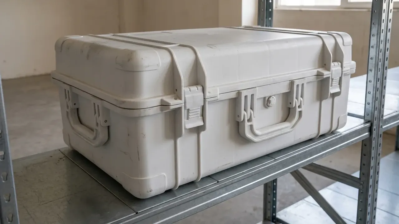
Quick answer: A Camera motorized slider & controller box holds wall inset under 0.75 mm after 20 min at 35 kPa, with a 92 mm rib grid and 94 percent rebound.
Table of contents
- Rib grid spacing of the Camera motorized slider & controller box
- Gap between the twin gasket grooves
- Wall inset after twenty minutes of vacuum
- Rebound measured after venting
- Grid setpoint for controller batches
- FAQ
1. Rib grid spacing of the Camera motorized slider & controller box
Air drawn out of the shell bows the wall inward, and the rib grid density with the gap between the two gasket grooves governs how far it springs back once pressure returns. The Camera motorized slider & controller box carries a square lattice of internal ribs at a nominal 92 mm pitch. Between a 610 x 425 x 235 mm outer envelope and a 545 x 360 x 170 mm cavity the shell keeps a 4.5 mm wall, and the ribs grow from that base. Open the pitch to 108 mm and the unsupported panel cups inward under suction first. JUNZHIJIA logs 92 mm as the nominal tier and moulds a sparse and a dense tier alongside it, all three from one material lot and one tool, with rib layout as the only variable.
A coordinate measuring machine samples the pitch at six stations, each within 1.5 mm of nominal. Pitch restrains in-plane stiffness while the 14 mm groove spacing restrains sideways slip at the mouth; both carry load on the vacuum rig, so the trial card lists them on one row. Either reading alone cannot predict the rebound.
| Grid tier | Measured pitch | Wall inset at 20 min |
|---|---|---|
| Sparse | 108 mm | 0.92 mm, reject |
| Nominal | 92 mm | 0.61 mm |
| Dense | 76 mm | 0.40 mm |
2. Gap between the twin gasket grooves
The Camera motorized slider & controller box cuts two seal grooves around the lid mouth, centres 14 mm apart; the outer line blocks seepage along the rim, the inner line holds the mismatch that appears as the lid closes. Squeeze the spacing to 10 mm and the strips fight for room; push it to 18 mm and the outer line sits too near the edge, where suction can roll its lip.
Before the Camera motorized slider & controller box goes onto the vacuum rig it runs 4000 empty open-close cycles, then the rig pulls 35 kPa. Four latches at 405 N each are checked in that pass, and any run with the lid not fully seated is dropped. Both the 6.3 kg empty and 16 kg loaded states are run, and the larger inset is kept.
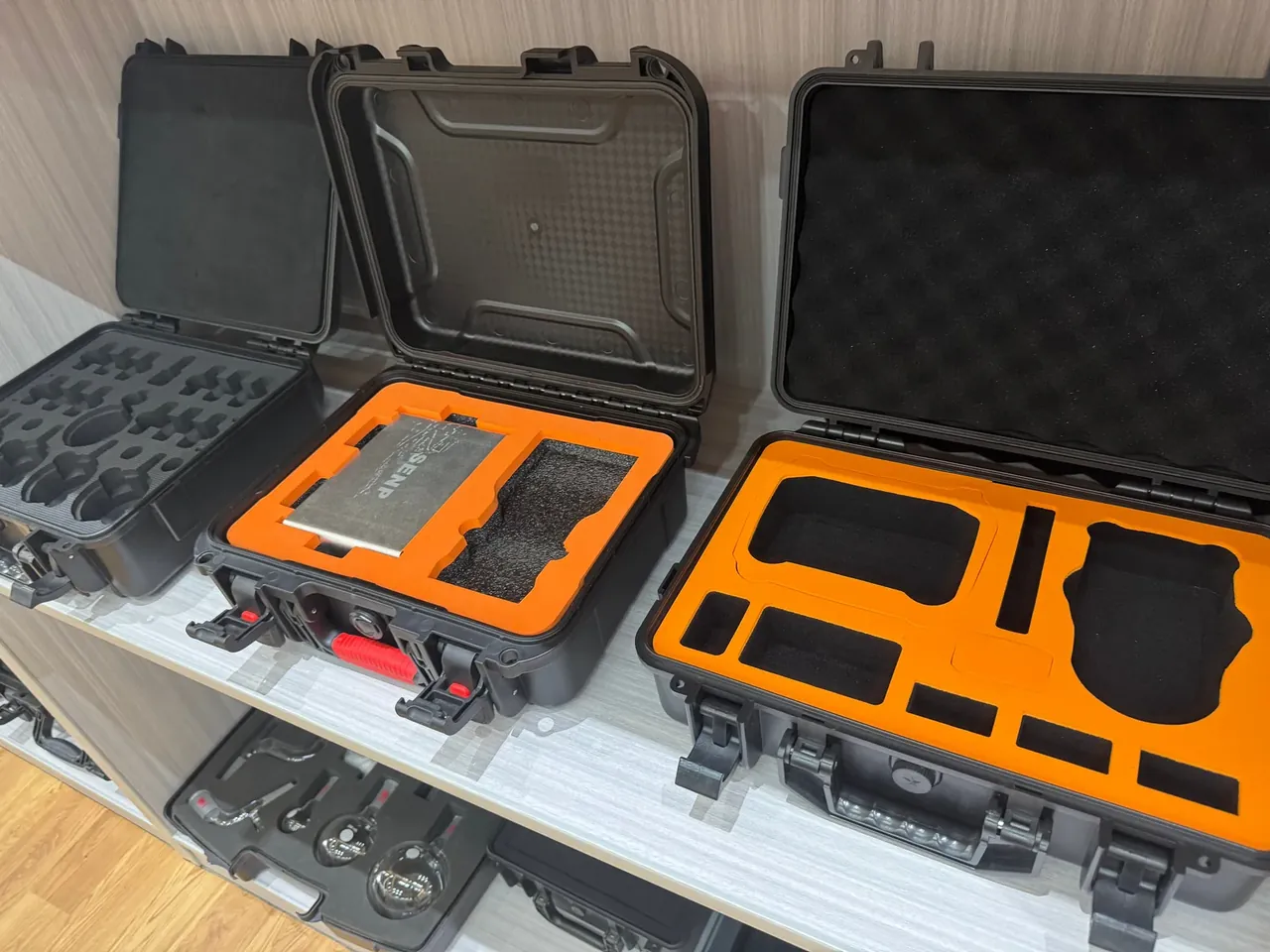
The mouth mating face is cross-checked against an IP66 spray, and the two gaskets at 20 percent compression are inspected in that round: if the pitch drifts, seepage shows at the mouth first and is read against the inset log. The spray judges only the mouth and never replaces the cell-centre remeasurement.
3. Wall inset after twenty minutes of vacuum
The Camera motorized slider & controller box reads cell-centre displacement in three windows: the rig holds 35 kPa for 20 min, and a dial indicator logs at 5 min, 10 min and 20 min. The ceiling is 0.75 mm, and the 20 min window works hardest as the wall creeps under sustained pressure. The fixture drifts about 0.02 mm at zero, so that offset is subtracted first. The largest value over the whole field is logged, and the indicator stand is clamped to the rig beam rather than the shell so tooling movement is not written down as inset.
| Hold period | Wall inset | Reading |
|---|---|---|
| 5 min | 0.22 mm | ramp up |
| 10 min | 0.48 mm | climbing |
| 20 min | 0.68 mm | setpoint |
0.68 mm still leaves room under 0.75 mm, and as long as the 10 min to 20 min climb stays under 0.20 mm the grid is judged able to carry the difference. The rig covers only the pumped-down side; rebound after venting is measured later, and the two readings are not merged.
4. Rebound measured after venting
The Camera motorized slider & controller box does not close the gauge the moment the valve opens; the shell rests 3 min before recovery is read, with rebound held at no less than 94 percent. If the inset recovers only nine tenths, the rest is treated as residual deformation traced to the rib root and moulding orientation. Venting rebound and hold inset are separate load paths, and every shell clears both.
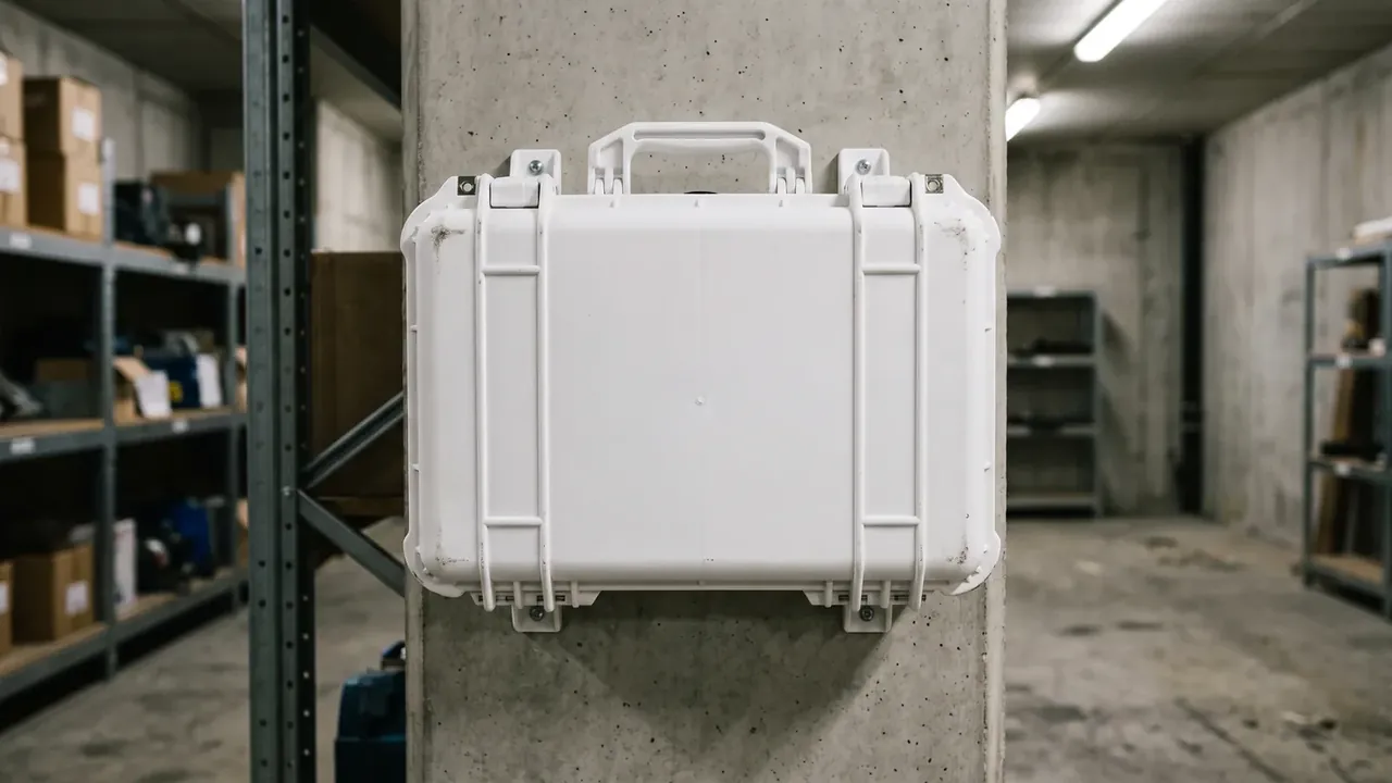
The Camera motorized slider & controller box ties the terminal inset, the 3 min recovery value and the rebound rate to one shell number, so the surface batch code maps only to its own rig data. The IP66 spray retest follows the rebound figures, checking whether the two gaskets have opened as the pitch moved. The same shell that finished 4000 cycles is pumped down once more, to confirm latching has not worn the springback out of the grid.
5. Grid setpoint for controller batches
Eight shells per batch are measured at the grid pitch for the Camera motorized slider & controller box: a reading 16 mm above the 92 mm nominal is a reject, and two such shells send the whole batch back for a tool correction, with no releasing the good ones alone.
Grid setpoint is fixed at the sparsest tier whose 20 min inset still stays within 0.75 mm; any sparser layout goes back for retooling as a batch. Widen it further and the 10 min to 20 min climb starts to rise. Mould temperature, hold duration and this line are written together into the process card by JUNZHIJIA, and any material or tool change adds one more full 20 min vacuum run.
The Camera motorized slider & controller box ties each shell's inset, rebound and reject verdict together, and the three inset bands below carry their own disposition so a recheck operator does not read the dense tier's spare margin as a blanket allowance. Kexin New Materials (Guangdong) Co., Ltd. files by shell number.
| Inset reading | Matching grid tier | Disposition |
|---|---|---|
| no more than 0.75 mm | nominal 92 mm | release |
| 0.75 to 0.90 mm | sparse 108 mm | remeasure pitch |
| above 0.90 mm | reject band | whole batch retool |
Conclusion
A 92 mm rib grid paired with a 14 mm twin-gasket gap lets the Camera motorized slider & controller box hold wall inset under 0.75 mm after 20 min of vacuum and keep venting rebound above 94 percent. Measured pitch, the three window curves and the reject line are logged as graded cards at JUNZHIJIA. A tool or material change adds one more 35 kPa hold; when specifying a case of this kind, ask first whether pitch and groove spacing come with figures that can be rechecked.
Related Reading
- Camera Equipment Case Guide: Hard Case Sizing, Foam Buffer and Moisture Control
- Camera Equipment Case Selection: Body, Lens and Accessory Zoning
- Broadcast and Film Equipment Cases: Large Payloads, Flight Schedules and Fast Turnarounds
- Choosing Pelican Alternative Cases: Spec Comparison and Pitfalls
Related Products
- 8 Series — Gun Cases; Military Equipment Cases; Camera Equipment Cases; Drone Cases; Watch Cases; Knife Cases; First Aid Cases; Electronics Equipment Cases
- WL8-2812 PP Gun Case — model WL8-2812
- All protective cases and toolboxes: 7 series, 158 models