

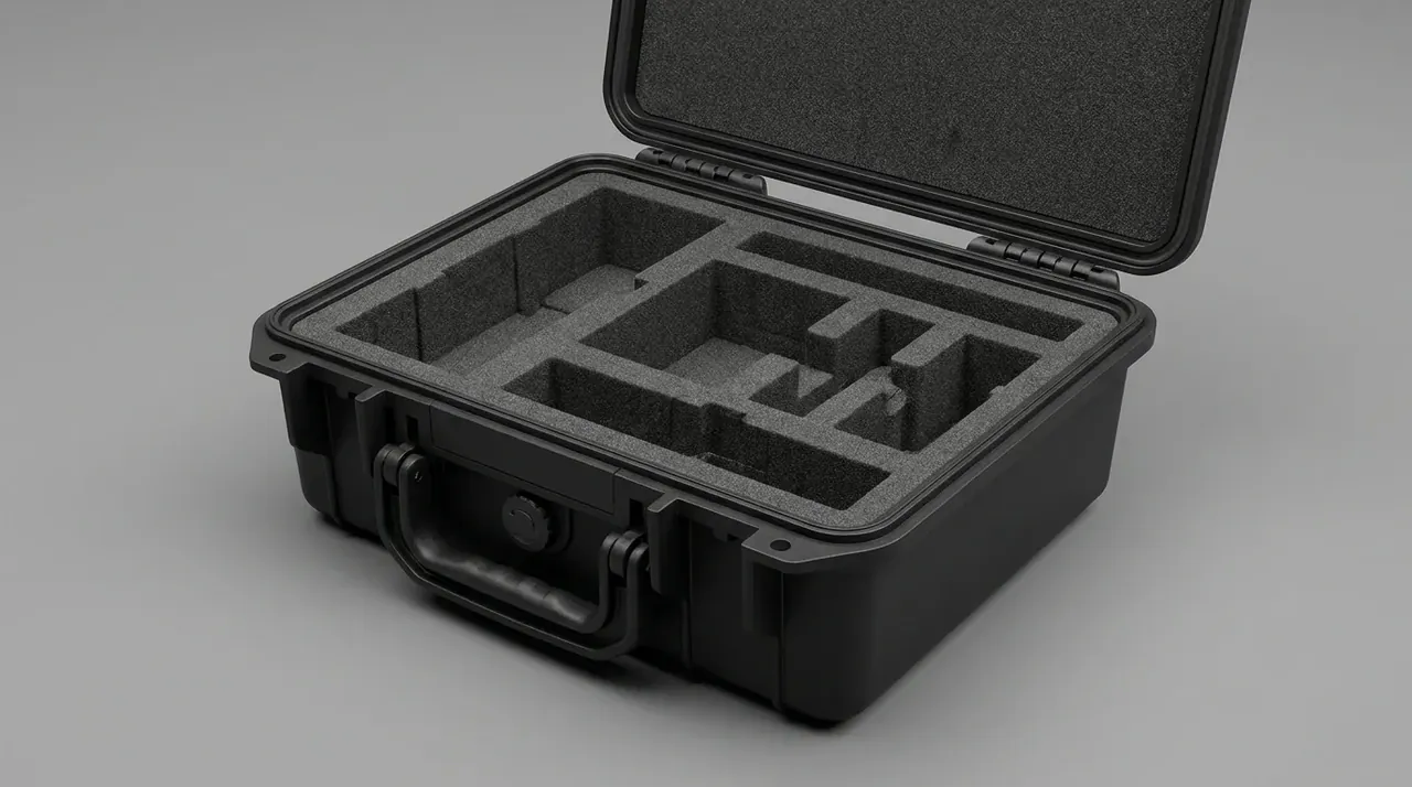
Quick answer: Case cutout sealing rests on how wide a sealing ring the wall can offer, not on the bore: a 20 mm hole in a 3 mm wall leaves 3 mm to clamp. A 46 mm flange, six M4 bolts at 1.2–1.5 N·m and a 3 mm pad move the leak path outside.
Table of contents
- What a cutout takes off the wall
- Flange clamping spreads load over six bolts
- How grooves and rings hold the bore
- When potting or rubber pads replace a flange
- Placement clearances and holding the rating
- FAQ
1. What a cutout takes off the wall
A monitoring project drilled a 20 mm cable port through one side wall, fitted a rubber grommet and ran a 30 minute rain test. The case took in 220 mL, and the water came through the bore, not the rim. The wall there measured 3.0 mm, the grommet covered under 3 mm of flat face, and it went solid after 0.4 mm of compression.
A cutout removes three things at once: wall thickness, sealing face width, and flatness around the bore. Lose one and a retrofit part buys time, not a season.
Flatness is the quiet one. A hole 18 mm from a corner sits in the shrink-stress band, where the face bows 0.6 mm; bolted down it crushes on one side and floats 0.2 mm on the other. So the checks run backwards: 4.5 mm of wall, an 8 mm ring of flat face, 25 mm from the corner.
2. Flange clamping spreads load over six bolts
Size the flange outside diameter at the bore plus twice an 8 mm ring: a 20 mm hole takes a 46 mm flange, six M4 stainless bolts at 1.2–1.5 N·m, and a 3 mm silicone pad at 40 Shore A held at 25 %–30 % compression.
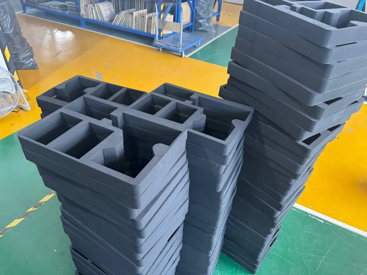
Bolts need something to push against. Torque 1.5 N·m into a 3.0 mm wall and the panel sinks 0.3 mm, slackening the gasket the torque was meant to load. A 4 mm nylon backing plate, or a flange clamped from both sides, spreads that load over the whole ring.
Pitch follows the circumference. A 46 mm flange measures 145 mm around, so six bolts sit 24 mm apart; four bolts stretch the pitch to 36 mm and let the pad bulge 0.15 mm between fixings, which is where water enters.
| Bore | Flange OD | Bolts | Torque | Backing plate |
|---|---|---|---|---|
| 12 mm | 38 mm | 4 × M3 | 0.6–0.8 N·m | 3 mm |
| 16 mm | 42 mm | 4 × M4 | 1.0–1.2 N·m | 3 mm |
| 20 mm | 46 mm | 6 × M4 | 1.2–1.5 N·m | 4 mm |
| 25 mm | 52 mm | 6 × M4 | 1.5–1.8 N·m | 4 mm |
| 32 mm | 60 mm | 8 × M5 | 2.0–2.5 N·m | 5 mm |
3. How grooves and rings hold the bore
The flange supplies the face; the groove gives the ring a home. Cut it at 1.25 times the cord width and 0.75 times deep and compression lands near 25 %: a 3.0 mm cord in a 3.8 mm groove, 2.2 mm deep, squashes 0.8 mm.
Hold the groove floor to 0.1 mm, because that is compression budget rather than fussiness. A floor bowing 0.2 mm lets the ring under-compress in one arc, dropping from 25 % to 18 %.
| Cord | Groove width | Groove depth | Compression | Bore range |
|---|---|---|---|---|
| 2.0 mm | 2.5 mm | 1.5 mm | 25 % | 8–12 mm |
| 2.5 mm | 3.1 mm | 1.9 mm | 24 % | 12–18 mm |
| 3.0 mm | 3.8 mm | 2.2 mm | 27 % | 16–25 mm |
| 3.5 mm | 4.4 mm | 2.6 mm | 26 % | 22–32 mm |
| 4.0 mm | 5.0 mm | 3.0 mm | 25 % | 28–40 mm |
The bore edge needs work too. A step drill leaving a 0.5 mm × 45° chamfer and a wall finished under Ra 1.6 μm closes the path; 6.3 μm tool marks let water walk the helix.
Never mill the groove into a 3.0 mm wall. A 2.2 mm groove plus 0.9 mm of floor leaves 3.1 mm of panel, and that floor cracks before the bolt reaches torque.
4. When potting or rubber pads replace a flange
Where the cable never moves again, potting beats a flange. Two-part polyurethane at 1:1, poured 8 mm deep, cures 24 hours at room temperature to 60 Shore A with 1.5 N/mm of adhesion.
Back the bore with 10 mm of closed-cell foam before pouring, or resin runs inside. The trade is permanence: peeling 1.5 N/mm of resin takes about 20 minutes a hole, and the bore widens 0.5–1.0 mm.
| Method | Reopenable | Cost per hole | Bore range | Best for |
|---|---|---|---|---|
| Flange clamp | Repeatedly | 18–35 CNY | 8–60 mm | Cables under service |
| Groove and ring | Yes, spare ring | 12–28 CNY | 8–40 mm | Small bores, frequent checks |
| Potting | No | 6–15 CNY | 5–30 mm | Sealed once, no service |
| Butyl pad | About three times | 8–20 CNY | 10–35 mm | Rare maintenance |
A butyl pad sits between the two: 3 mm of butyl under a 2 mm plate survives about three reopenings, and returns 92 % of its thickness after 20 cycles from -30 °C to 90 °C.
5. Placement clearances and holding the rating
Placement decides more than the part does. Keep the bore centre 25 mm from a corner, 20 mm from the rim seal line and 30 mm from a latch seat, because all three guard wall thickness that changes.
Panels run 0.8 mm thinner between ribs than at the root, so a bore in the middle sags 0.4 mm under clamp load and the sealing line opens.
Whatever rating the case carried does not survive the drill. After a cutout the local rating belongs to the new sealing line alone, and one failed port sets the number for the whole case.
Space ports apart. Centres closer than 30 mm overlap the clamp rings, and the 10 mm strip between them lifts first. Pressure needs a way out too: a 40 °C swing can push 8 kPa and pin the ring, so add a 2 mm vent.
Conclusion
Case cutout sealing is settled by four checks in order. Measure the wall first: under 4.5 mm, skip grooves and use a flange with a backing plate. Measure placement second: within 25 mm of a corner, move the bore rather than upgrade the part. Ask third whether the cable will ever be reopened, since a yes means a flange. Choose the part last, sizing the flange at bore plus twice an 8 mm ring. The hole is only an opening; the 8 mm ring of clamp face and the bolts loading it keep water out.
This article discusses container-side specifications and design implications only, and does not cover any handling, loading or use of the contents.
Related Reading
- How the gasket groove section is set
- What a pressure relief valve does on a case
- Judging when a gasket needs replacing
- Specifying a custom plastic protective case
- How case interior dimensions are measured
Related Products
- 8 Series — Gun Cases; Military Equipment Cases; Camera Equipment Cases; Drone Cases; Watch Cases; Knife Cases; First Aid Cases; Electronics Equipment Cases
- WL8-2812 PP Gun Case — model WL8-2812
- All protective cases and toolboxes: 7 series, 158 models